siat SR4-S Type A Guide
Publication code: SMB00051K.2
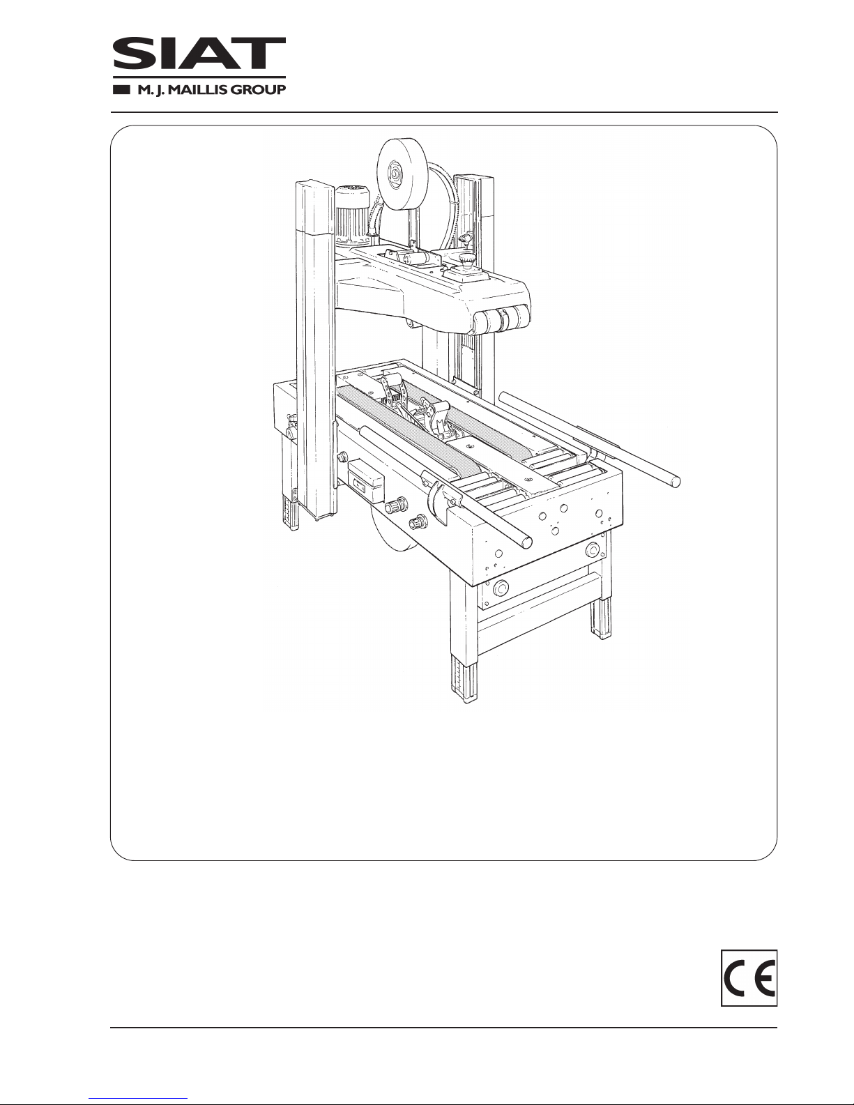
SR4-S Type A
NASTRATRICE AUTOMATICA
AUTOMATIC CASE SEALING MACHINE
MACHINE ENRUBANNEUSE AUTOMATIQUE
AUTOMATISCHE KARTONVERSCHLIESSMASCHINE
PRECINTADORA AUTOMATICA
MANUALE DI ISTRUZIONI E PARTI DI RICAMBIO
INSTRUCTIONS MANUAL AND SPARE PARTS LIST
MANUAL D’INSTRUCTIONS ET PIECES DETACHEES
BEDIENUNGSANLEITUNG UND ERSTAZTEILLISTE
MANUAL DE INSTRUCCIONES Y RECAMBIOS
SIAT
S.p.A. - Via Puecher, 22 - 22078 TURATE (CO) ITALY - P.O. BOX 1
Tel. 02-964951 - Telefax 02-9689727
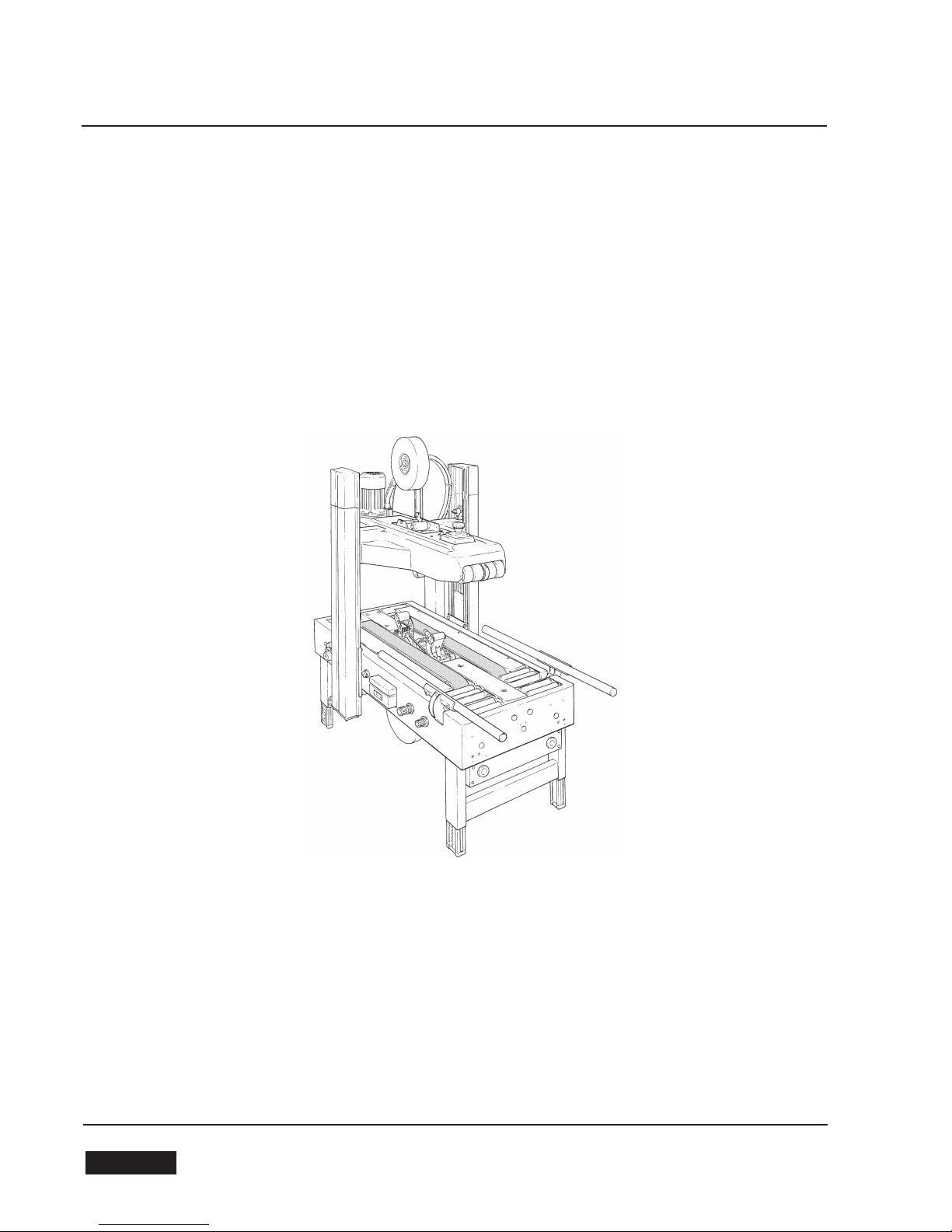
SR4-S Type A
AUTOMATIC ADJUSTMENT CASE SEALING MACHINE WITH TOP AND BOT-
TOM DRIVE BELTS
-Maximum box size h. 500 mm x w. 500 mm
-Adhesive tape 50 mm
-Belt speed 22 m per minute
-Production 800 boxes per hour (average)
Instruction manual for the use, safety, maintenance and spare parts concerning the case sealing machine model SR4-
S Type A.
This publication is property of SIAT S.P.A.
Via Puecher, 22 - 22078 TURATE (CO) - ITALY
Tel. 02-964951 - Fax. 02-9689727
Edition September 2013
The reproduction of this manual is strictly forbidden. All rights reserved © Siat S.p.A. 2013.
The manufacturer reserves the right to modify the product at any time without notice.
Publication n. SMB00051K.2
Release
54 February 2007
ENGLISH

INDEX ABBREVIATIONS AND ACRONYMS
Section
Manufacturing specifications 1.1
Manual, how to use the 1.2
Serial Number 2.1
After-sale service 2.2
Warranty 2.3
Safety 3
Operators' skill levels 3.6
Technical specifications 4
Dimensions and weight 4.2.-4.6
Noise measurement 4.10
Transportation 5
Unpacking 6
Installation 7
Theory of operation 8
Controls 9
Safety devices 10
Set-up and adjustments 11
Tape replacement 11.1-11.2
Operation 12
Cleaning 12.5
Trouble shooting 12.8
Maintenance 13
Lubrication 13.5
Blade replacement 13.9
Belt replacement 13.10-13.11
Adjustment of belt tension 13.12
Log of maintenance work 13.13
Fire emergency 14.2
Enclosures 15
Electric Schematics 16
Pneumatic Schematic 16
Spare parts last section
LIST OF ABBREVIATIONS, ACRONYMS AND UNUSUAL
TERMS TO BE FOUND IN THIS MANUAL
Dwg. = drawing
Encl. = enclosure
Ex. = example
Fig. = figure showing spare parts
Max. = maximum
Min. = minimum
Mod. = machine model
N. = number
N/A = not applicable
OFF = machine stopped
ON = machine running
OPP =
oriented polypropylene adhesive tape
Pict. = picture
PLC = Programmable Logic Control
PP = polypropylene
PTFE = Polytetrafluorethylene
PVC = Polyvinylchloride
Ref. = reference mark
SIAT SPA = Società Internazionale Applicazioni
Tecniche (Società per Azioni)
Tav. = Illustration
w = width
h = height
l = length
ol = overall length
cbh = conveyor bed height
55
February 2007 ENGLISH

INTRODUCTION
1.1 MANUFACTURING SPECIFICATIONS
The automatic case sealing machine Mod. SR4-S has been designed and manufactured compling with the
legal requirements in force at the date of its manufacture.
THE REFERENCE DOCUMENTS ARE:
1.2 HOW TO READ AND USE THE INSTRUCTION MANUAL
1.2.1 IMPORTANCE OF THE MANUAL
The manual is an important part of the machine; all information contained herein is intended to enable the
equipment to be maintained in perfect condition and operated safely. Ensure that the manual is available to all
operators of this equipment and is kept up to date with all subsequent amendments. Should the equipment be
sold or disposed of, please ensure that the manual is passed on. Electrical and pneumatic diagrams are inclu-
ded in the manual. Equipment using PLC controls and/or electronic components will include relevant schematics
or programmes in the enclosure, and in addition the relevant documentation will be delivered separately.
1.2.2 MANUAL MAINTENANCE
Keep the manual in a clean and dry place near the machine. Do not remove, tear or rewrite parts of the manual
for any reason.
Use the manual without damaging it.
In case the manual has been lost or damaged, ask your after sale service for a new copy, quoting the code num-
ber of the document.
1.2.3 CONSULTING THE MANUAL
The manual is composed of:
- pages which identify the document and the machine;
- index of the subjects:
- instructions and notes on the machine: sections 2÷14
- enclosures, drawings and diagrams:
sections 15÷16
- spare parts: last section.
All pages and diagrams are numbered. The spare parts lists are identified by the figure identification number.
All the notes on safety measures or possible dangers are identified by the symbol:
All the important warning notes related to the operation of the machine are identified by the symbol:
The parts typed in bold refer to technical data or technical notes on a specific subject.
1.2.4 HOW TO UPDATE THE MANUALIN CASE OF MODIFICATIONS TO THE MACHINE
Modifications to the machine are subject to manufacturer’s internal procedures.
The user receives a complete and up-to-date copy of the manual together with the machine.
Afterwards the user may receive pages or parts of the manual which contain amendments or improvements
made after its first publication.
The user must use them update this manual.
65
ENGLISH Dic. 2011
Machines guidelines 2006/42/CE
Standards applied
UNI EN 415-7
EN 415-9:2009
Guidelines EMC 2004/108/CE
Standards applied
CEI EN 60204-1:2006
EN 61000-6-2:2005
EN 61000-6-4:2007
2-GENERAL INFORMATION
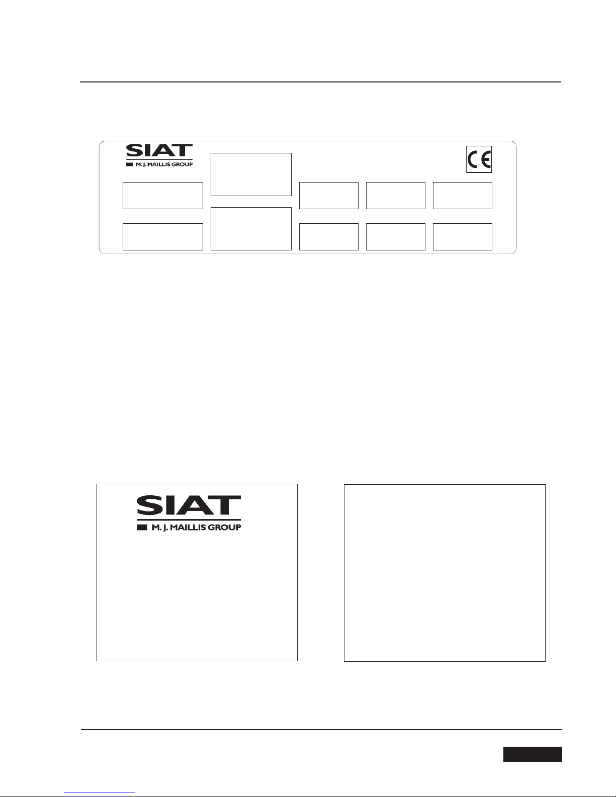
2.1 SERIAL NUMBER OF THE MACHINE AND NAME OF THE MANUFACTURER
2.2 FOR AFTER-SALE SERVICE AND SPARE PARTS PLEASE APPLY TO:
SIATs.p.a.Via G.Puecher N°22
Turate (CO) ITALY
Model
Part Number
Type
Serial Number
Ampere Watt
Year
Volt Hertz Phase
Via Puecher, 22
22078 TURATE (CO) - ITALY
Tel. 02-964951
Fax. 02-9682239
E-mail [email protected]
AGENT/DISTRIBUTOR OR LOCAL
AFTER SALE SERVICE:
57
February 2007 ENGLISH

SIAT S.p.A.
Via Puecher, 22 - 22078 TURATE (CO) ITALY - Tel. 02964951 - Fax 029689727 - http://www.siat.com - Email: [email protected]
WARRANTY
Within the limits of what is set forth below, Seller agrees to repair or replace without cost to Buyer any defective goods when such de-
fect occurs within a period of twelve (12) months from the date in which Seller's goods have been put into use, but in no event beyond
thirteen (13) months from the date of shipment.
Expressly excluded from this warranty are those parts subject to normal wear and tear (by way of illustration, but not limitation, such
parts as belts, rubber rollers, gaskets, brushes, etc.) and electrical parts.
Buyer must immediately notify Seller of any defect, specifying the serial number of the machine.
Buyer shall send to Seller the defective item for repair or replacement. Seller will perform the repairs or provide a replacement within a
reasonable period of time.
Upon effecting such repair or replacement, Seller shall have fulfilled its warranty obligations. In the event the repairs or replacement
must be effected at the place where the machine is installed, all expenses for labor, travel and lodging of Seller's personnel shall be
sustained by the Buyer. Buyer will be invoiced in conformity with Seller's standard charges for the services rendered.
Seller is not responsible for defects resulting from:
- Improper use of the machine
-Lack of proper maintenance
- Tampering with the machine or repairs effected by the Buyer.
Seller will not be liable for any injury to persons or things or for the failure of production. With respect to the materials not manufactu-
red by Seller, such as motors and electrical equipment, Seller will grant to Buyer the same warranty Seller receives from its supplier of
such materials.Seller does not warrant the compliance of its machines with the laws of non-EEC countries in which the machines may
be installed, nor does it warrant compliance with laws or standards relating tothe prevention of accidents or pollution.
Adaptation of Seller's machines to the aforesaid laws or standards shall be the responsibility of Buyer who assumes all liability there-
fore.
Buyer shall indemnify and hold Seller harmless against any claim by third parties resulting from failure to comply with the aforesaid laws
and standards.
3-SAFETY
3.1 GENERAL SAFETY INFORMATION
Read all the instructions carefully before starting the work with the machine; please pay particular attention to
sections marked by the symbol
Keep this manual in a handy place near the machine: its information will help you to maintain the machine in
good and safe working condition.
3.2 DEFINITION OF THE OPERATORS' QUALIFICATIONS
- Machine operator
- Maintenance technician
- Electrician
- Manufacturer’s technician
Only persons who have the skills described in the following page should be allowed to work on the machine.
It is the responsibility of the user to appoint the operators having the appropriate skill level and the appropriate
training for each category of job.
The machine is provided with a LOCKABLE EMERGENCY STOP BUTTON placed
on the upper head of the machine; when this button is pressed, it stops the ma-
chine at any point in the working cycle without cutting the pneumatic circuit.
Disconnect the machine from the mains before any maintenance operation.
SKILL 1
MACHINE OPERATOR
This operator is trained to use the machine with the machine controls, to feed cases into the machine, make
adjustments for different case sizes, to change the tape and to start, stop and restart production.
N.B.: the factory manager must ensure that the operator has been properly trained on all the machine functions
before starting work.
59
February 2007 ENGLISH

3-SAFETY
SKILL 2
MECHANICAL MAINTENANCE TECHNICIAN
This operator is trained to use the machine as the MACHINE OPERATOR and in addition is able to work with
the safety protection disconnected, to check and adjust mechanical parts, to carry out maintenance operations
and repair the machine.
He is not allowed to work on live electrical components.
SKILL 2a
ELECTRICAL MAINTENANCE TECHNICIAN
This operator is trained to use the machine as the MACHINE OPERATOR and in addition is able to work with
the safety protection disconnected, to make adjustments, to carry out maintenance operations and repair the
electrical components of the machine.
He is allowed to work on live electrical panels, connector blocks, control equipment etc.
SKILL 3
SPECIALIST FROM THE MANUFACTURER
Skilled operator sent by the manufacturer or its agent to perform complex repairs or modifications, when agreed
with the customer.
3.3 INSTRUCTIONS FOR A SAFE USE OF THE MACHINE
Only persons who have the skills described on the following paragraph 3.6 are allowed to work on the ma-
chine.
It is responsibility of the user to appoint the operators having the appropriate skill level and the appropriate
training for each category of job.
3.4 STATE OF THE MACHINE
List of the modes which are possible with this machine:
- automatic running;
- running with safety protections removed or disabled;
- stopped by using the main switch;
- stopped by using the lockable emergency stop button;
- electric power disconnected;
- compressed air disconnected.
60 February 2007
ENGLISH

3-SAFETY
3.5 NUMBER OF THE OPERATORS
The operations described hereinafter have been analized by the manufacturer; the number of operators
shown for each operation is suitable to perform it in the best way.
A smaller or larger number of operators could be unsafe.
3.6 OPERATORS’ SKILL LEVELS
The table below shows the minimum operator's skill for each operation with the machine.
OPERATION
Installation and set up of the ma-
chine.
Adjustment of the box size.
Tape replacement.
Replacement of blades.
Replacement of drive belts.
Ordinary maintenance
(mechanical).
Ordinary maintenance (electrical).
Extraordinary maintenance (me-
chanical).
Extraordinary maintenance
(electrical).
STATE OF THE MACHINE
Running with safety protections disabled.
Stopped by pressing the EMERGENCY
STOP button.
Stopped by pressing the EMERGENCY
STOP button.
Electric power disconnected.
Electric and pneumatic power disconnec-
ted.
Electric and pneumatic power disconnec-
ted.
Electric and pneumatic power disconnec-
ted.
Running with safety protections disabled.
Running with safety protections disabled.
OPERATOR'S
SKILL
2 and 2a
1
1
2
2
2
2a
3
3
NUMBER OF
OPERATORS
2
1
1
1
1
1
1
1
1
61
February 2007 ENGLISH
3-SAFETY
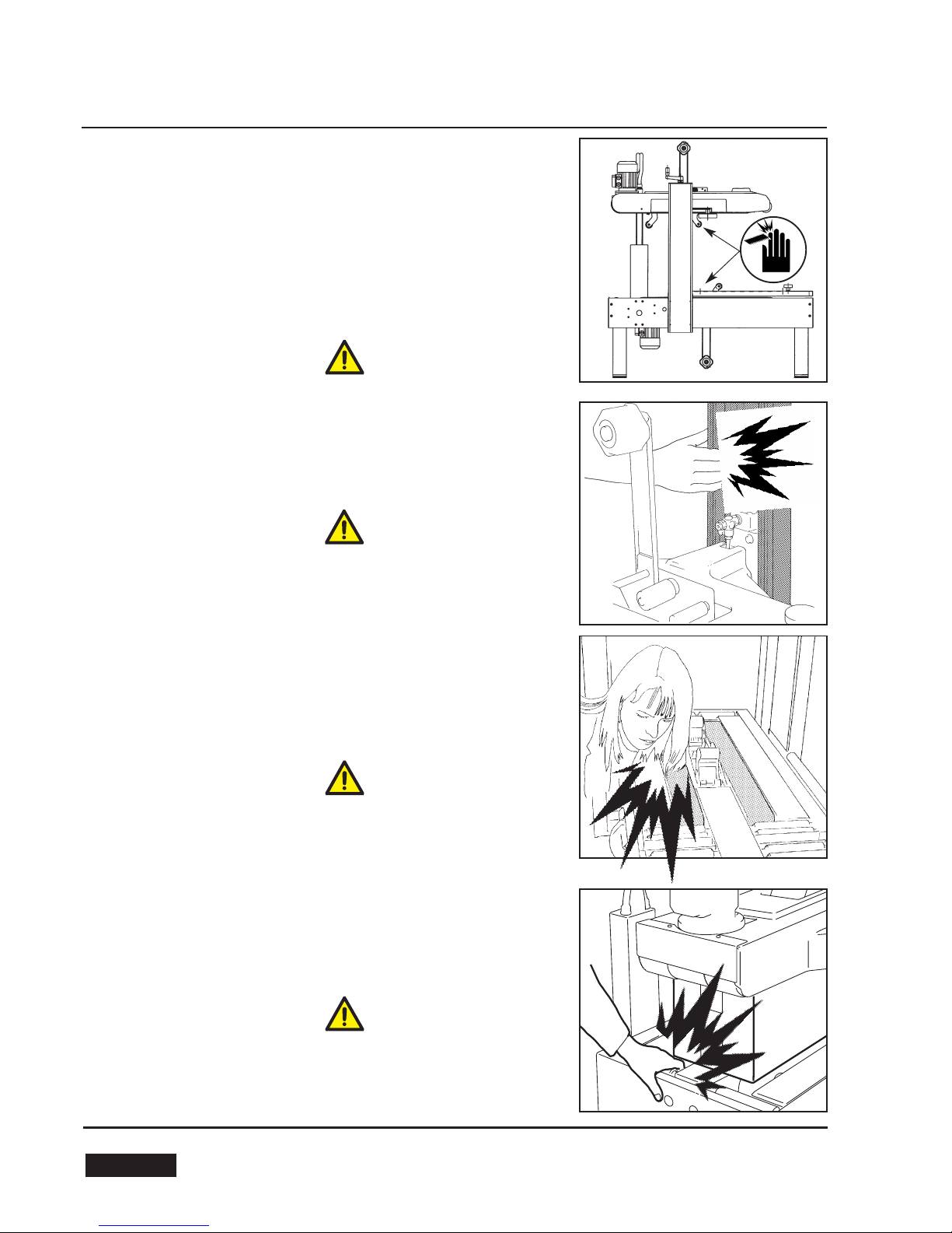
3.7 RESIDUAL HAZARDS
The case sealer SR4-S has been designed following the CE 392 direc-
tives, and incorporates various safety protections which should never
be removed or disabled.
Notwithstanding the safety precautions conceived by the designers of
the machine, it is essential that the operator and service personnel be
warned that the following uneliminable residual hazards exis
WARNING! Tape cutting blades.
Never remove the safety device which covers the blade on the top and
bottom taping units.
Blades are extremely sharp. Any error may cause serious injuries.
WARNING! Pneumatic drives of the upper head housed inside the co-
lumns.
Keep hands away.
WARNING! Upper and lower drive belts.
Never work on the machine with loose hair or loose garments such as
scarfs, ties or sleeves.
Although protected, the drive belts may be dangerous.
WARNING! Cavity in the conveyor bed.
Never put your hands inside any part of the machine while it is working.
Serious injury may occur.
62 February 2007
ENGLISH
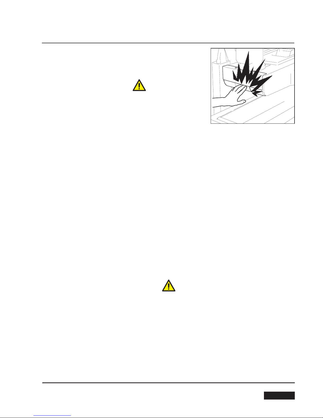
3-SAFETY
WARNING! Top driving belts.
Never touch the running belt with your hands.
Serious injury may occur.
3.8 RECOMMENDATIONS AND MEASURES TO PREVENT OTHER HAZARDS WHICH CANNOT BE ELIMI-
NATED
The operator must stay on the working position shown on paragraph 12.1. He must never touch the running dri-
ving belts or put his hands inside any cavity.
The box must be fed by keeping the hands in the right position. (see paragraph 4.9)
The operator must pay attention to the blades during the tape replacement.
3.9 PERSONAL SAFETY MEASURES
(Safety glasses, safety gloves, safety helmet, safety shoes, air filters, ear muffs).
None is required, except when recommended by the user.
3.10 PREDICTABLE ACTIONS WHICH ARE
INCORRECT AND NOT ALLOWED
- Never try to stop or hold the box while it is being driven by the belts.
Use only the EMERGENCY STOP BUTTON.
- Never work without the safety protections.
-
Never remove or disable the safety devices.
- Only authorised personnel should be allowed to carry out the adjustments, repairs or maintenance which re
quire operation with reduced safety protections. During such operations, access to the machine must be re
stricted. When the work is finished, the safety protections must immediately be reactivated.
- The cleaning and maintenance operations must be performed after disconnecting the electric power.
- Clean the machine using only dry clothes or light detergents. Do not use solvents, petrols etc.
- Do not modify the machine or any part of it. The manufacturer will not be responsible for any modifications.
- We advise to apply directly to Siat for modifications.
- Follow carefully the installation instructions of this manual. The manufacturer will notbe responsible for dama
ges caused by improper installation.
63
February 2007 ENGLISH
3-SAFETY
Label code: 3.0.010604.96/A
Label code: 3.0.01029.96A
Label code: 3.0.01047.96A
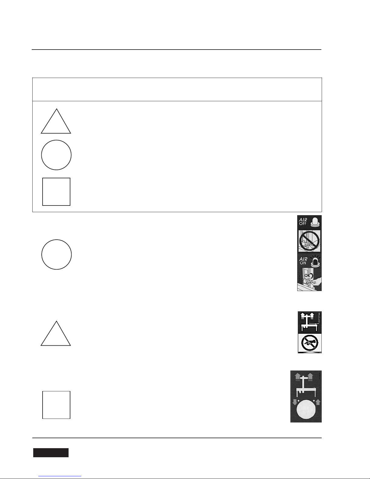
SYMBOLS COLOURS
DANGER AND PARTS IN MOVEMENT
COMPULSORY ACTIONS/PROHIBITION
CONTROLS AND INFORMATION
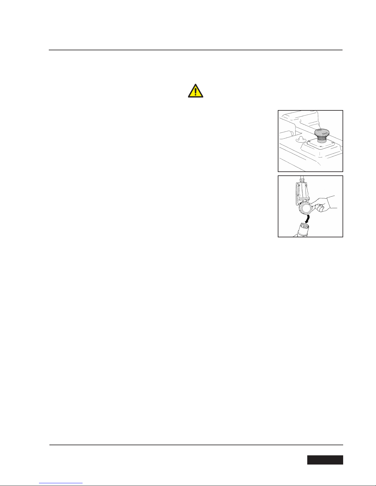
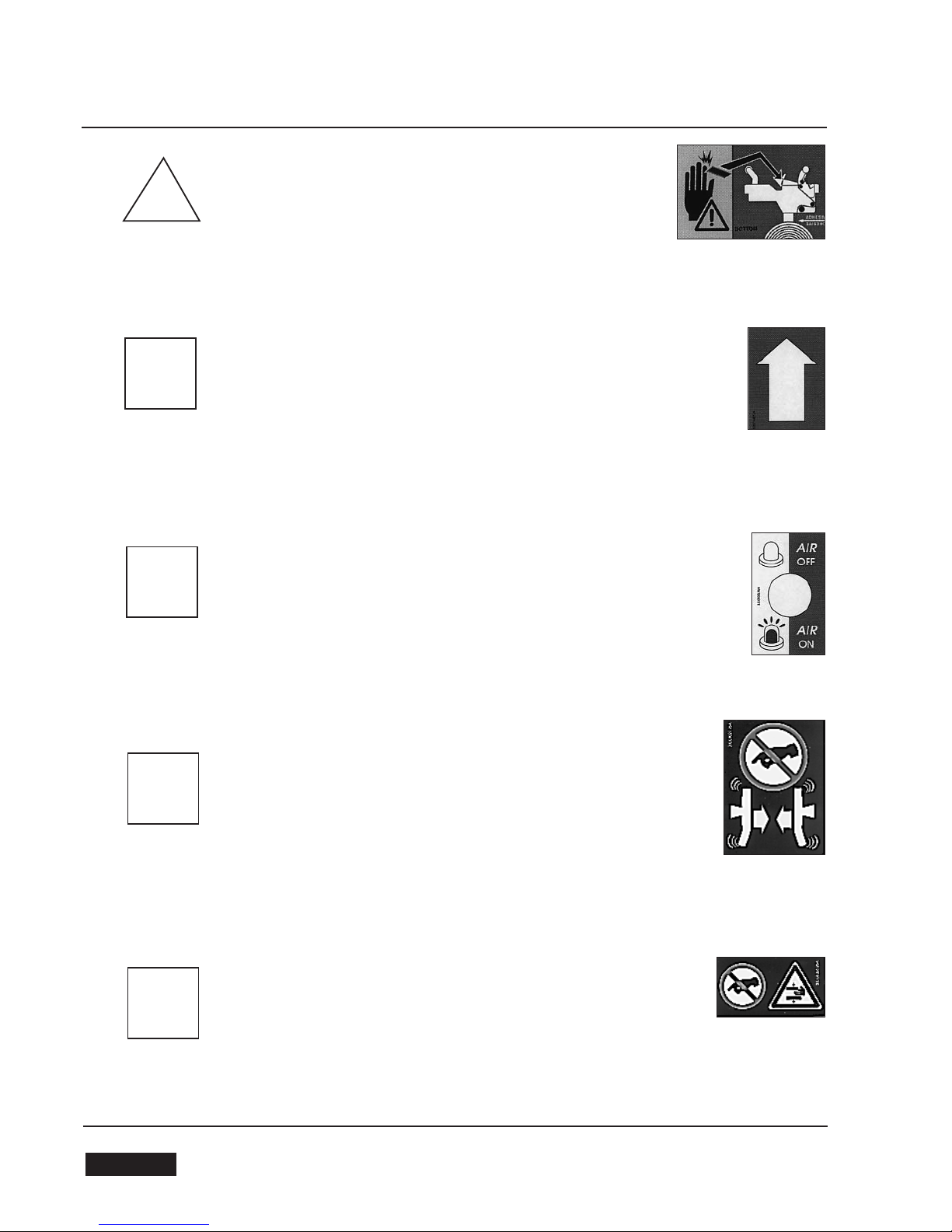
Warns the operator that the adjustable upper head
cylinder stop must not be released if compressed air
is OFF.
Warns the operator not to touch the lever that actua-
tes the valve for the upper head ascent.
Show the selector to raise/lower the upper head as-
sembly to make easily accessible the bottom taping
unit for tape replacement.
YELLOW COLOUR
RED COLOUR
LIGHT BLUE COLOUR
a
b
c
3.11 TABLE OF WARNINGS, LABELS, PLATES AND DRAWINGS TO BE FOUND ON THE MACHINE
64 February 2007
ENGLISH
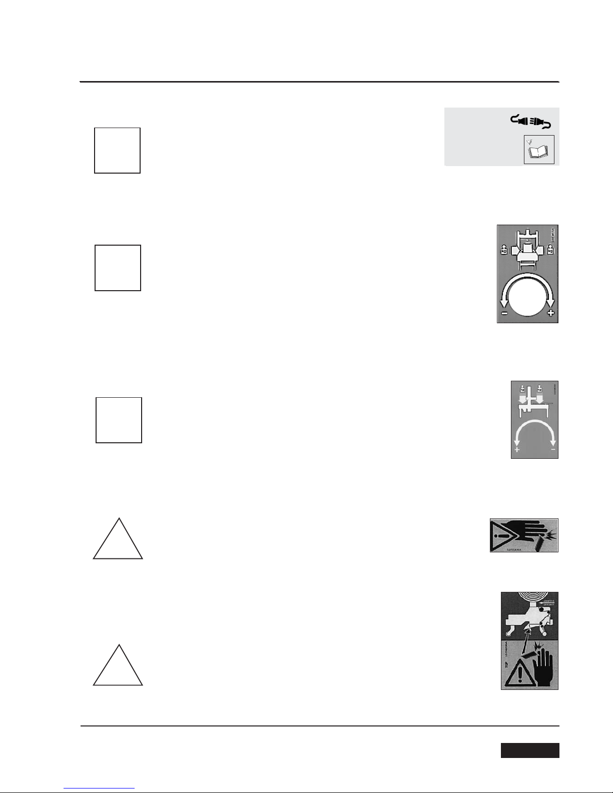
Before starting any maintenance operations the electrical
power must be disconnected.
Show the knob to adjust the pressure of the side guides
againts the box.
Show the knob to adjust the weight of the upper head assem-
bly on the box.
Show the sharp knife on the taping head.
Tape threading path for top taping unit, and position of the sharp
knife.
3-SAFETY
Label code: 3.0.01050.96A
Label code: 3.0.01049.96A
Label code: 3.0.01048.96A
Label code: 3.0.01028.96A
Label code: 3.0.01023.96A
d
e
f
g
h
CAUTION: DISCONNECT
PLUG BEFORE SERVICING
ATTENTION: DETACHER
LA FICHE AVANT L’ENTRETIEN
ATENCIÓN: DESCONECTE EL ENCHUFE
DE ALIMENTACIÓN ANTES LA MANUTEN-
CIÓN
ACHTUNG: VOR DER WARTUNG, DEN-
STECKER ABSCHALTEN
ATTENZIONE: STACCARE LA SPINA PRIMA
DELLA MANUTENZIONE
3.0.01050.96A
65
February 2007 ENGLISH
3-SAFETY
Tape threading path for bottom taping unit and position of
the sharp knife.
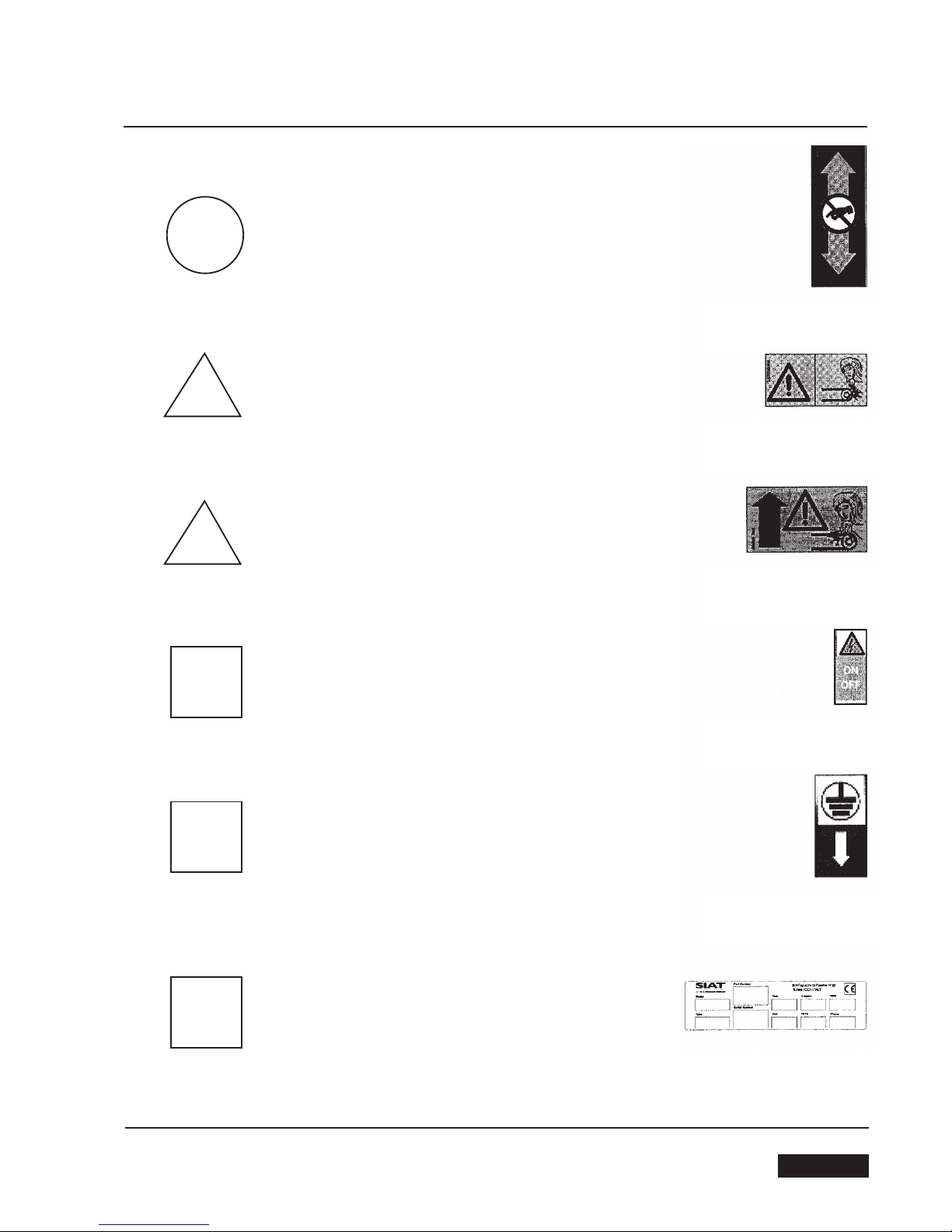
Show the running direction of the belts.
Show that airs is in the circuit (red indicator is up).
Warns the operator not to touch the lever that actuates the
closing/opening of the box side guides.
Warns the operator not to introduce the hands into the ca
vities of the box side guides.
LAbel code: 3.0.01024.96A
Label code: 3.0.01040.96A
Label code: 3.0.01035.96A
Label code: 3.0.01027.96A
Label code: 3.0.01036.96A
i
l
m
n
o
66 February 2007
ENGLISH
3-SAFETY
Warns the operator to keep hands away from the pneumatic
cylinder housed inside the columns.
Shows the danger of the upper drive belts when run
ning.
Show the danger of the bottom drive belts when running.
Show the start/stop control and that inside thwe circuit brea
ker box there is electric currenty.
Show the point for eartjh wire connection on the machine
frame.
Identification data for the machine model, serial number and
manufacturer.
LAbel code: 3.0.01041.96A
Label code: 3.0.01030.96A
Label code: 3.0.01031.96A
Label code: 3.0.01090.96A
Label code: 3.0.01039.96A
Label code: SBC0000629
p
q
r
s
t
u
67
February 2007 ENGLISH
2 OUTER COLUMN IN HIGH POSITION
1 OUTER COLUMNS IN LOW POSITION
4-PRELIMINARY INFORMATION ON THE MACHINE
4.1
GENERAL DESCRIPTION OF THE MACHINE
Automatic case sealer with top and bottom drive belts and automatic adjustment to the box size to be sealed.
4.2
TECHNICAL SPECIFICATIONS
- Production = 800 boxes/hour (average)
- Standard power supply = 230/400 V 50Hz 3Ph
- N.2 motors (HP 0,18) KW 0,12
- Taping units K11, tape width 50 mm.
- Weight = 155 kg.
- Belts speed = 22 m per minute
- Compressed air = 6 Bar max.
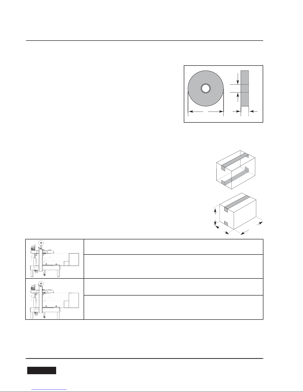
4.3 TAPE DIMENSIONS
Suitable adhesive tapes:
PVC
OPP
ADHESIVE PAPER
AB
C
4.4 PURPOSE OF THE MACHINE
The machine is designed to seal with adhesive tape cases having the dimensions (in millime-
ters) shown in section 4.5, by applying two tape stripes on their top and bottom flaps simul-
taneously.
4.5 BOX-SIZE RANGE
The case sealer SR4-S is automatically adjustable to any box sizes included in the range
shown below (part 1).
To seal boxes higher than 500 mm, it is possible to modify the position of the outer columns
as shown in the drawing below (part 2).
h
wl
A= 410 mm max
B= 50 mm
C= 76 mm
NOTES
lThe box length (L) refers to the size in the seal direction.
lThe boxes should have a H/L ratio (HEIGHT/LENGTH) of 0,5 or higher.
Boxes with a lower ratio should be test run to ensure perfect performance, which depends upon various factors such as box weight
and rigidity.
lSome special modifications are available from the manufacturer in order to seal box formats smaller or larger than the standard sizes
described herein. If interested, please contact your Siat Service Dealer
BOX SIZE MIN MAX
L150
W140 500
H110 500
BOZ SIZE MIN MAX
L150
W140 500
H135 550
68 February 2007
ENGLISH

4.6 DIMENSIONS
MACHINE OVERALL DIMENSIONS
l = length 1240 mm
w= width 740 mm
h = height
1275÷2025
mm
ol =
overall length including centering bars: 1390 mm
cbh
= conveyor bed height: section 4.7
h
wl
ol
cbh
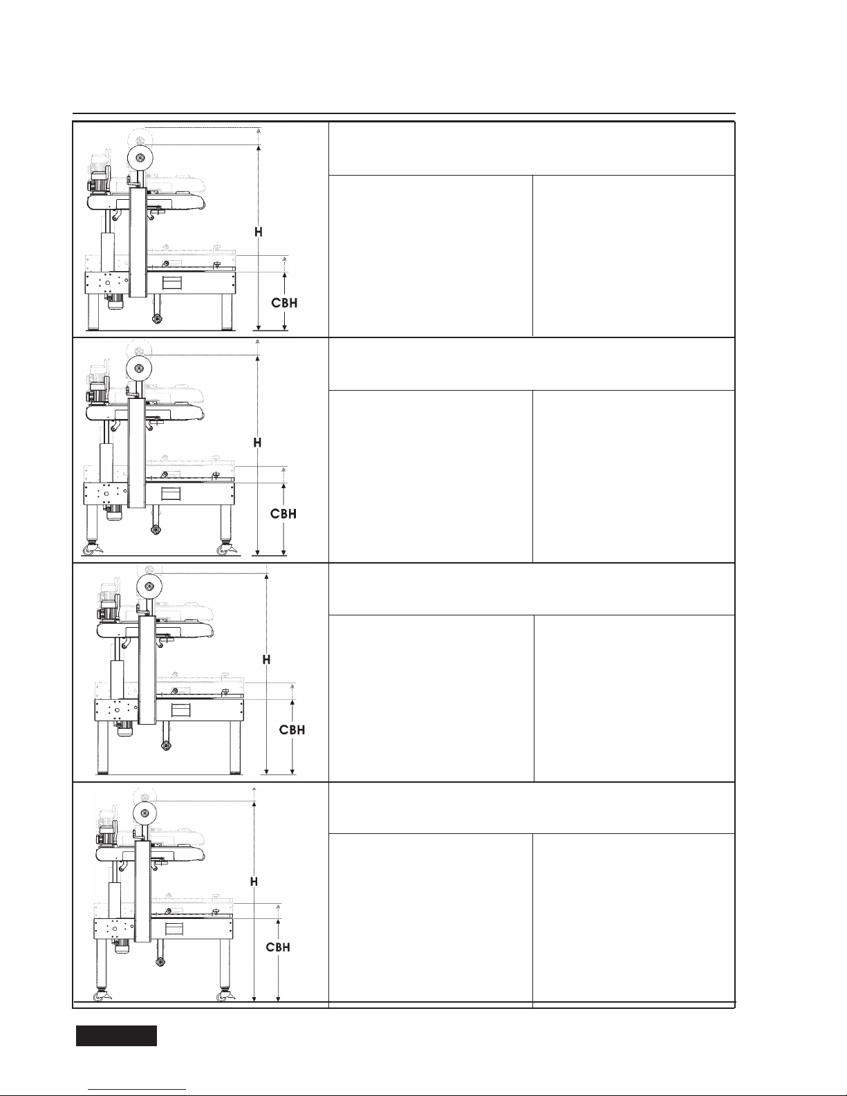
4.7 CONVEYOR BED HEIGHT
The case sealer SR4-S allows for a wide range of conveyor bed height. Various combinations are possible
with the use of the optional accessories AS77 (casters) and AS80 (legs), as shown in the following page.
4-PRELIMINARY INFORMATION ON THE MACHINE
69
February 2007 ENGLISH
4-PRELIMINARY INFORMATION ON THE MACHINE
AWITH STANDARD LEGS
BWITH AS77 CASTERS (OPTIONAL)
CONVEYOR BED HEIGHT
MIN MAX
CBH 485 825
OVERALL DIMENSIONS
MIN MAX
H1275 2025
L1390 1390
W740 740
CONVEYOR BED HEIGHT
MIN MAX
CBH 585 925
OVERALL DIMENSIONS
MIN MAX
H1375 2125
L1390 1390
W740 740
CWITH AS80 LEGS (OPTIONAL)
CONVEYOR BED HEIGHT
MIN MAX
CBH 645 1135
OVERALL DIMENSIONS
MIN MAX
H1435 2335
L1390 1390
W740 740
CONVEYOR BED HEIGHT
MIN MAX
CBH 745 1235
OVERAL DIMENSIONS
MIN MAX
H1535 2435
L1390 1390
W740 740
DWITH AS80 LEGS AND AS77 CASTERS (OPTIONAL)
70 February 2007
ENGLISH
4-PRELIMINARY INFORMATION ON THE MACHINE
4.8 MAIN COMPONENTS
The machine is composed of:
N. 1 frame
N. 4 adjustable legs
N. 2 columns
N. 2 taping units
N. 1 top head support
N. 1 top drive belts assembly
N. 1 bottom drive belts assembly
N. 2 electric motors
N. 1 emergency stop button
N. 1 main switch ON/OFF
For the technical features of the electric parts refer to section 15-ENCLOSURES
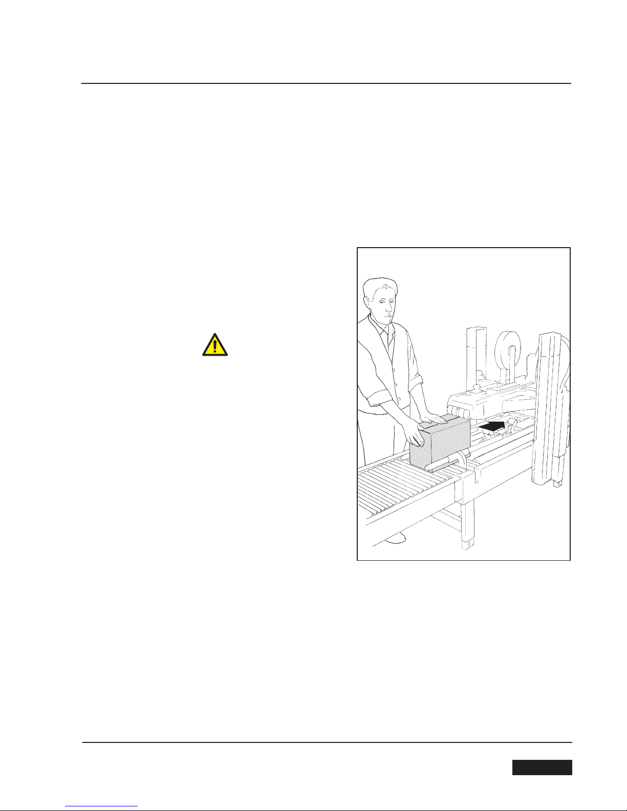
4.9 OPERATIVE FLOW
Once the box has been filled, close its top flaps and
push it against the lever that controls the ascent of the
upper head. Insert the box into the machine until it
overhangs the drive belts that will drag it through the
taping heads.
Keep hands always as shown on Picture.
The box will be automatically sealed with adhesive tape
on the top and bottom box seams. Then it will be expel-
led on the exit conveyor.
4.10 MACHINE NOISE MEASUREMENT
Acoustic pressure at 1 meter distance from the machine with the tape roll inserted: 73 dB. Acoustic pressure
at a height of 1,6 meter above the
machine
with the tape roll inserted: 73 dB.
The measurement has been performed by a SPYRI-MICROPHON phonometer.
71
February 2007 ENGLISH
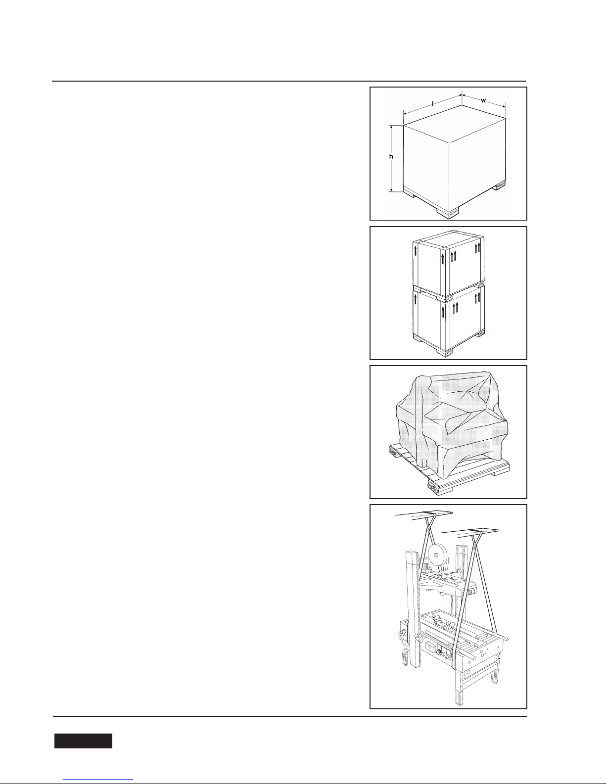
5-SHIPPING-HANDLING-PACKAGE
5.1 SHIPMENT AND HANDLING OF THE PACKED MACHINE
The machine is fixed on the pallet with four bolts and can be uplifted
by using a forktruck.
The packaging is suitable to travel by land and by air. Optional sea-
freight packaging available.
PACKAGING OVERALL DIMENSIONS
l = length 1300 mm
w= width 800 mm
h= height 1100 mm
Weight kg. 180
During the shipment it is possible to stack a maximum of 2 machines.
5.2
PACKAGING FOR OVERSEAS SHIPMENT
(OPTIONAL)
The machines shipped by sea freight are covered by an aluminum/po-
lyester/ polythene bag which contains dehydrating salts.
5.3 SHIPMENT AND HANDLING OF THE UNPACKED MACHINE
The unpacked machine can only be moved short distances and indo-
ors only.
The transportation of the machine without packaging may cause damage
and accidents. In case it is necessary to relocate the machine, lift it with
belts as shown in Picture.
MACHINE OVERALL DIMENSIONS
length 1390 mm.
width 740 mm.
height
min.1275; max. 2025 mm.
Weight kg 155,5
5.4 STORAGE OF THE PACKED OR UNPACKED MACHINE
If the machine is left inactive for a long period, please take the following pre-
cautions:
-store the machine in a dry and clean place;
-if the machine is unpacked it is necessary to protect it from the dust
and do not stack anything over the machine;
-it is possible to stack a maximum of 2 machines, if they are in their
original packing.
72 February 2007
ENGLISH
Table of contents
Other siat Kitchen Appliance manuals


