Elektral ThruScan Series User manual


1
Contents Page
PREFACE ........................................................................................................................ 4
Contents......................................................................................................................... 5
Before Use ..................................................................................................................... 6
1. GENERAL DESCRIPTION ............................................................................................ 8
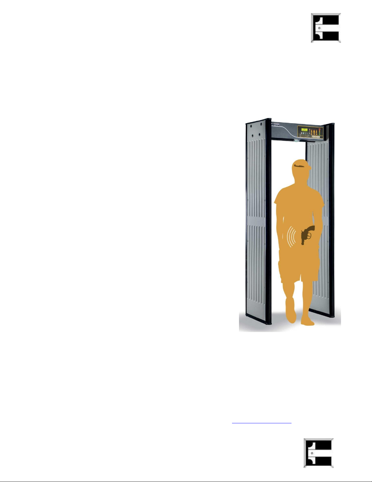
1.1 ThruScan s3 Walk Through Metal Detector ........................................................... 9
1.3 ThruScan s6 Walk Through Metal Detector .........................................................10
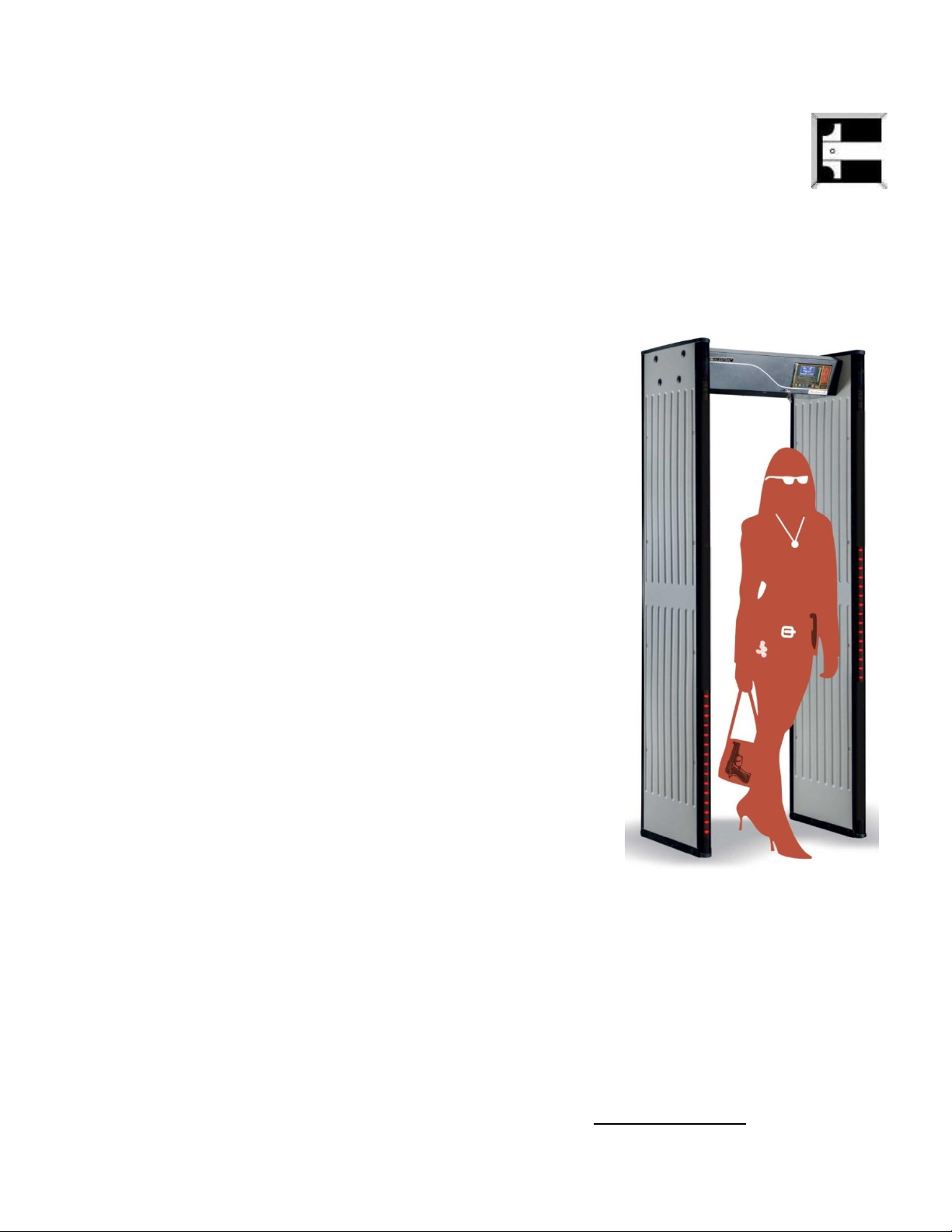
1.3 ThruScan s9 Walk Through Metal Detector .........................................................11
1.4 ThruScan sX Walk Through Metal Detector .........................................................12
1.5 ThruScan sX-WP Walk Through Metal Detector ...................................................13
1.6 ThruScan s15-i Walk Through Metal Detector .....................................................14
1.7 ThruScan sX-i Walk Through Metal Detector........................................................15
2. INSTALLATION ..........................................................................................................16
2.1 Site Selection .........................................................................................................16
2.2 Assembling & Mounting......................................................................................... 16
2.2.1 Assembling..........................................................................................................16
2.2.2 Assembling..........................................................................................................17
2.2.3-4. Assembling .....................................................................................................17
2.2.- 5.6.7.8.9.10.11.12.13.14 Assembling ..............................................................17
3. CONTROL DISPLAY PANEL & INDICATION INFORMATION 18
3.1 Control Panel..........................................................................................................18
3.1.1 LCD Display.........................................................................................................18
3.1.2 Grafic (Alarm) Zone LEDs (Locater) ...................................................................18
3.1.3 VU Display (LED Array)........................................................................................19
3.1.4 UPS Indicator ...................................................................................................... 19
3.1.5 IRDA Remote Control Receiver ..........................................................................19
3.1.6 Traffic Indicator LEDs (Lights)............................................................................19
3.2 Touch Pads............................................................................................................ 19
3.2.1 ON- OFF Button...................................................................................................19
3.2.2 RUN(X) Button.....................................................................................................19
3.2.3 SEL(√) Button...................................................................................................... 20
3.2.4 Up-Down Buttons................................................................................................20
3.3 Traffic Lights...........................................................................................................20
3.4 Zone (Indicator) Light’s.......................................................................................... 20
3.5 Various Alarms .......................................................................................................20
3.6 Relay-Contact Outputs...........................................................................................21
3.7 Synchronization and Remote Control Outputs .....................................................21
4. PROGRAMMING & SET UP .......................................................................................22
4.1 Programming MENU .............................................................................................. 22
4.1.1 Security Level & Sensitivity Level Adjustments ................................................23
4.1.2 Security Level & Sensitivity Level, Zone Adjustment (sX Series) ..................... 25
4.1.3 Auto Detection & Auto Sensitivity Assignment (sX) ..........................................25
4.1.4 Alarm Volume & Tone Adjustment.....................................................................26
4.1.5 Alarm Counter.....................................................................................................26

2
4.1.5.1 ThruScan s3/s6/s9/sX/sX–WP .....................................................................26
4.1.5.2 Alarm Counter for ThruScan sX-i ....................................................................27
4.1.6 In-Coming / Out-Going Counter (Traffic Counts) ...............................................27
4.1.6.1 For ThruScan s3/s6........................................................................................27
4.1.6.2 For ThruScan s9/sX/sX-i/sX-WP ....................................................................28
4.1.7 Factory Settings .................................................................................................. 28
4.1.8 Language Selection............................................................................................29
4.1.9 Counter Visibility .................................................................................................29
4.1.10 New Password ..................................................................................................30
4.1.11 Environment Noise Level .................................................................................30
4.1.12 Pass Sensor...................................................................................................... 31
4.1.13 Alarm Tone Duration Select.............................................................................31
4.1.14 Operation Duration........................................................................................... 31
4.1.15 Random Alarm Rate Selection ........................................................................ 32
4.1.16 Alarm Rate and Operation Duration................................................................ 32
4.1.17 Selecting Operating Channels………..……………………………....……………..…..…...32
4.1.18 Date and Time Settings………………..………………………………….……..…….………...33
4.1.19 Major Error…………………………………...………………………………….…………….….…..33
4.1.20 SCADA Address…………………………….…………………………………….……………….....34
4.1.21 Panel Visibility…………………………………………………………………….…………………..34
4.1.22 SCD Statistics……………………………….…………………………………….………………….34
4.1.23 Statistics Menu…………………………………………………………………….…………………35
5. SYSTEM OPERATION ................................................................................................ 35
5.1 Normal Operating Mode ........................................................................................ 35
5.2 Routine Tests ......................................................................................................... 35
5.3 Alarm State............................................................................................................. 36
6. TECHNICAL SPECIFICATIONS ..................................................................................36
6.1 Electronics..............................................................................................................36
6.2 Detection Field ....................................................................................................... 37
6.3 Language................................................................................................................37
6.4 Self Test..................................................................................................................37
6.5-6.6 Sensitivity-Memory ..........................................................................................38
6.7-6.9 Traffic Counter- Regulatory Information ........................................................38
6.10 Infrared Sensor....................................................................................................38
6.11-6.12 Electromagnetic Noise & Interference Rejection-Masking ......................39
6.13 Synchronisation ................................................................................................... 39
6.14 –6.15 Electrical Requirements & Consumption Efficiency………………….…….. 40
6.17 Humidity ...............................................................................................................40
6.18 Throughput/Traffic Rate......................................................................................40
6.19 Weight .................................................................................................................. 40
6.20 Warranty Period ................................................................................................... 40
6.21 Dimensions ..........................................................................................................40
7. OPTIONS ...................................................................................................................41
7.1 SRC-SCADA Remote Control Package .................................................................. 41
7.1.1 SRC-SCADA Remote Control Software...............................................................41
7.1.2 Remote Control (by Modem) .............................................................................. 42
7.1.3 Remote Control (by Cable) .................................................................................42

3
7.2 Outdoor Package ...................................................................................................43
7.2.1 Rain Protect Shelter/Hat...................................................................................43
7.2.2 Side Panel Protection Cover .............................................................................. 43
7.3 Battery Group.........................................................................................................43
7.4 WTMD Wheeler ...................................................................................................... 43
7.5 Carriage Bag...........................................................................................................43
7.6 IRDA Remote Control ............................................................................................. 44
7.7 Real-Time Visual Prosecution Unit .................................................................... 44
7.8 Alarm Output ..................................................................................................... 46
7.9 NILECJ Test Kit .................................................................................................. 48
7.10 LED Zone Indicators on Both Sides................................................................. 48
7.11 Object Sliding Table ........................................................................................ 48
7.12 Queue Barrier.................................................................................................. 48
7.13 Hand-Held Metal Detector .............................................................................. 48
7.14 ShoeScan Metal Detector ............................................................................... 48
8. MAINTENANCE & REPAIR.........................................................................................49
8.1 Periodic Maintenance............................................................................................49
8.2 Repair .....................................................................................................................49
8.3 Module Replacement ............................................................................................ 49
8.4 Warranty Provisions ............................................................................................... 49
9. TROUBLESHOOTING.................................................................................................50
9.1 Frequently Asked Questions.................................................................................. 50
9.2 Installation Problems.............................................................................................51
9.3 Operational Problems ............................................................................................53
10. APPENDIX ...............................................................................................................55
10.1 Certificate of Expertise .......................................................................................55
10.2 SRC SCADA Remote Control ...............................................................................55
10.2.1 ThruScan s3/s6/s9 SRC SCADA Program Manual ........................................55
10.2.2 ThruScan sX/sX-i/sX-WP SRC SCADA Program Manual.................................56
10.3 IRDA Remote Control Unit Manuel .....................................................................57
10.4 Users Manuel For Wheeled Transportation Accessory …………………................ 58
10.5 Certificate of Warranty ........................................................................................60
© 2005 ELEKTRAL® A.Ş. –ThruScan Metal Detectors
All rights reserved. Protected by Law Number 4110 and Ideas and Works of Art Law 5846, unless a written consent by its copyright owner, ELEKTRAL® A.Ş. according to the 52. Article is provided, this manual, under no
circumstances may be processed, copied, its duplicated copies published, represented, presented, in any form or by any means by mechanical and/or electronic ways be transmitted or used.

4
PREFACE
Dear User;
You have taken some serious measures on entrance-control security in
environments where it’s required, with the Magnetic Walk Through Metal Detector -
(WTMD) you have purchased. Thank you for choosing an ELEKTRAL product with
ELEKTRAL’s warranty.
With ELEKTRAL ThruScan (s3/s6/s9/sX/s15-i/sX-i/sX-WP) Multizone Walk Through
Metal Detectors your security searches will be more effective and your estates will
be more secure, providing you peace of mind.
ThruScan metal detectors are in conformance with international norms and
regulations written in this field and approved by British and German companies as
well as other international market companies, with credible references.
ThruScan will earn your approval with quality, service guarantee and economic
prices.
Thank you for selecting a product manufactured by ELEKTRAL A.S.
We hope to earn your admiration through many other professional ELEKTRAL
products.
Please make sure you read this user manual carefully before switching on this
versatile electronic equipment.
ELEKTRAL Products are:
Produced in environmentally friendly modern facilities
Causing no harm to nature and living creatures.
Garrett, ceia, metor, rapidscan, white’s, ranger, scanna, highcom, control screening, enrico maggi, mag, erdem dincsoy
MADE IN TURKEY
ALTERATIONS RESERVED.
NO CLAIMS CAN BE ACCEPTED BY OUR FIRM REGARDING THE APPLICATIONS OF
THIS INSTRUMENT FROM SECOND OR THIRD PARTIES.
ALL RIGHTS RESERVED.
PLEASE FIND OUR “Conditions of Sales, Delivery & Warranty” on our website.

5
C O N T E N T S
Procedures and Safety Warnings before using ThruScan
Technical specifications of ThruScan
Preparation and mounting
ThruScan usage programming and relevant procedures
The arrow-end lightning symbol inside
the equilateral triangle informs the user
that in the context of the product, there
is enough amount of ‘uninsulated’
dangerous voltage to cause an electric
shock.
DO NOT OPEN ThruScan®
ELECTRONIC CASE
RISK OF ELECTRIC SHOCK
The exclamation mark inside the eqilateral triangle informs
the user that there are important instructions of useage and
information inside the booklets given with the equipment.

6
Necessary Procedures and Safety Warnings
Prior to Using ThruScan
Prevent direct light exposer to the infrared sensors (see Sec. 6.10) of
your ThruScan WTMD.
Leave minimum 1m of distance between your ThruScan and any
objects such as metal doors, X-Rays, turnstiles, as such.
Do not place any covers, plating or loads that would induce weight
over your ThruScan unless being recommended by the factory.
Do not drill any holes on the panels of your ThruScan under any
circumstances.
Your ThruScan is secured both by a mechanical lock and an
electronic PIN CODE as a precaution against unauthorized people. Do
not share your password. Contact the factory if you forget the
password.
Assemble your ThruScan on a horizontal and flat floor. Make sure it
is fixed firmly to the floor.
Do not assemble your ThruScan on an unstable or moving floor
surface.
Do not let unauthorized persons to intervene ThruScan’ s electronic
units. Contact your dealer or the factory for an authorized service
person.
Use soft, damp clothing to clean your ThruScan. Always unplug your
equipment during cleaning.
Never operate your equipment through mains without norm ground
ThruScan is designed to operate between 70~270 VAC / 50Hz~60
Hz.

7
CAUTION! Misuse of this equipment specified by the manufacturer may
damage the metal detector or injure people.
Technical Specifications:
Electrical : 70 –270 VAC (Electricity power supply should be earthed & stable)
10 Watts standby, 20 Watts max in alarm. A-Class Energy Save
Frequency: 50/60 Hz
Maximum Relative Humidity : 95% non-condensing
Operating Temperature : -20° ~ +70º C
WARNING:
If the
ThruScan
Metal Detector will be controlled from a distance via SRC-SCADA
Remote Control software on a PC, both the PC and the metal detector must be earthed
at the same power line. Otherwise issues causing breakdowns may occur.
Standards:
The units comply with NILECJ L/1-3 standards
ThruScan is within the magnetic emission limits approved by FDA (American Food & Drug
Administration). It has been certified by experts that has no effects on living creatures, cardiac
pacemakers, pregnant women as well as magnetic media. A “report of expertise”on this issue is
presented in Appendix-1. See Section 10.1.
Protect your ThruScan from direct rain, mist and/or condensation and place it on a stable, vibration
free floor.
DO NOT place the ThruScan close to telephone lines, television monitors, electric motors,
transformers, power cables, or control circuits; excessive electrical noise may cause false
measurements.
CAUTION!
ThruScan
has to be firmly fixed to the floor to reduce the risk of accidentally
falling over and injuring people or causing damage.
Do not drill holes into the side panels under any circumstances!
The walk through metal detector is ready to use once the green “ready LED” (Light Emitting Diode)
light is on.
Test your apparatus periodically, especially when physical environmental displacements have
occurred around it.
NOTE: Security metal detectors have been designed to be used within a
comprehensive security-screening plan. It is the user’s responsibility to define
the area coverage the overall plan and ensure that it operates effectively.

8
1. GENERAL DESCRIPTION
ThruScan WTMD’s are all easy to operate, advanced microprocessor controlled, with digital pulse
induction utilizing VLF Technology that provides superior metal discrimination and detection.
ThruScan sX/sXWP/s15-i/sX-i are versatile and easily portable walk-through metal detection units
providing high level of detection with a walk-thru rate of up to 60 persons per minute. (* for
ThruScan s3/s6 approx. 30 persons/min)
ThruScan s15-i/sX-i have fifteen / nine stable and homogeneous detection fields that comprise of
several horizontal and vertical zones, which can detect metal objects within separate scanning
zones of the WTMD. With widened, stable and homogeneous detection zones, the WTMD
determines the search locations for the target objects and displays them on the side panels with
LED lights and on the LCD display graphically, thus speeds up the walk through process
substantially. The operator needs to search only the indicated areas by ThruScan’s s9/sX/sX-i/sX-
WP on the side panels. See Section 3.4
A bright, highly visible LED VU display provides a visual indication of the level of detection of metals
within the field of detection. Operator may also approximate the magnitude of the metal by the
warning sound without looking the ThruScan’s VU-meter on the Control Panel.
Traffic LED’s (Green or Red) on the side panels (ENTER SIDE) show if WTMD is ready to pass
through. If the lights show green the gateway may be entered, if the lights show red the person
must not enter. See Section 3.3
(*for
ThruScan
s3/s6 traffic lights are under the Control
Panel at gateway)
Zone lights show the location of the metal object whether it is on the left, right, top, bottom or at
the centre of the body and are located on the side panels of the exit side of the gateway. Zone
lights originate from LED arrays of 2x6 to show 9 zones. These zones are being indicated on the
control panel also by “Graphic Zone LEDs (Locator)”.
(*for s3/s6 models, display is only at the
control panel)
A backlit LCD Display (monitor), (See Program MENU Section 3.1.1) is located on the overhead
Control Unit and displays operational information including program, alarm and sensitivity settings
as well as a traffic count of both in-coming and out-going passes.
A see through cover with mechanical lock
(* optional for
ThruScan
s3/s6)
enables access to the
Control Unit in order to prevent unauthorized tampering. Calibration and control settings are further
protected by a Programmable 4 digit PIN CODE. See Section 6.8
ThruScan (s9/sX/s15-i/sX-i/sX-WP) also incorporates an integral UPS battery backup
(*optional
for
ThruScan
s3/s6)
supply to protect the WTMD from power fluctuations and to maintain
operation for up to 2 hours (longer times optional) in case of mains failure. The WTMD
automatically shuts itself down in case of lack of required voltage.
Another unique feature of the ThruScan sX/sX-i/sX-WP is its ability to monitor up to 99 separate
(* for
ThruScan
s3/s6/s9 sixteen WTMDs for 1 PC)
ThruScan units remotely from a PC or
even remotely from anywhere in the world via a standard and satellite(thuraya) telephone lines
under a modem connection. The hardware for this feature is built in as a standard and the SCADA
software and connection cables are available separately as an option. See Section 7.1
Other features of the ThruScan include superior sensitivity, stability and silent operation ability.
All electronic components are built into the overhead Control Unit. Connection with the side panels
are done with sockets, reducing problems often associated with cable-connected console and
simplifying required intervention in case of a breakdown.
9
1.1 ThruScan s3
International Norms (NILECJ-0601.00 L1-3 / IP20/TS EN 60950-1, in accordance
with CE and and produced under ISO 9001: 2008 QMS
MULTIZONE, 3 “Real Detection Zones” (Left, Middle, Right),
Auto Calibration,
Compact Design,
VLF Technology- human friendly certification,
Green/Red Bicolour Traffic Through LEDs,
10 Sensitivity Levels, 246 adjustable levels at each, applicable to all zones,
separately + 1 standard pre-set international
security program,
Graphic Zone Display on control panel,
Display of Metal Density at 10 levels
(green/yellow/red) VU meter,
Environmental Magnetic Noise Level Display,
10 different and 10 level adjustable warning
tones,
Alarm Counter,
In Counter(one way) at 5 Digits
(Visible/Invisible),
4 Digit changeable PIN CODE,
Automatic Failure Display,
Reloading the Factory Default Settings by 1 touch
button,
Easy Programming & Monitoring with LCD display
Standard MENU in 4 Languages (English, German,
Turkish and Spanish),
Additional NO/NC Relay Output for peripheral
security apparatus as turnstiles, cameras,
recorders etc. during alarming
Switching Power Supply,
(*option UPS).
Modem/RS232 Output, for Remote Data
Communication (SCADA SOFTWARE),
Unique Designs & in variety of colours,
Easy mounting/dismounting in aprx.15 minutes,
With the Outdoor Package can be used outside
(*optional),
Exported to 4 continents.
NOTE: You may access
ThruScan
s3 Photo Gallery through www.elektral.com.tr website.

10
1.2 ThruScan s6
International norms (NILECJ-0601.00 L1-3/IP20/EN60950-1) in accordance with
CE and produced under ISO 9001: 2008 QMS
MULTI-ZONE 6 Real Matrix Detection Zones (Up/Middle/Down & Left/ Right)
Modular Design
Auto Calibration (Automatically calibrates itself up to Environmental Conditions)
Human friendly VLF technology (Certified)
Green/red bicolor traffic through Lights on Control Unit and Light Indicators at
Control Panel
10 sensitivity levels, 246 adjustable steps at each + 1 standard pre-set international
security program
Superior Discrimination, Precise target location identification (No false alarms... vey
low rate..)
Graphic Zone Display & Display of metal density at 10-level-VU meter with
green/yellow/red LEDs
Environment magnetic noise level detection display
on LCD Screen
Integrated high-tech filter circuitry eliminates
magnetic&electrical interference
Alarm counter
5 Digit Incoming counter (Visible/invisible)
4 Digit changeable digital PIN CODE
Automatic Failure Display
Reloading the factory default settings by one-touch
button
Easy programming and monitoring with LCD display
Standard menu in English, German, Spanish and
Turkish
Relay output for recording CCTV, controlling
turnstiles, etc. on Alarms
Adjustable audio alarm at 10 tons/level
OPTIONAL - Modem and RS232 output for SCADA
remote data communication- Send Receive- Change
settings by direct cable or modem over Telecom
Lines by PC- Audible & Visual alarms can be
monitored by PC and can be logged into Hard Disk.
Software Optional
Certificate approved “Safe for wearers of
pacemakers and pregnant women” – No effect to
magnetic media (eg. Memory sticks, tape, proximity
cards)
Easy-to-mount and assemble walk through metal
detector (15 minutes) / No necessity for
maintenance
Unique Compact design-Grey color
Exported to more than 70 countries / Customer Specifications and OEM / ODM
orders welcome
NOTE: You may access
ThruScan
s6
Photo Gallery through www.elektral.com.tr website.

11
1.3 ThruScan s9
ThruScan s9 was chosen, “The Best Deal” in Dubai Safety Exhibition-2001, with
the norms it provides, its specifications, performance and economic advantages.
Here are some of the technical superiorities for ThruScan s9 :
International Norms (NILECJ-0601.00 L1-5 / IP44, EN60950-1) in accordance with
CE and produced under ISO 9001: 2008 QMS
MULTI-ZONE, 9 Real Matrix Detection Zones
Auto Calibration,
Compact Design,
VLF Technology- human friendly certified,
Green/Red Bicolour Traffic Through LEDs,
LED Illuminated Warnings at the Control and
Side Panels,
10 Sensitivity Levels, 246 adjustable levels at
each, applicable to all zones, separately + 1
standard pre-set international security program,
Graphic Zone Display on control unit,
Display of Metal Density at 10 level
(green/yellow/red) VU meter,
Environmental Magnetic Noise Level Display,
10 different and 10 level adjustable warning
tones,
Alarm Counter,
In & Outgoing Counters separately at 5 Digits
(Visible/Invisible),
Mechanical lock for control panel and 4 digit
changeable PIN CODE,
Automatic Failure Display,
Reloading the Factory Default Settings by 1
touch button,
Easy Programming & Monitoring with LCD display
Standard MENU in 4 Languages (English,
German, Turkish and Spanish),
Additional NO/NC Relay Output for peripheral
security apparatus as turnstiles, cameras,
recorders etc. during alarming,
UPS-Uninterrupted Switching Power Supply, 2 Hours operation without mains,
Modem/RS232 Output, for Remote Data Communication (SCADA SOFTWARE),
Unique Designs & in variety of colours,
Easy mounting/dismounting in approx.15 minutes,
With the Outdoor Package can be used at outside
(*optional),
Exported to 4 continents.
NOTE: You may access
ThruScan
s9 Photo Gallery through www.elektral.com.tr website.
12
1.4 ThruScan sX
ThruScan sX was introduced as “The Breaking News” at Abu Dhabi – Middle East
Security & Safety Exhibition-2003 with its innovative superior spec, compliance to
norms, contemporary design, performance and economic advantage, in comparison to
its counterparts. It’s widely used and preferred all around the world, protecting
millions of people against terrorism.
International Norms (NILECJ-0601 L1-5 / IP44/TS EN 60950-1) in accordance with
CE and produced under ISO 9001: 2008 QMS
MULTI-ZONE, 9 Real Matrix Detection Zone,
Auto Calibration,
VLF Technology- human friendly,
Green/Red Bicolour Traffic Through LEDs,
LED Illuminated Warnings at the Control and Side
Panels,
20 Sensitivity Levels, 246 adjustable levels at each,
applicable to all zones separately, fixed NILECJ –
sensitivity level, 7 fixed International Sensitivity
Standard Programmes,
Separate Zone Sensitivity Settings,
Automatic Sensitivity Program selects the correct
sensitivity for a specific weapon or test object-(fast
consistent calibration) “SMART DETECTOR”,
Graphic Zone Display,
Display of Metal Density at 10 level
(green/yellow/red) VU meter,
Environment Magnetic Noise Level Display,
10 different and 10 level adjustable warning tones,
Alarm Counter,
In & Outgoing Counters separately at 5 Digits
(Visible/Invisible),
Mechanical Lock For Control Panel and 4 Digit
changeable PIN CODE,
Automatic Failure Display,
Reloading the Factory Default Settings by 1 touch
button,
Easy Programming & Monitoring with LCD display,
Standard MENU in 5 Languages (English, German,
Turkish, Arabic and Spanish),
Additional NO/NC Relay Output for peripheral security apparatus as turnstiles,
cameras, recorders etc. during alarming,
UPS- Uninterrupted Switching Power Supply, 2 Hours operation without mains,
Modem/RS232 Output, for Remote Data Communication (SCADA SOFTWARE),
Modern, Contemporary,
Elinno
/Innovative Design,
Unique Designs & in variety of colours,
Easy mounting dismounting (15 Min.),
With the Outdoor Package can be used at outside
(*optional),
Exported to 4 continents.
NOTE: You may access
ThruScan sX
Photo Gallery through www.elektral.com.tr website.

13
1.5 ThruScan sX-WP Walk Through Metal Detector for Outside Use
All it’s features are compatible with ThruScan sX model and measures have been taken to comply
with IP 55 protection on the electronic module and panels. Advanced measures have been taken
against natural events such as rain, snow and sun. This is a ThruScan sX model that has special
protection complying with international norms, providing robustness outside and security inside.
International Norms (NILECJ-0601.00 L1-5 / IP55/ TS EN 60950-1) in accordance
with CE and produced under ISO 9001: 2008 QMS
IP 55 –For Outdoor Usage,
MULTI-ZONE, 9 Real Matrix Detection Zone,
Auto Calibration,
VLF Technology- human friendly certified,
Green/Red Bicolour Traffic Through LEDs,
LED Illuminated Warnings at the Control and Side Panels,
20 Sensitivity Levels, 246 adjustable levels at each, applicable to all zones
separately,7 fixed International Sensitivity Standards,
Separate Zone Sensitivity Settings,
Automatic Sensitivity Program selects the correct
sensitivity for a specific weapon or test object-(fast
consistent calibration) “SMART DETECTOR”
Graphic Zone Display,
Display of Metal Density at 10 level (green/yellow/red)
VU meter,
Environment Magnetic Noise Level Detection Display,
10 different and 10 level adjustable warning tones,
Alarm Counter,
In & Outgoing Counters separately at 5 Digits
(Visible/Invisible),
Mechanical Lock For Control Panel and 4 Digit
changeable PIN CODE,
Automatic Failure Display,
Reloading the Factory Default Settings by 1 touch
button,
Easy Programming & Monitoring with LCD display,
Standard MENU in 5 Languages (English, German,
Turkish, Arabic and Spanish),
Additional NO/NC Relay Output for peripheral security
apparatus as turnstiles, cameras, recorders etc. during
alarm,
UPS- Uninterrupted Power Supply, 2 Hours operation
without mains,
Modem/RS232 Output, for Remote Data Communication
(SCADA SOFTWARE),
With/Without Cable connection 30 cm tandem operation of multiple WTMDs,
Power Supply; Switching Mode Power Supply (SMPS), low voltage usage feature,
Unique Designs & in variety of colours, Modern, Contemporary,
Elinno
/Innovative
Design,
Easy mounting /dismounting (15 Min.),
Exported to 4 continents.
NOTE: You may access
ThruScan
SX-WP Photo Gallery through www.elektral.com.tr website.

14
1.6 ThruScan s15-i
International Norms (NILECJ-0601.00 L1-5/ IP44/TS EN 60950-1),
ECAC.CEAC DOC 30 Compliance, in accordance with CE and produced
under ISO 9001:2008 QMS
MULTI-ZONE 15 Real Matrix Detection Zones,
Auto Calibration,
VLF Technology- human friendly certified,
Green/Red Bicolour Traffic Through LEDs,
LED Illuminated Warnings on the Control Panel
and Continuous LED’s on Side Panels,
20 Sensitivity Levels, 246 adjustable levels at
each, 10 fixed International Sensitivity
Standards, Jailhouse Detection Sensitivity
availability
Separate Zone Sensitivity Settings,
Automatic Sensitivity Program selects the
correct sensitivity for a specific weapon or test
object (fast consistent calibration) “SMART
DETECTOR”
Precise target location LED Graphic Zone Display,
Display of Metal Density at 10 level
(green/yellow/red) VU meter,
Environment Magnetic Noise Level Detection
Display,
10 different and 10 level adjustable warning
tones,
Record Statistics of Operation Duration, Number
of Visitors and Alarms (Real/Random Alarms
Separately)
In & Outgoing Counters separately at 5 Digits
(Visible/Invisible),
Mechanical Lock For Control Panel and 4 Digit changeable PIN CODE,
Automatic Failure - Error Code Display ,
Adjustable Alarm Duration (0,5s-2s),
IR Protection Feature enabling perfect low false alarm operation/ Continuous
Detection Mode Selection Enabled
Reloading the Factory Default Settings by 1 touch button,
Easy Programming & Monitoring with LCD display,
Standard Menu in 5 Languages (English, German, Turkish, Arabic and Spanish),
Additional NO/NC Relay Output for peripheral security apparatus as turnstiles,
cameras, recorders etc. during alarming,
UPS- Uninterrupted Power Supply, 2 Hours operation without mains,
With/Without Cable connection interference free tandem operation of two WTMDs
at a distance of min. 5 cm
RS232 Output for SCADA Remote Control Software - Send Receive- Change settings
by PC, Audio-Visual alarms can be monitored Real Time by PC and can be logged
into Hard Disk
Software Optional
Audio-Visual alarms are noticeable at a range of 4 meters
Adjustable Random Alarm feature to give alarm for clean visitors at a selected ratio.
Option: Outdoor usage capability with the Optional Outdoor Pack
You may access
ThruScan
s15-i Photo Gallery through www.elektral.com.tr website.

15
1.7 ThruScan sX–i
International Norms (NILECJ-0601.00 L1-5/NIJ0601.02/IP65/TS EN
60950-1, EN60068, 60529), ECAC.CEAC DOC 30 Standard 2 Compliance, in
accordance with CE and produced under ISO 9001:2008 QMS
MULTI-ZONE 9 Real Parallel Detection Zones,
Auto Calibration
VLF Technology human friendly certified,
Contemporary Lines, Compact and Peculiar Elinno Design
Human friendly VLF technology (Certified)
Green/Red bicolour traffic through LED’s allow easy
sight from a distance
Continuous LED Zone Alarm Light indicator on side panel
from top to bottom
25 Sensitivity Levels, 246 adjustable levels at each, 10
fixed International Sensitivity Standards, Jailhouse
Detection Sensitivity availability
Separate Zone Sensitivity Settings
SMART DETECTOR Fast and consistent calibration,
Automatic Sensitivity Program selects the correct
sensitivity for a specific weapon or a test object
Superior Discrimination, Precise target location
identification / Graphic zone display
Metal Density-Mass, Signal Strength Display at 10-level-
VU meter with green, yellow, red LEDs easily allow sight
from a distance
Digital Environment magnetic noise level and visual
detection display on LCD Screen
Adjustable audio alarm at 10 tones/level or Soundless
(Mute) operation.
Record Statistics of Operation Duration, Number of
Visitors and Alarms (Real/Random Alarms Separately)
Five Digit IN/OUT Traffic Counters (Visible/Invisible)
Mechanical Lock for control panel and 4 Digit changeable
digital PIN CODE
Automatic Failure Error Code Display Function
Adjustable Alarm Period (0,5 s-2s)
IR Protection Feature enabling perfect low false alarm operation/ Continuous Detection
Mode Selection Enabled
Reloading the factory default settings by one-touch button
Easy programming and monitoring with wide LCD display
Standard menu in English, German, Spanish, Arabic and Turkish
Relay outputs for recording CCTV, Photo Taken-Recording, controlling turnstiles, etc. on
Alarms
Standard Uninterruptible Power Supply (UPS) enabling 2 hours operation without mains
With/Without Cable connection interference free tandem operation of two WTMDs at a
distance of min. 5 cm
RS232 Output for SCADA Remote Control Software - Send Receive- Change settings by
PC, Audio-Visual alarms can be monitored Real Time by PC and can be logged into Hard
Disk
Software Optional
Audio-Visual alarms are noticeable at a range of 4 meters
Adjustable Random Alarm possibilities to give alarm for clean visitors at a selected ratio.
Option: Outdoor usage capability with the Optional Outdoor Pack
NOTE: You may access
ThruScan
sX-i Photo Gallery through www.elektral.com.tr website

16
2 INSTALLATION
2.1 TRANSPORTATION AND SITE SELECTION
ThruScan WTMDs are being packed and shipped in two separate boxes “Control Unit” and “Side Panels”.
Control Unit, Back Fixing Crosspiece and screws with Allen Keys are packed in the Control Unit Box
(*Only for ThruScan/s3/s6/s9). Side Panels and Floor Fixing Metal Plates are being packed in the Side
Panels Box. During transportation the Position Signs indicating upside on the Boxes have to be taken
into account for the equipment to be delivered correctly. Improper transportation may result in physical
damages on your equipment. When there is a need to relocate the WTMD, the WTMD has to be
unassembled, packed and delivered as described above before assembling again.
Before choosing a site for
ThruScan
, it is important to consider the volume and throughput of
pedestrian traffic, space availability and overall environmental conditions.
Position and fix
ThruScan
on a flat, stable floor where it remains unaffected by the sun, rain, mist or
condensation. If the WTMD will be used for a short time in outdoor then use “Rain Protect Shelter (Hat)”
as well as outdoor package. (See Section 7.2).
ThruScan
sX-WP is produced for outdoor fulfilling IP55
standards.
To avoid external metal interference, ensure that there are no large metal items near
ThruScan
.
False alarms may be caused by nearby moving metallic objects such as an escalator or a revolving door
as well as due to an electrical interference from radio, telephones, television monitors, powerful
electronic motors and transformers.
Electrical installation of the WTMD should be from the ceiling.
Protect your WTMD from humidity and water since it is versatile electronic equipment or use our
Weather proof Model.
2.2
ASSEMBLING & MOUNTING
ThruScan WTMDs are designed for easy installation by the end users. Assembly can be done easily by
proceeding the below mentioned procedures. Also the Manufacturers contact details are provided in this
User’s Manual for further communication needs.
2.2.1 Verify that the following contents are included:
Left side panel
Right side panel
Main control & display unit
Back fixing crosspiece*
Mains power cord
Synchronization connection cable**
Rain Shelter***
4 floor fixing screws
8 panel fixing bolts
8 plastic bolt covers
Installation spanner (for panel fixing bolts)
Allen key (for floor fixing plates)
User’s manual
(*only for ThruScan s3/s6/s9)
(**optional)
(***only for ThruScan sX/WP)
Main Control & Display
Unit
Right
Side
Panel
Back fixing
crosspiece
Left
Side
Panel

17
2.2.2 Arrange the major components as shown above.
2.2.3 Lay the main Control Unit
(with the control panel facing down)
onto a soft, scratch free
surface
(the packing (bubbled pe) is ideal)
.
2.2.4 Remove the rear panel of the main Control Unit by undoing the two small fixing screws.
Retain these screws to screw them back in their places later
(Note: The arrow signs on the control unit and the panel parts, which are fixed on the
top of each other, have to point to the same direction)
.
2.2.5 Using the Eight Panel Fixing Bolts (4 on each side), screw two side panels to “Control Unit”
(
ThruScan
s3/s6/s9 two Screws on each panel) do not fully tighten at this stage.
2.2.6 Plug in the side panel connectors to the main Control Unit (take the numbers written on them
[sX-i] in consideration) as follows:
Left Side Panel –Connect the Side Panel Sockets in to the connector of the Control Unit
(ThruScan s3/s6/s9 models have two sockets)
Right Side Panel –Connect the Side Panel Socket to the Connector on the Control Unit
Note: This WTMD is designed to prevent false connector/socket connection.
2.2.7 Place back the rear panel of the main Control Unit using the three small fixing screws
previously removed
(see 2.2.4 above)
.
2.2.8 Attach the back fixing crosspiece using the remaining four panel fixing bolts (only
ThruScan
s3/s6/s9); do not fully tighten at this stage.
2.2.9 Remove four hex bolts holding the floor fixing plates at the bottom of each side panel using
the Allen key.
2.2.10 Use two or more people to lift your WTMD carefully to a vertical position and move to
desired location. Ensure the two side panels are perfectly aligned parallel to each other with 74cm
spacing between panels.
CAUTION! The WTMD will not operate fully functional if the side panels and the infrared
sensors are not aligned properly.
2.2.11 Carefully mark the Side Panel Erection Positions on the floor, and fix the floor fixing metal
plates onto the floor. Put the WTMD Side Panels into floor fixing plates making sure the plates will
fit inside the Side Panels, using Allen key
(see 2.2.9 above)
tighten the plates only to prevent from
moving; DO NOT over tighten. Stabilisation for ThruScan Sx-i model can be done using the holes at
the tip of each foot.
2.2.12 Ensure that ThruScan is physically stable.
2.2.13 Fully tighten all bolts with the installation spanner.
2.2.14 Finally, ensure that the Mains Power Cord is connected to the Connector at the back of the
Control Unit.

18
3. CONTROL (DISPLAY) PANEL & INDICATION INFORMATION
The control panel functions are protected from unauthorized tampering by a lockable
see through control cover in the overhead main Control Unit. Operators should not
normally need to adjust these controls, which should only be altered by a supervisor or manager in
order to change the sensitivity settings of ThruScan, reset counters, perform installation
adjustments and to switch the unit on /off etc.
3.1 CONTROL PANEL
The control display panel provides a visual indication of the status of the unit as well as all controls
necessary for the programming and operation of the unit. The following features can be found on
the display panel.
3.1.1 LCD (LIQUID CRYSTAL DISPLAY-SCREEN)
The LCD is an ongoing visual display located in the overhead Control Unit. The LCD displays the
security level settings and traffic count of both incoming and outgoing traffic. The display also
provides operational information, including program settings and adjustment information together
with fault indication and alarm displays.
3.1.2 GRAPHIC (ALARM) ZONE LED’s (LOCATOR)
The display panel gives a graphical indication of the area of any
alarm activation by indicating whether the point of detection is on
the right, left or centre of the body and also whether it is at a high,
middle or low level.
VU-METER
MMETREDIS
PLmmeterMete
r
GLCD
SCREEN
GRAPHIC ALARM (LOCATION
IDENTIFIER) LED’S
ON-OFF
BUTTON
IR REMOTE
CONTROL
SENSOR
UPS
TRAFFIC LIGHTS
INDICATOR
RUN / SEL/ UP/ DOWN
BUTTONS
LINK LIGHTS
Transparent Red

19
3.1.3 VU Display (LED array)
The LED VU comprises of five green, three yellow and three red LED’s providing a
graphical indication of the level of metal detection activity occurring within the
archway. The degree of detection intensity varies depending on the quantity and
composition of the metallic object(s).
Note: WTMD and thus the VU display will only operate whilst the infrared
beam is obstructed.
CAUTION! the first (green) led only indicate that the WTMD is on but not any
operational detection situation.
3.1.4 UPS INDICATOR
When the Mains Voltage is cut off the WTMD will continue to operate with power from
the Battery, the battery mode operation indication will be continuously active (yellow
LED); if the battery voltage drops under a certain level the Yellow LED indicator will
start flashing; and if the battery Voltage will no longer enable WTMD Operation, the
Yellow LED indication will be flashing Continuously, there will be an intermittent audio alarm tone
and then the WTMD will then automatically shut down itself.
3.1.5 IRDA REMOTE CONTROL RECEIVER
(*only for
ThruScan
sX/ s15-i/sX-i)
It is the receiving LED of the pilot Remote Control Unit.
3.1.6 TRAFFIC INDICATOR LEDS (LIGHTS)
The Traffic Light simulation on Side Panels and the Control Unit enables the Security
Staff to decide whether the WTMD is ready for detection and the passage is empty.
Green indicates “Walk”, Red indicates “Stop”.
3.2
TOUCHPADS
A total of five touchpad controls are located on the control unit as follows;
3.2.1 ON - OFF BUTTON
The ON-OFF touchpad button turns the WTMD on and off. At each start up a 10
second self test is being carried out, and during this time a ‘test tone’ will be heard.
Please wait for 1 minute after switching on before using the gateway in order to allow
the auto-calibration program to designate/memorize for metal objects around its
environment.
You can Turn Off your WTMD by pressing the ON-OFF button for 2 seconds and release. The
previous settings and adjustments would be stored when you turn off your WTMD and will be
displayed when turned on again.
3.2.2 RUN(X) BUTTON
The RUN(X) touchpad button returns the WTMD to RUN(X)/operation mode after
any programming changes are made using the SEL(√) button. It is also used as an
“ESC” button when no changes are made.
This manual suits for next models
7
Table of contents
Other Elektral Metal Detector manuals


