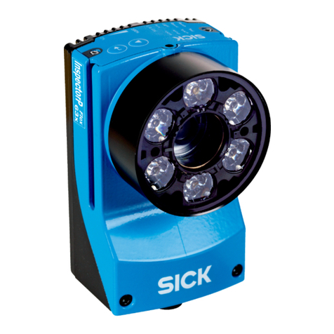
SICK InspectorP63 Flex C-mount Series User manual

OPERATING INSTRUCTIONS
InspectorP63x Flex C-mount and S-mount
2D machine vision

Described product
InspectorP63x Flex C-mount
InspectorP63x Flex S-mount
Manufacturer
SICK AG
Erwin-Sick-Str. 1
79183 Waldkirch
Germany
Legal information
This work is protected by copyright. Any rights derived from the copyright shall be
reserved for SICK AG. Reproduction of this document or parts of this document is
only permissible within the limits of the legal determination of Copyright Law. Any modi‐
fication, abridgment or translation of this document is prohibited without the express
written permission of SICK AG.
The trademarks stated in this document are the property of their respective owner.
© SICK AG. All rights reserved.
Original document
This document is an original document of SICK AG.
2O P E R A T I N G I N S T R U C T I O N S | InspectorP63x Flex C-mount and S-mount 8019946/1EJ6/2022-02 | SICK
Subject to change without notice

Contents
1 About this document........................................................................ 5
1.1 Information on the operating instructions.............................................. 5
1.2 Scope......................................................................................................... 5
1.3 Explanation of symbols............................................................................ 5
1.4 Further information................................................................................... 6
2 Safety information............................................................................ 7
2.1 Intended use............................................................................................. 7
2.2 Improper use............................................................................................. 7
2.3 Limitation of liability................................................................................. 8
2.4 Modifications and conversions................................................................ 8
2.5 Cybersecurity............................................................................................ 8
2.6 Requirements for skilled persons and operating personnel.................. 9
2.7 Operational safety and particular hazards.............................................. 9
3 Product description........................................................................... 12
3.1 Scope of delivery....................................................................................... 12
3.2 Product ID.................................................................................................. 13
3.3 Product characteristics............................................................................ 15
3.4 SICK AppSpace......................................................................................... 18
4 Transport and storage....................................................................... 19
4.1 Transport................................................................................................... 19
4.2 Transport inspection................................................................................. 19
4.3 Storage...................................................................................................... 19
5 Mounting............................................................................................. 20
5.1 Overview of mounting procedure............................................................. 20
5.2 Preparation for mounting......................................................................... 20
5.3 Mount the optics....................................................................................... 21
5.4 Mounting location..................................................................................... 25
5.5 Mounting the device................................................................................. 31
6 Electrical installation........................................................................ 33
6.1 Wiring instructions.................................................................................... 33
6.2 Prerequisites for safe operation of the device........................................ 34
6.3 Connection diagrams............................................................................... 37
6.4 Connections and pin assignment............................................................ 38
6.5 Connecting the device.............................................................................. 38
7 Commissioning.................................................................................. 43
7.1 Installing SensorApps and programming the device.............................. 43
8 Maintenance...................................................................................... 45
8.1 Maintenance plan..................................................................................... 45
CONTENTS
8019946/1EJ6/2022-02 | SICK O P E R A T I N G I N S T R U C T I O N S | InspectorP63x Flex C-mount and S-mount 3
Subject to change without notice

8.2 Cleaning..................................................................................................... 45
8.3 Repairs...................................................................................................... 46
9 Troubleshooting................................................................................. 47
9.1 Overview of possible errors and faults.................................................... 47
9.2 Detailed fault analysis.............................................................................. 47
9.3 SICK service.............................................................................................. 47
9.4 Repairs...................................................................................................... 47
9.5 Returns...................................................................................................... 47
10 Decommissioning............................................................................. 49
10.1 Disposal..................................................................................................... 49
11 Technical data.................................................................................... 50
11.1 Optics and Illumination............................................................................ 50
11.2 Performance............................................................................................. 50
11.3 Interfaces.................................................................................................. 51
11.4 Mechanics and electronics...................................................................... 51
11.5 Ambient data............................................................................................. 52
12 Accessories........................................................................................ 53
13 Annex.................................................................................................. 54
13.1 Declarations of conformity and certificates............................................ 54
13.2 Licenses.................................................................................................... 54
13.3 Connection diagrams of connection module CDB650-204.................. 54
13.4 Connection diagrams of connection module CDM420-0006............... 64
CONTENTS
4O P E R A T I N G I N S T R U C T I O N S | InspectorP63x Flex C-mount and S-mount 8019946/1EJ6/2022-02 | SICK
Subject to change without notice

1 About this document
1.1 Information on the operating instructions
These operating instructions provide important information on how to use devices from
SICK AG.
Prerequisites for safe work are:
•Compliance with all safety notes and handling instructions supplied.
•Compliance with local work safety regulations and general safety regulations for
device applications
The operating instructions are intended to be used by qualified personnel and electrical
specialists.
NOTE
Read these operating instructions carefully to familiarize yourself with the device and its
functions before commencing any work.
The instructions constitute an integral part of the product and are to be stored in the
immediate vicinity of the device so they remain accessible to staff at all times. Should
the device be passed on to a third party, these operating instructions should be handed
over with it.
These operating instructions do not provide information on operating the machine
or system in which the device is integrated. For information about this, refer to the
operating instructions of the specific machine.
1.2 Scope
These operating instructions serve to incorporate the device into a customer system.
Instructions are given by stages for all actions required.
These operating instructions apply to all available device types of the product. To obtain
more detailed information on identifying your device type, see "Type code", page 13.
Available device types are listed on the online product page:
•www.sick.com/InspectorP63x
A number of device types are used as examples for commissioning and based on the
default parameter settings for the relevant device.
1.3 Explanation of symbols
Warnings and important information in this document are labeled with symbols. Sig‐
nal words introduce the instructions and indicate the extent of the hazard. To avoid
accidents, damage, and personal injury, always comply with the instructions and act
carefully.
DANGER
… indicates a situation of imminent danger, which will lead to a fatality or serious
injuries if not prevented.
WARNING
… indicates a potentially dangerous situation, which may lead to a fatality or serious
injuries if not prevented.
ABOUT THIS DOCUMENT 1
8019946/1EJ6/2022-02 | SICK O P E R A T I N G I N S T R U C T I O N S | InspectorP63x Flex C-mount and S-mount 5
Subject to change without notice

CAUTION
… indicates a potentially dangerous situation, which may lead to minor/slight injuries if
not prevented.
NOTICE
… indicates a potentially harmful situation, which may lead to material damage if not
prevented.
NOTE
… highlights useful tips and recommendations as well as information for efficient and
trouble-free operation.
1.4 Further information
NOTE
Further documentation for the device can be found on the online product page at:
•www.sick.com/InspectorP63x
There, additional information has been provided depending on the product, such as:
•Model-specific online data sheets for device types, containing technical data,
dimensional drawing, and specification diagrams
•Declarations of conformity and certificates of the product family
•Dimensional drawings and 3D CAD dimension models of the device types in
various electronic formats
•Other publications related to the devices described here
•Publications dealing with accessories
NOTE
Important information about the integratable VI55I illumination unit can be found
in the “VI55I ring illumination unit” technical information (part number: 8018486,
www.sick.com/8018486).
1 ABOUT THIS DOCUMENT
6O P E R A T I N G I N S T R U C T I O N S | InspectorP63x Flex C-mount and S-mount 8019946/1EJ6/2022-02 | SICK
Subject to change without notice

2 Safety information
2.1 Intended use
The InspectorP6xx is a programmable vision sensor for industrial use for tasks which
require high-resolution images at long distances.
The device is programmed on a PC by using the development environment software
SICK AppSpace. Depending on the application, a browser-based, graphical user inter‐
face (GUI) can be created, which provides opportunities defined by the application
developer to influence an application at operator level. The device offers various inter‐
faces for controlling, programming, and operating purposes, which can be activated
as necessary via development environments, control systems (programmable logic
controllers), or applications. However, configuration, programming, and control requires
various technical skills, depending on how the device is connected and used.
The devices are primarily designed for use in industrial and logistics areas, and they
meet the requirements for industrial ruggedness, interfaces and data processing. They
are not safety components as per the Machinery Directive 2006/42/EC. They are
not intended and not permitted to be used in areas with explosive atmospheres, in
corrosive environments, or in extreme ambient conditions.
2.1.1 Conditions for specified enclosure rating
To ensure compliance with the specified enclosure rating of the device during opera‐
tion, the following requirements must be met: If these requirements are not met, the
device does not fulfill any specified enclosure rating.
•The cables plugged into the electrical connections must be screwed tight.
•Any electrical connections that are not being used must be sealed with a tightly-
fastened protective cap (as in the delivery condition).
•The foldable cover must be flush with the device and screwed tight.
•The optics protection hood must be screwed tightly onto the device.
2.1.2 Cover on the device
NOTICE
Risk of product damage if cover is open!
In open state, the device does not conform to a specified enclosure rating.
If necessary, only operate the device for a short time with an open cover for the
activities listed in the following: During this time, protect the device against moisture
and dust.
Briefly open the cover for the following activities:
•Inserting or removing the optional memory card
For further warranty provisions, see the General Terms and Conditions of SICK AG, e.g.,
on the delivery note of the device.
2.2 Improper use
Any use outside of the stated areas, in particular use outside of the technical specifica‐
tions and the requirements for intended use, will be deemed to be incorrect use.
•The device does not constitute a safety component in accordance with the respec‐
tive applicable safety standards for machines.
•The device must not be used in explosion-hazardous areas, in corrosive environ‐
ments or under extreme environmental conditions.
•Any use of accessories not specifically approved by SICK AG is at your own risk.
SAFETY INFORMATION 2
8019946/1EJ6/2022-02 | SICK O P E R A T I N G I N S T R U C T I O N S | InspectorP63x Flex C-mount and S-mount 7
Subject to change without notice

WARNING
Danger due to improper use!
Any improper use can result in dangerous situations.
Therefore, observe the following information:
■Product should be used only in accordance with its intended use.
■All information in these operating instructions must be strictly observed.
■Shut down the product immediately in case of damage.
2.3 Limitation of liability
Relevant standards and regulations, the latest technological developments, and our
many years of knowledge and experience have all been taken into account when
compiling the data and information contained in these operating instructions. The
manufacturer accepts no liability for damage caused by:
■Non-adherence to the product documentation (e.g., operating instructions)
■Incorrect use
■Use of untrained staff
■Unauthorized conversions or repair
■Technical modifications
■Use of unauthorized spare parts, consumables, and accessories
2.3.1 Programmable device
The InspectorP6xx is a programmable device.
Therefore the respective programmer is responsible for his/her programming perform‐
ance and the resulting working principle of the device.
The liability and warranty of SICK AG is limited to the device specification (hardware
functionality and any programming interfaces) according to the agreed conditions.
Therefore, SICK AG is not liable, among other things, for damages that are caused by
programming of the customer or third parties.
2.4 Modifications and conversions
NOTICE
Modifications and conversions to the device may result in unforeseeable dangers.
Interrupting or modifying the device or SICK software will invalidate any warranty claims
against SICK AG. This applies in particular to opening the housing, even as part of
mounting and electrical installation.
2.5 Cybersecurity
To protect against cybersecurity threats, it is necessary to continuously monitor and
maintain a comprehensive and holistic cybersecurity concept. A suitable concept com‐
prises organizational, technical, procedural, electronic, and physical levels of defense
and provides suitable measures for different types of risks. SICK's products and solu‐
tions must be viewed as a component of this concept.
Information on Cybersecurity can be found at: www.sick.com/psirt .
2 SAFETY INFORMATION
8O P E R A T I N G I N S T R U C T I O N S | InspectorP63x Flex C-mount and S-mount 8019946/1EJ6/2022-02 | SICK
Subject to change without notice

2.6 Requirements for skilled persons and operating personnel
WARNING
Risk of injury due to insufficient training.
Improper handling of the device may result in considerable personal injury and material
damage.
■All work must only ever be carried out by the stipulated persons.
This product documentation refers to the following qualification requirements for the
various activities associated with the device:
■Instructed personnel have been briefed by the operator about the tasks assigned
to them and about potential dangers arising from improper action.
■Skilled personnel have the specialist training, skills, and experience, as well as
knowledge of the relevant regulations, to be able to perform tasks delegated to
them and to detect and avoid any potential dangers independently.
■Electricians have the specialist training, skills, and experience, as well as knowl‐
edge of the relevant standards and provisions to be able to carry out work on
electrical systems and to detect and avoid any potential dangers independently.
In Germany, electricians must meet the specifications of the BGV A3 Work Safety
Regulations (e.g. Master Electrician). Other relevant regulations applicable in other
countries must be observed.
The following qualifications are required for various activities:
Table 1: Activities and technical requirements
Activities Qualification
Mounting, maintenance ■Basic practical technical training
■Knowledge of the current safety regulations in the workplace
Electrical installation,
device replacement
■Practical electrical training
■Knowledge of current electrical safety regulations
■Knowledge of the operation and control of the devices in their
particular application
Commissioning, configura‐
tion
■Basic knowledge of the WindowsTM operating system in use
■Basic knowledge of the design and setup of the described
connections and interfaces
■Basic knowledge of data transmission
■Knowledge of the programming of image-processing systems
and network components
Operation of the device for
the particular application
■Knowledge of the operation and control of the devices in their
particular application
■Knowledge of the software and hardware environment for the
particular application
2.7 Operational safety and particular hazards
Please observe the safety notes and the warnings listed here and in other chapters
of this product documentation to reduce the possibility of risks to health and avoid
dangerous situations.
LED radiation of the integratable illumination unit
NOTICE
Only the VI55I illumination units from SICK intended for integration in this application
can be used as integratable illumination units.
SAFETY INFORMATION 2
8019946/1EJ6/2022-02 | SICK O P E R A T I N G I N S T R U C T I O N S | InspectorP63x Flex C-mount and S-mount 9
Subject to change without notice

Risk group 1
•Color of the illumination: visible blue light (aperture angle: wide, medium), visible
red light or visible white light
•Color of the feedback LED: visible red light and visible green light
CAUTION
Optical radiation: LED risk group 1, visible radiation, 400 nm to 780 nm
The LEDs may pose a danger to the eyes in the event of incorrect use.
■Do not look into the light source intentionally.
■Do not open the housing. Opening the housing will not switch off the light source.
Opening the housing may increase the level of risk.
■Comply with the current national regulations on photobiological security of lamps
and lamp systems.
Risk group 2
•Color of the illumination: visible blue light (aperture angle: narrow)
CAUTION
Warning! Optical radiation: LED risk group 2, visible radiation, 400 nm to 780 nm
Potentially dangerous optical radiation. Can be damaging to the eyes.
■Do not look into the light source for extended periods of time.
■Never point the light source at people.
■Avoid any reflections on people from reflective surfaces. Be particularly careful
during mounting and alignment work.
■Do not open the housing. Opening the housing will not switch off the light source.
Opening the housing may increase the level of risk.
■Comply with the current national regulations on photobiological security of lamps
and lamp systems.
If the product is operated in conjunction with external illumination systems, the risks
described here may be exceeded. This must be taken into consideration by users on a
case-by-case basis.
CAUTION
Optical radiation: Class 1 Laser Product
The accessible radiation does not pose a danger when viewed directly for up to 100
seconds. It may pose a danger to the eyes and skin in the event of incorrect use.
■Do not open the housing. Opening the housing may increase the level of risk.
■Current national regulations regarding laser protection must be observed.
For both radiation types:
It is not possible to entirely rule out temporary disorienting optical effects, particularly
in conditions of dim lighting. Disorienting optical effects may come in the form of
dazzle, flash blindness, afterimages, photosensitive epilepsy, or impairment of color
vision, for example.
2 SAFETY INFORMATION
10 O P E R A T I N G I N S T R U C T I O N S | InspectorP63x Flex C-mount and S-mount 8019946/1EJ6/2022-02 | SICK
Subject to change without notice

WARNING
Electrical voltage!
Electrical voltage can cause severe injury or death.
■Work on electrical systems must only be performed by qualified electricians.
■The power supply must be disconnected when attaching and detaching electrical
connections.
■The product must only be connected to a voltage supply as set out in the require‐
ments in the operating instructions.
■National and regional regulations must be complied with.
■Safety requirements relating to work on electrical systems must be complied with.
WARNING
Risk of injury and damage caused by potential equalization currents!
Improper grounding can lead to dangerous equipotential bonding currents, which may
in turn lead to dangerous voltages on metallic surfaces, such as the housing. Electrical
voltage can cause severe injury or death.
■Work on electrical systems must only be performed by qualified electricians.
■Follow the notes in the operating instructions.
■Install the grounding for the product and the system in accordance with national
and regional regulations.
SAFETY INFORMATION 2
8019946/1EJ6/2022-02 | SICK O P E R A T I N G I N S T R U C T I O N S | InspectorP63x Flex C-mount and S-mount 11
Subject to change without notice

3 Product description
3.1 Scope of delivery
Depending on the chosen device version, the scope of delivery of the device will include
the following components:
Table 2: Scope of delivery
No. of
units
Component Remarks
1 Type of device ordered (com‐
plete device or basic device)
Complete device:
•Components are assembled at the factory (cam‐
era housing and optics accessories).
•Optics protection hood is provided with a device
seal.
Basic device:
•Mount camera housing and individual compo‐
nents on your own.
•Order individual components separately as
accessories .
•Light inlet is sealed with a protective cap.
All devices:
•Electrical connections are sealed with protective
caps.
•Without holders and connecting cables
2 Sliding nut, 5.5 mm deep, with
M5 threaded fixing hole
•Alternative mounting option for the device
instead of the threaded mounting hole
•Use in pairs.
1 Hexagon key WAF 2 •S-mount lens: manually adjust focus screw.
•Open and close foldable cover (access to the
microSD card slot and the focus screw).
2 Blue label (round, self-adhesive) •Protection of adjusted focus setting (S-mount
lens)
•After adjustment of the focus setting, the label
can be stuck over the access opening for the
focus adjustment screw.
•1 label as spare part
1 SICK lens cloth Clean optical surfaces (e.g. front screen in the
optics protection hood).
1 Printed safety notes, multilin‐
gual
Brief information and general safety notes
Quality Inspection SensorApp Pre-installed on the device
1) Depending on order, e.g. lens, integratable VI55I illumination unit, spacers, optics protection hood.
Associated components not contained in the delivery:
Table 3: Other components
Component Remarks
SOPAS ET configuration software Available online at:
•www.sick.com/SOPAS_ET
SICK AppStudio software Available online at:
•www.sick.com/SICK_AppStudio
SICK AppManager software Available online at:
•www.sick.com/SICK_AppManager
3 PRODUCT DESCRIPTION
12 O P E R A T I N G I N S T R U C T I O N S | InspectorP63x Flex C-mount and S-mount 8019946/1EJ6/2022-02 | SICK
Subject to change without notice

Component Remarks
This documentation, available in English,
German and French, and in other lan‐
guages if necessary
Available online at:
•www.sick.com/InspectorP63x
An overview of available complete devices and a selection guide for the matching
device components for the basic devices is provided on the online product page.
Accessories
Accessories are only supplied if you order them separately, see "Accessories",
page 53.
3.2 Product ID
3.2.1 Type label
The type label gives information for identification of the sensor.
UL certification is dependent on the type. Information on the existing UL certification
can be found on the type label.
1
2
3
4
5
6
Figure 1: Type label design for the sensor
1Type code
2Product identification number
3Serial number
4Power consumption
5MAC address
6Date of manufacture
3.2.2 Type code
V 2 D 6 x x P - x M x x x x x
1 2 3 4 5 6 7 8 9 10 11 12 13 14
Position Description
1–5 Product family
V2D63 InspectorP63x
6Image sensor resolution
1: 1.3 megapixels (1,280 px x 1,024 px)
2: 1.9 megapixels (1,600 px x 1,200 px)
7Function
P: Programmable
8Generation
9Image sensor type
M: Monochrome
PRODUCT DESCRIPTION 3
8019946/1EJ6/2022-02 | SICK O P E R A T I N G I N S T R U C T I O N S | InspectorP63x Flex C-mount and S-mount 13
Subject to change without notice

Position Description
10 Illumination
X: No illumination unit installed
I: White, wide
K: White, medium
W: White, narrow
N: Blue, wide
P: Blue, medium
B: Blue, narrow
11–12 Lens type and f-number
CX c-mount module, no lens
Variants with c-mount lens:
CA 6 mm (f1.4–16)
CB 8 mm (f1.4–16)
CD 12 mm (f1.4–16)
CE 15 mm (f1.4–16)
CF 25 mm (f1.4–16)
CG 35 mm (f1.4–16)
CH 50 mm (f1.4–16)
Variants with compact c-mount lens:
MD 12 mm (f8)
ME 16 mm (f8)
MF 25 mm (f8)
MG 35 mm (f8)
MI 12 mm (f11)
MK 16 mm (f11)
ML 25 mm (f11)
MM 35 mm (f11)
SX s-mount module, no lens
Variants with s-mount lens:
SC 9.6 mm (f8)
SD 12.5 mm (f8)
SE 17.5 mm (f8)
SF 25 mm (f8)
13 Connection variants1)
B: Stand-alone USB, CAN, Serial, I/O, Ethernet
14 IP protection class and front screen
5: IP 67: plastic front screen
6: IP 67: glass front screen
1) see "Connections and pin assignment", page 38
3 PRODUCT DESCRIPTION
14 O P E R A T I N G I N S T R U C T I O N S | InspectorP63x Flex C-mount and S-mount 8019946/1EJ6/2022-02 | SICK
Subject to change without notice

3.3 Product characteristics
3.3.1 Device view
Dimensional drawing
59.1
45.8
min. 8 – max. 50
91.8
5.9
6.5 50
23.9
0.5
74.1
63.1
76.6
108
10.8
1 2
3
4
5
6
7
89
äå
æ
ç
ã
ß
àá
â
96.4
1External illumination connection
2Gigabit Ethernet port
3USB port
4Power, serial, CAN, and I/O connection
522.7 mm, 37.7 mm, or 60 mm protective optics cover
6Protective caps/plugs to seal any electrical connections that are not in use
7M5 blind tapped holes, 5.5 mm deep (4 x), for mounting the sensor
8M5 sliding nut, 5.5 mm deep (4 x), pivoting, for an alternative method of mounting the
sensor
9Integrable illumination connection
ßAiming laser (2 x)
àS-mount or C-mount optics module
á2.5 mm blind tapped holes (4 x) for mounting the spacers for the integrable illumination
âOptical axis and center of the image sensor
ãManual focus screw, underneath cover/label (S-mount)
äFunction button (2 x)
åLED bar graph (5 x)
æRemovable cover for microSD card and manual focus screw (S-mount)
çLEDs for status display (5 x 2 levels)
PRODUCT DESCRIPTION 3
8019946/1EJ6/2022-02 | SICK O P E R A T I N G I N S T R U C T I O N S | InspectorP63x Flex C-mount and S-mount 15
Subject to change without notice

Integrable illumination unit (option)
1
2
3
1
2
1Illumination via 6 LEDs
22 openings in the illumination for the aiming laser for alignment: the red laser LEDs can
be switched off and each generates a red dot on the object within the field of view
3Feedback LED, green (pass) or red (fail), can be switched via software, after a successful
analysis (default), it briefly generates a light spot on the object within the field of view
3.3.2 Status indicators and functions
0%
100%
Ready
Result
|Test
|Teach
|Focus
|Setup
L/A GbE
Func
Light
1 2
1Skip button
2Enter button
See table 4 for LED descriptions. The functions for the programmable LEDs are defined
by the user in the SICK AppStudio software.
Table 4: LED status descriptions
Display LED Color Status
Ready green Sensor ready
yellow Firmware or SensorApps are
being installed on the device.
Do not disconnect the power to
the device.
red Hardware or software error
Result Programmable red, green, blue, fuchsia,
yellow, aqua, white
Function defined by user
Light Programmable red, green, blue, fuchsia,
yellow, aqua, white
Function defined by user
Function Programmable red, green, blue, fuchsia,
yellow, aqua, white
Function defined by user
L/A GbE green The device is connected to a
network
LED bar
graph (0 - 4)
Programmable red, green, blue, fuchsia,
yellow, aqua, white
Function for each LED defined
by user
= illuminated, = flashing
3.3.3 Product features and functionality
The InspectorP6xx is a vision sensor which is well-suited for a wide variety of industrial
tasks thanks to its programmable interface.
3 PRODUCT DESCRIPTION
16 O P E R A T I N G I N S T R U C T I O N S | InspectorP63x Flex C-mount and S-mount 8019946/1EJ6/2022-02 | SICK
Subject to change without notice

Convenient functions such as function buttons, auto-setup, aiming laser, an acoustic
feedback signal, and a green feedback LED reduce the amount of work required for
training and installation.
The microSD memory card can be used to store images or backup copies of parame‐
ters. Thanks to SICK's 4Dpro feature, the InspectorP6xx can be integrated into numer‐
ous industrial networks.
3.3.4 Memory card
The device has a card slot integrated in the housing. The card slot accommodates a
memory card in microSD format.
NOTE
The microSD memory card is optional and not included in the scope of delivery of the
device. The device supports memory cards up to max. 32 GB.
Only use types (industrial standard) approved by SICK to ensure reliable function of the
memory card. You can find these as accessories online at:
•www.sick.com/InspectorP63x
The memory card has no write protection that can be activated.
Inserting the memory card in the device:
NOTICE
Risk of damage to the memory card!
bTo avoid damaging the microSD memory card, make sure the device is de-ener‐
gized when you insert or remove the card. For this purpose, disconnect the device
from the supply voltage.
Access to the card slot
The card slot for the memory card is located under the hinged cover on the top side of
the device.
1. Switch off the supply voltage to the device.
2. Undo the screws (SW2 hexagon key) on the hinged cover and open the cover as
follows:
°Carefully pull the upper edge of the cover away from the housing a little at the
level of the hinges on the side. Use both of the recesses on the inside of the
cover to do this.
°Fold the cover upwards starting from the bottom edge.
3. Making sure it is in the correct position, insert the memory card into the slot until
it locks into place. When doing this, position the contacts so that they are facing to
the rear and upwards, see the card symbol on the device.
4. Close the hinged cover. Make sure that the cover is completely flush with the
housing.
5. Tighten the screws on the hinged cover again.
6. Switch on the supply voltage for the device.
PRODUCT DESCRIPTION 3
8019946/1EJ6/2022-02 | SICK O P E R A T I N G I N S T R U C T I O N S | InspectorP63x Flex C-mount and S-mount 17
Subject to change without notice

Removing the memory card from the device:
NOTICE
Risk of damage to the memory card!
bTo avoid damaging the microSD memory card, make sure the device is de-ener‐
gized when you insert or remove the card. For this purpose, disconnect the device
from the supply voltage.
1. Switch off the supply voltage to the device.
2. Undo the screws on the hinged cover.
3. Making sure it is in the correct position, push the memory card into the slot until
it is released. When doing this, position the contacts so that they are facing to the
rear and upwards, see the card symbol on the device.
4. Remove the memory card.
5. Close the hinged cover. Make sure that the cover is completely flush with the
housing.
6. Tighten the screws on the hinged cover.
7. Switch on the supply voltage for the device.
3.4 SICK AppSpace
The InspectorP6xx product family is part of the SICK AppSpace ecosystem, which
consists of software tools and programmable sensors or devices. See figure 2 for an
overview of SICK AppSpace.
Support
Portal
PROGRAMMABLE DEVICES
TOOLS
APP DEVELOPERS
Sensor
AppPool
SensorApps
AM
AppManagerAppStudio
AS
Conference Sensor Integration
Machine
Figure 2: SICK AppSpace
SICK AppSpace includes the following components and resources:
•SICK AppManager: A software tool used for the installation and management of
SensorApps and device firmware updates.
•SICK AppPool: A cloud-based repository for storing and sharing SensorApps. SICK
AppPool can be accessed directly from SICK AppManager, SICK AppStudio, and
from the web.
•SICK AppStudio: A Software Development Kit (SDK) for developing SensorApps
on programmable SICK devices. Its user interface for machine operators can be
created individually as a web GUI.
•The SICK Support Portal (supportportal.sick.com) contains tutorials and instruc‐
tions for programming the InspectorP6xx in SICK AppStudio.
For more information about downloading SensorApps and programming the device, see
"Commissioning", page 43.
For more information about SICK AppSpace, see www.sick.com/SICK_AppSpace.
3 PRODUCT DESCRIPTION
18 O P E R A T I N G I N S T R U C T I O N S | InspectorP63x Flex C-mount and S-mount 8019946/1EJ6/2022-02 | SICK
Subject to change without notice

4 Transport and storage
4.1 Transport
For your own safety, please read and observe the following notes:
NOTICE
Damage to the product due to improper transport.
■The device must be packaged for transport with protection against shock and
damp.
■Recommendation: Use the original packaging as it provides the best protection.
■Transport should be performed by trained specialist staff only.
■The utmost care and attention is required at all times during unloading and
transportation on company premises.
■Note the symbols on the packaging.
■Do not remove packaging until immediately before you start mounting.
4.2 Transport inspection
Immediately upon receipt in Goods-in, check the delivery for completeness and for any
damage that may have occurred in transit. In the case of transit damage that is visible
externally, proceed as follows:
■Do not accept the delivery or only do so conditionally.
■Note the scope of damage on the transport documents or on the transport compa‐
ny's delivery note.
■File a complaint.
NOTE
Complaints regarding defects should be filed as soon as these are detected. Damage
claims are only valid before the applicable complaint deadlines.
4.3 Storage
Store the device under the following conditions:
■Recommendation: Use the original packaging.
■Do not store outdoors.
■Store in a dry area that is protected from dust.
■So that any residual damp can evaporate, do not package in airtight containers.
■Do not expose to any aggressive substances.
■Protect from sunlight.
■Avoid mechanical shocks.
■Storage temperature: see "Technical data", page 50.
■Relative humidity: see "Technical data", page 50.
■For storage periods of longer than 3 months, check the general condition of all
components and packaging on a regular basis.
TRANSPORT AND STORAGE 4
8019946/1EJ6/2022-02 | SICK O P E R A T I N G I N S T R U C T I O N S | InspectorP63x Flex C-mount and S-mount 19
Subject to change without notice

5 Mounting
5.1 Overview of mounting procedure
The mounting of the device is divided into the following steps:
•Mount the device.
•Align the device with the object.
•Connect the device to interfaces and supply voltage.
•Adjust the device.
5.2 Preparation for mounting
5.2.1 Installation requirements
NOTICE
Radio interference may occur when the device is used in residential areas!
■Only use the device in industrial environments (EN 61000-6-4).
•Typical space requirement: see "Field of view diagrams", page 27 and type-spe‐
cific dimensional drawing
•Comply with the technical data, such as the permitted ambient conditions for
operation, see "Technical data", page 50.
•Ensure good dissipation of excess heat from the device to the surroundings, in
particular at higher ambient temperatures. Ensure that there is good heat transfer
from the device, for example via the bracket to the mounting base, or ensure that
the back of the device is a sufficient distance from the wall of a housing.
•Only mount the device using the threaded mounting holes provided or the movable
sliding nuts.
•Mount the device in a shock and vibration insulated manner.
•Make sure the device has a clear view of the objects to be scanned.
Auxiliary equipment required
■Mounting system with sufficient load-bearing capacity and suitable dimensions
■4 or 2 M5 screws for mounting the device on a mounting system supplied by the
customer
■Tool and tape measure
The screw length depends on the mounting base (wall thickness of the bracket). When
using an optional SICK mounting system, the screws for mounting the device are
included with delivery.
5.2.2 Mounting systems
Mount the device on the mounting system by means of a minimum of two tapped blind
holes (M5) or sliding nuts.
The threaded mounting holes are located on the rear of the device.
The sliding nuts can each be inserted into a slot on the side of the housing.
SICK offers prefabricated mounting brackets that are optimally suited for mounting the
device, see "Accessories", page 53.
Customer-supplied mounting brackets
A customer-supplied mounting bracket must meet the following requirements:
5 MOUNTING
20 O P E R A T I N G I N S T R U C T I O N S | InspectorP63x Flex C-mount and S-mount 8019946/1EJ6/2022-02 | SICK
Subject to change without notice
Other manuals for InspectorP63 Flex C-mount Series
2
This manual suits for next models
2
Table of contents
Other SICK Digital Camera manuals

SICK
SICK ICD880 Series Manual

SICK
SICK EventCam EVC625-CCOXAL5L User manual

SICK
SICK picoCam2 User manual

SICK
SICK ICR880 Generation 3 User manual

SICK
SICK IVC-2D User manual

SICK
SICK ICD890 Manual

SICK
SICK V300 User manual

SICK
SICK InspectorP63 Flex C-mount Series User manual

SICK
SICK midiCam2 User manual

SICK
SICK ICR880 Generation 3 User manual