SICK ICR880 Generation 3 User manual

OPERATING INSTRUCTIONS
ICR880/890
Camera Systems
Camera Systems for Reading 1D/2D Codes with Superb Image
Quality suitable for OCR and Video Coding Applications

Operating Instructions
ICR880/890 Camera Systems
2©SICK AG · Germany · All rights reserved · Subject to change without notice 8011325/XL85/2013-08-20
Software Versions
Software Versions
NOTICE
RF interferences in case of use in residential areas!
The ICR880/890 Camera Systems are exclusively intended for use in industrial areas.
Copyright
Copyright 2006 - 2013
SICK AG Waldkirch
Division Identification & Measuring, Reute plant
Nimburger Strasse 11
79276 Reute
Germany
Trademarks
Windows 2000TM, XPTM, VistaTM and Windows 7TM are registered trademarks or trademarks
of the Microsoft Corporation in the USA and other countries.
AdobeReaderis a trademark of Adobe Systems Incorporated.
Download from the website at the internet: http://get.adobe.com/reader/.
Latest manual version
For the latest version of this manual (PDF), see www.sick.com.
Software/Tool Function Version
ICR880/890 SICK Firmware From V. 3.x
SOPAS-ET*) Configuration software (Windows-based) From V. 2.38
*) runs on a PC under WindowsTM operating system

Operating Instructions
ICR880/890
8011325/XL85/2013-08-20 ©SICK AG · Germany · All rights reserved · Subject to change without notice 3
Contents
Table of Contents
1 Notes on this document ...................................................................................................7
1.1 Purpose...........................................................................................................................7
1.2 Target audience .............................................................................................................8
1.3 Information content .......................................................................................................8
1.4 Symbols used .................................................................................................................9
2 Safety information ......................................................................................................... 11
2.1 Authorized users ......................................................................................................... 11
2.2 Intended use................................................................................................................ 11
2.3 General safety precautions and protection measures ............................................. 12
2.4 Quick stop and quick start.......................................................................................... 15
2.5 Environmental information......................................................................................... 15
3 Product description ........................................................................................................ 17
3.1 Design of the Camera System.................................................................................... 17
3.2 System requirements.................................................................................................. 21
3.3 Product features and functions (overview) ............................................................... 23
3.4 Method of operation ................................................................................................... 24
3.5 Indicators and control elements ................................................................................ 32
4 Installation....................................................................................................................... 35
4.1 Overview of installation sequence ............................................................................. 35
4.2 Installation preparations ............................................................................................ 35
4.3 Installing and adjusting the Camera System ............................................................ 38
4.4 Installing external components.................................................................................. 41
4.5 Removing the device................................................................................................... 42
5 Electrical installation ..................................................................................................... 43
5.1 Overview of installation sequence ............................................................................. 43
5.2 Electrical installation preparation .............................................................................. 43
5.3 Electrical connections and cables ............................................................................. 48
5.4 Performing electrical installation ............................................................................... 52
5.5 Pin assignments and conductor coloring assignment.............................................. 59
6 Startup and Configuration............................................................................................. 65
6.1 Overview of the startup procedure ............................................................................ 65
6.2 SOPAS-ET Configuration Software ............................................................................. 65
6.3 Establishing communication with the Camera System/MSC800 ........................... 66
6.4 First startup ................................................................................................................. 68
6.5 Default setting ............................................................................................................. 69
7 Maintenance ................................................................................................................... 71
7.1 Maintenance during operation................................................................................... 71
7.2 Cleaning the Camera System..................................................................................... 71
7.3 Replacing a Camera System or a component........................................................... 75
7.4 Disposal ....................................................................................................................... 77
8 Troubleshooting .............................................................................................................. 79
8.1 Overview of errors and malfunctions which could occur.......................................... 79
8.2 Detailed malfunction analysis.................................................................................... 79
8.3 SICK support................................................................................................................ 80
9 Technical data.................................................................................................................81
9.1 Data sheet for ICD880/ICD890 Camera................................................................... 81
9.2 Data sheet for ICI890 Illuminations........................................................................... 83
9.3 Data sheet for deflection mirrors............................................................................... 83
9.4 Specification diagrams ............................................................................................... 84
9.5 ICR880/890 Camera System dimensional drawing................................................. 86
9.6 Deflection mirrors dimensional drawing.................................................................... 88
9.7 EC Declaration of Conformity ..................................................................................... 89
10 Appendix .......................................................................................................................... 91
10.1 Appendix overview ...................................................................................................... 91
10.2 Configuring the Camera System with command strings .......................................... 91

Operating Instructions
ICR880/890 Camera Systems
4©SICK AG · Germany · All rights reserved · Subject to change without notice 8011325/XL85/2013-08-20
Contents
10.3 Ordering information ...................................................................................................92
10.4 Supplementary documentation ..................................................................................92
10.5 Glossary........................................................................................................................93
10.6 Tables and Figures ......................................................................................................96

Operating Instructions
ICR880/890
T
ables and Figures
8011325/XL85/2013-08-20 ©SICK AG · Germany · All rights reserved · Subject to change without notice 5
Abbreviations
For a list of tables and figures see Chapter 10.6, Page 96.
BMP Bitmap(pixel-oriented Windows format for saving photos)
CAN Controller Area Network (field bus protocol based on the CAN bus)
CMOS Complementary metal–oxide–semiconductor
DOF Depth Of Field
dpi dots per inch (1 inch = 25.4 mm)
EEPROM Electrically Erasable Programmable Read Only Memory
FIFO First In First Out
FTP File Transfer Protocol
HTML Hyper Text Markup Language
IInput
ICD Image Capture Device
ICI Image Capture Illumination
ICR Image Code Reader (High-end CMOS Camera System)
JPEG Joint Photographic Expert Group (pixel-oriented file format for saving high compression photos,
compression process for tiff formats)
LED Light Emitting Diode
LIFO Last In First Out
lpi Lines per inch (1 inch = 25.4 mm)
MAC Medium Access Control
MLG Modular Light Grid
MSC Modular System Controller (MSC800)
MTBF Mean Time Between Failure
MTTR Mean Time To Repair
OOutput
OCR Optical Character Recognition
PLC Programmable Logic Controllers
RAM Random Access Memory
RoHS Restriction of (the use of certain) Hazardous Substances
ROM Read Only Memory
SD Secure Digital Card
SMART SICK Modular Advanced Recognition Technology
SOPAS-ET SICK Open Portal for Application and Systems Engineering Tool (PC software for Windows for
configuration of the ICR86x System and the MSC800)
TCP/IP Transmission Control Protocol/Internet Protocol
UDP User Datagram Protocol
VCS Video Coding System
VMS Volume Measuring System

Operating Instructions
ICR880/890 Camera Systems
6©SICK AG · Germany · All rights reserved · Subject to change without notice 8011325/XL85/2013-08-20
Tables and Figures
Notes:

Operating Instructions Chapter 1
ICR880/890
Notes on this document
8011325/XL85/2013-08-20 ©SICK AG · Germany · All rights reserved · Subject to change without notice 7
1Notes on this document
1.1 Purpose
This document provides instructions for technical staff on the installation and operation of
the Camera Systems in the ICR880/890 series with focus control and the following variants
of system components:
–System 1:
ICD880 Camera with standard lens (focal distance 80 mm (3.15 in)) and ICI890-x11xx
illumination (length 750 mm (29.5 in))
–System 2:
ICD890 Camera with standard lens (focal distance 135 mm (5.32 in)) and ICI890-
x10xx illumination (length 900 mm (35.4 in))
–System 3:
ICD890 Camera with standard lens (focal distance 135 mm (5.32 in)) and ICI890-
x00xx illumination (length 1,100 mm (43.3 in))
All systems comprise a version of the co-ordinating MSC800 Controller.
A summary of all available Camera System versions is shown in Chapter 3.1.3 Device ver-
sions, Page 20.
This document contains the following information about the Camera Systems:
Safety Information
Installation and electrical installation
Startup and configuration
Maintenance
Product features and functions
Troubleshooting
Replacing system components
Technical data
A step-by-step approach is taken for all tasks.
Important In this document the system components are referred to simplified terms, except where a
distinction of the variants is necessary:
ICR880 or ICR890 Camera System, simplified: Camera System
ICD800 or ICD890 Image Capture Device, simplified: Camera
ICI890 Image Capture Illumination, simplified: ICI890 Illumination
MSC800 Modular System Controller, simplified: MSC800
MLG Light Grid (Modular Light Grid), simplified: MLG Light Grid
VMS4xx/5xx Volume Measuring System, simplified: VMS4xx/5xx
SICK Open Portal for Application and Systems Engineering Tool, simplified:
SOPAS-ET Configuration Software
The register tabs for configuration of the Camera Systems and the MSC800 are re-
ferred to in the SOPAS-ET Configuration Software online help as "device pages".
1D codes generally mean bar codes also called linear codes.
2D codes generally mean stacked codes and matrix codes. Chapter 9 Technical data,
Page 81 lists the code types readable by the Camera System.

Chapter 1Operating Instructions
ICR880/890 Camera Systems
8©SICK AG · Germany · All rights reserved · Subject to change without notice 8011325/XL85/2013-08-20
Notes on this document
1.2 Target audience
The target audience of this document is persons assigned the following tasks:
1.3 Information content
This document contains all the required information for installation, electrical installation
and operation of the ICR880/890 Camera Systems at the installation location. The factory
configuration (default setting) of the Camera Systems as a stand-alone device is optimized
to a single-side reading (from above or from the side).
Configuration of the Camera Systems for the application-specific reading conditions and
operation is carried out via the SOPAS-ET Configuration Software at a WindowsTM-PC. The
SOPAS-ET Configuration Software contains an online help system to facilitate configuration.
Installation and electrical installation of the MSC800 controller and its configuration is de-
tailed in the MSC800 Operating Instructions (part no. 8011540). These instructions also
described use of the MSC800 as a controller for a multi-side reading.
Important This document only describes customer-specific devices (hardware or functional modified)
in the parts which mets the standard devices.
Further information on Camera Systems, Volume Measurement Systems and 1D/2D Code
Scanners is available from SICK AG, Division Identification & Measuring.
On the Internet at www.sick.com.
Tasks Target audience
Installation, electrical installation, main-
tenance, replacing system components
Qualified staff, e.g. service technicians and factory elec-
tricians
Startup and configuration Qualified staff, e.g. technicians and engineers
Operation of the conveyor system Qualified staff for startup and operation of the conveyor
system
Tab. 1-1: Target audience of the document
Operating Instructions Chapter 1
ICR880/890
Notes on this document
8011325/XL85/2013-08-20 ©SICK AG · Germany · All rights reserved · Subject to change without notice 9
1.4 Symbols used
Some of the information in this document is marked specially so that you can access it
quickly:
NOTICE
Notice!
Indicates a potential risk of damage or impair on the functionality of the Camera System.
WARNING
Warning notice!
A warning noctice indicates real or potential danger. This should protect you against acci-
dents.
The safety symbol next to the warning notice indicates why there is a risk of accident. e.g.
due to electricity. The warning levels (CAUTION, WARNING, DANGER) indicate the serious-
ness of the risk.
Carefully read and follow the warning notices.
Reference Italics are used to refer to more detailed information elsewhere.
Important his important note informs you about specific features.
Explanation Explanations provide background information on technical correlations.
Recommendation Recommendations help you carry out certain procedures more effectively.
TIP Tips explain settings in the SOPAS-ET Configuration Software.
PROJECT This font indicates a term in the user interface of the SOPAS-ET Configuration Software.
Icons refer to buttons in the user interface of the SOPAS-ET Configuration Software.
"0x0" This font indicates messages output by the Camera System.
This symbol identifies sections that describe steps carried out with the SOPAS-ET Configu-
ration Software.
This symbol refers to additional technical documentation.
There is a procedure which needs to be carried out. This symbol indicates operational in-
structions which only contain one operational step or operational steps in warning notices
which do not have to be followed in any particular order.
Operational instructions comprising several steps in definite order are denoted using con-
secutive numbers.
This symbol indicates a glossary entry.

Chapter 1Operating Instructions
ICR880/890 Camera Systems
10 ©SICK AG · Germany · All rights reserved · Subject to change without notice 8011325/XL85/2013-08-20
Notes on this document
Notes:

Operating Instructions Chapter 2
ICR880/890
Safety information
8011325/XL85/2013-08-20 ©SICK AG · Germany · All rights reserved · Subject to change without notice 11
2Safety information
This chapter deals with your safety and operator safety of the conveyor system.
Read this chapter carefully before using the Camera Systems.
2.1 Authorized users
For correct and safe functioning, the Camera System must be installed, operated and main-
tained by sufficiently qualified staff.
NOTICE
Risk of damage!
Repairs to the ICR880/890 Camera Systems should only be carried out by qualified and au-
thorized SICK AG service staff.
The operating instructions should be made available to the end user.
The end user should be briefed and urged to read the operating instructions by the
technicians.
The following chapters summarize the required qualifications for the various tasks.
2.2 Intended use
The ICR880/890 Camera System is an intelligent sensor for the recognition and decoding
of 1D/2D codes on moving objects in a reading station. In combination with the co-ordinat-
ing MSC800 modular system controller and further system components the Camera System
presents an automatic reading system.
With the MSC800 modular system controller, the Camera System is used as a stand-alone
device for single-side reading, e.g. from above or from the side. For a similarly possible
multi-side reading on the conveyor system, the corresponding number of Camera Systems
is combined with other SICK bar code scanners and with the MSC800.
The intended use of the Camera System results from the following description of the system
components and their functions:
Tasks Qualification
Installation, maintenance – Practical technical training
– Knowledge of current health and safety regulations at the work-
place
Electrical installation,
replacing the device
– Practical electrical training
– Knowledge of current electrical safety regulations
– Knowledge of startup and operation of the device in each operation-
al area (e.g. conveyor system)
Startup and configuration – Basic knowledge of the WindowsTM operating system
– Basic knowledge of designing and setting up (addressing) Ethernet
connections for connecting the Camera System to the Ethernet
– Basic knowledge of data transfer
– Basic knowledge of 1D/2D code technology
Operation of the device in
each operational area
– Knowledge of the mechanical and electrical parameters of the con-
veyor system and the characteristics of the conveyor system regard-
ing startup and operation
– Knowledge of the software and hardware environment in each oper-
ational area (e.g. conveyor system)
Tab. 2-1: Required qualification for starting up the Camera System

Chapter 2Operating Instructions
ICR880/890 Camera Systems
12 ©SICK AG · Germany · All rights reserved · Subject to change without notice 8011325/XL85/2013-08-20
Safety information
Depending on type, the Camera System consists of the ICD880 or ICD890 Camera as
well as of an aligned combination of an ICI890 Illumination variant and an optional de-
flection mirror variant. The Camera is installed in a frame together with the ICI890 Illu-
mination as a unit parallel to the optional deflection mirror, either above the conveyor
system (reading from above) or at the side (side reading).
The necessary object distance information is contained in the Camera System either by
an MLG Light Grid (in the case of readings from above) or by a VMS4xx/5xx Volume
Measurement System for focus control during Single or multi-side reading.
The Camera System transfers the reading data, with optionally selectable diagnosis da-
ta, via the CAN interface to the MSC800. The MSC800 outputs the data via its HOST
data interface (serial RS 232, RS 422/485, Ethernet or CAN) to a superordinate host
processor for further processing.
The processed image information of the Camera is located on two fast GBit Ethernet
channels. The image information can be transferred to the client display at extremely
high data transfer rates on a special PC with compatible GBit Ethernet interface cards.
The high image quality also allows use in OCR and video coding applications.
Configuration/Operation of the Camera System is carried out as standard via the AUX
auxiliary data interface (Ethernet port or serial RS 232) of the MSC800 using the SO-
PAS-ET Configuration Software, which runs on a standard client PC.
Important Any warranty claims against SICK AG shall be deemed invalid in the case of other Camera
System use or Camera System modifications, this includes modifications during installation
and electrical installation or changes to the SICK software. However, the camera or the illu-
mination can be rapidly replaced by the user.
Only operate the Camera System in ambient air temperature limit in indoor areas (see
Chapter 9 Technical data, Page 81).
2.3 General safety precautions and protection measures
Read the general safety precautions thoroughly and observe them during all ICR880/
890 Camera System activities. Also observe the warning notices above the operational
instructions of each chapter.
2.3.1 Radio interferences
NOTICE
RF interferences in case of use in residential areas!
The ICR880/890 Camera Systems are exclusively intended for use in industrial areas.
2.3.2 Installation work
CAUTION
Risk of injuries due to falling components!
Depending on type, the combined weight of the Camera and the ICI890 Illumination is max.
37 kg (81.6 lb.) without installation accessories.
Do not carry out installation work alone.
A second person should always secure components during installation.

Operating Instructions Chapter 2
ICR880/890
Safety information
8011325/XL85/2013-08-20 ©SICK AG · Germany · All rights reserved · Subject to change without notice 13
2.3.3 Electrical installation work
DANGER
Risk of injury by electrical current!
The MSC800 Controller is connected to a mains voltage of 100 V to 264 V AC/50 Hz to
60 Hz.
Observe current safety regulations when working with electrical equipment.
Important Electrical installation should only be carried out by qualified staff.
Connect or disconnect current linkages only under de-energized conditions.
Wire cross sections and their correct protection have to be selected and implemented
according to valid engineering standards. The fuse must be at the beginning of the ca-
ble after the power supply unit.
Connecting a dongle to camera variants with USB connection
Some special camera devices provide an additional USB connection located on the side. In
reading mode, the connection must always be covered by the metal cap (Fig. 2-1).
s
The connection with 2 USB ports (type A sockets) is used for connecting dongles.
Important Other USB capable devices may not be connected.
NOTICE
Risk of damage!
If the USB connection is not handled in correct manner, the electronics of the camera can
be damaged.
Connect or disconnect a dongle to/from the sockets only when the Camera System is
de-energized.
Before connecting or disconnecting a dongle, equipotential bonding must be provided
between the body of the operator and the camera.
During work, wear grounding wrist straps to avoid ESD damage.
In reading mode, only operate the camera with fixed cap of the USB connection due to
the EMC concept.
Fig. 2-1: Location of the optional UBS connection on the side of the camera
Closed USB connection
with fixed metal cap Open USB connection with connected dongle

Chapter 2Operating Instructions
ICR880/890 Camera Systems
14 ©SICK AG · Germany · All rights reserved · Subject to change without notice 8011325/XL85/2013-08-20
Safety information
2.3.4 LED radiation from the ICI890 Illumination
CAUTION
LED radiation!
The Camera Systems ICR880 and ICR890 are classified in LED risk group RG 1 according
to IEC 62471-1:2006-07/EN 62471-1:2008-09. The illumination type-depending uses
LEDs with red, blue or white light.
The entire window surface is the LED radiation outlet opening.
The accessible radiation from the LEDs does not not represent a risk due to the normal re-
strictions imposed by human behavior. It is not possible to entirely rule out temporary, dis-
orientating optical effects on the human eye (e.g. dazzle, flash blindness, afterimages,
impairment of color vision), in particular in conditions of dim lighting. No safety measures
are required.
Caution — use of controls, adjustments or performance of procedures other than those
specified herein may result in hazardous radiation exposure.
Do not deliberately look directly into the illumination for a lengthy period.
Do not open the housing. (The illumination is not switched off if the housing is opened).
Always observe the latest valid version of optical radiation protection regulations for
photobiological safety of lamps and lamp systems.
Radiation power
The ICI890 Illumination type-depending uses LEDs with the following wavelenghts:
Red light: = 620 nm (amber)
Blue and white light: = 470 nm
The radiation emitted is not harmful to human skin.
Important Maintenance is not required to ensure compliance with LED risk group RG 1.
The ICI890 Illumination operates as follows:
The reading pulse (pulse source) controls the on and off mechanism of the LED illumi-
nation during the reading process. The LEDs are switched on in pulsed mode during
the reading operation depending on the reading gate duration.
A time stage (illumination timeout) automatically switches off the illumination during
the reading operation after 3 seconds (default setting) following the start of a continu-
Fig. 2-2: LED radiation outlet opening of the ICI890 Illumination
Output opening

Operating Instructions Chapter 2
ICR880/890
Safety information
8011325/XL85/2013-08-20 ©SICK AG · Germany · All rights reserved · Subject to change without notice 15
ous reading pulse. This, however, does not switch off the reading pulse. The reading
pulse should be stopped via a relevant pulse signal. The next reading pulse switches
the illumination back on.
The illumination timeout can be set or switched off within a range of 3 s to 25 h. For
safety reasons, the minimum illumination power on time is 3 seconds.
2.4 Quick stop and quick start
The Camera System is operated via the MSC800 Controller as standard and can be
switched on and off using the controller main switch.
2.4.1 Switch off the Camera System
Switch off the power supply of the MSC800.
When the Camera System is switched off the following data is lost:
Application-specific parameter sets in the Camera System and in the MSC800 Control-
ler which were only temporarily saved in the devices
The last reading result of the Camera System
Daily operating hours counter of the Camera System
2.4.2 Switch on the Camera System
Switch on the power supply of the MSC800 again.
The Camera System starts up using the most recent permanently saved configuration.
The daily operating hours counter is reset.
2.5 Environmental information
The Camera System has been constructed with minimum environmental pollution in mind.
Excluding the housing, the Camera System does not contain any materials using silicone.
2.5.1 Energy requirements
The Camera System is electrically powered via the MSC800 Controller as standard (func-
tional extra-low voltage in accordance with IEC 60364-4-41). The Camera System and the
logic controller of the MSC800 controller have the following power consumption at 24 V DC
± 20 % and ambient temperature 20 °C (68 °F):
Device type Power consumption
ICR880/890 Camera typical 75 W (via power supply unit of MSC800)
ICI890 illumination
(via power supply unit of MSC800)
Red Illumination (amber):
ICI890-00000 (1,100 mm(43.34in): typical 160 W
ICI890-01000 (900 mm(35.46 in)): typical 130 W
ICI890-01100 (900 mm(35.46 in)): typical 130 W
ICI890-02100 (750 mm (29.55 in)): typical 80 W
Blue/white Illumination:
ICI890-10000 (1,100 mm(43.34in): typical 260 W
ICI890-11000 (900 mm(35.46 in)): typical 210 W
ICI890-11100 (900 mm(35.46 in)): typical 210 W
ICI890-12100 (750 mm (29.55 in)): typical 130 W
MSC800-0000 (logic controller) typical 10 W
Tab. 2-2: Power consumption of the Camera System

Chapter 2Operating Instructions
ICR880/890 Camera Systems
16 ©SICK AG · Germany · All rights reserved · Subject to change without notice 8011325/XL85/2013-08-20
Safety information
2.5.2 Dispose of the device after decommissioning
At present SICK AG will not accept the return of any devices which can no longer be operat-
ed or repaired.
Inoperable or irreparable devices must be disposed of in an environmentally friendly
manner and in accordance with valid country-specific waste disposal guidelines.
The design of the Camera System allows for its separation as recyclable secondary raw ma-
terials and hazardous waste (electronic scrap).
Important The battery on the internal PC card of the Camera must be removed before the device is
scrapped.
Dispose of the battery separately in accordance with RoHS regulations (Europe).
Operating Instructions Chapter 3
ICR880/890
Product description
8011325/XL85/2013-08-20 ©SICK AG · Germany · All rights reserved · Subject to change without notice 17
3Product description
This chapter describes the design, the features and the functions of the Camera System.
For installation, electrical installation and startup assistance as well as system config-
uration using the SOPAS-ET Configuration Software, please read this chapter prior to
carrying out any of the tasks.
3.1 Design of the Camera System
The Camera System consists of the ICD880 or ICD890 Camera (Image Capture Device), the
ICI890 Illumination (Image Capture Illumination) and an optional deflection mirror. The
Camera System is operated in combination with the MSC800 (Modular System Controller)
via a CAN bus. The MSC800 supplies the Camera System with power.
For further information on the MSC800, see the MSC800 Operating Instructions (part
no. 8011540).
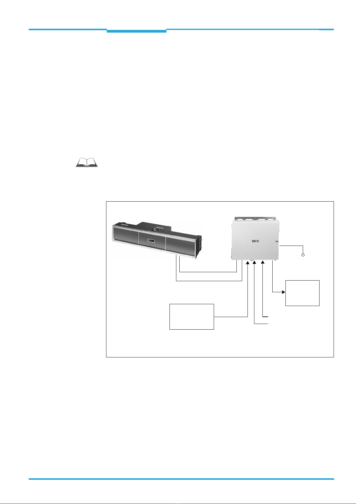
External sensors are required for the reading pulse, detection of the object distance and for
creation of the increment signal. These sensors and the superordinate host processor are
connected to the MSC800.
Fig. 3-1: ICR880/890 Camera System in combination with the MSC800 (single-side reading)
MSC800
Power supply
Mains connection
ICR880/890 System
CAN bus
HOST
Reading pulse
Conveyor speed
MLG Light Grid/
VMS4xx/5xx
Object distance/
Object geometry
Chapter 3Operating Instructions
ICR880/890 Camera Systems
18 ©SICK AG · Germany · All rights reserved · Subject to change without notice 8011325/XL85/2013-08-20
Product description
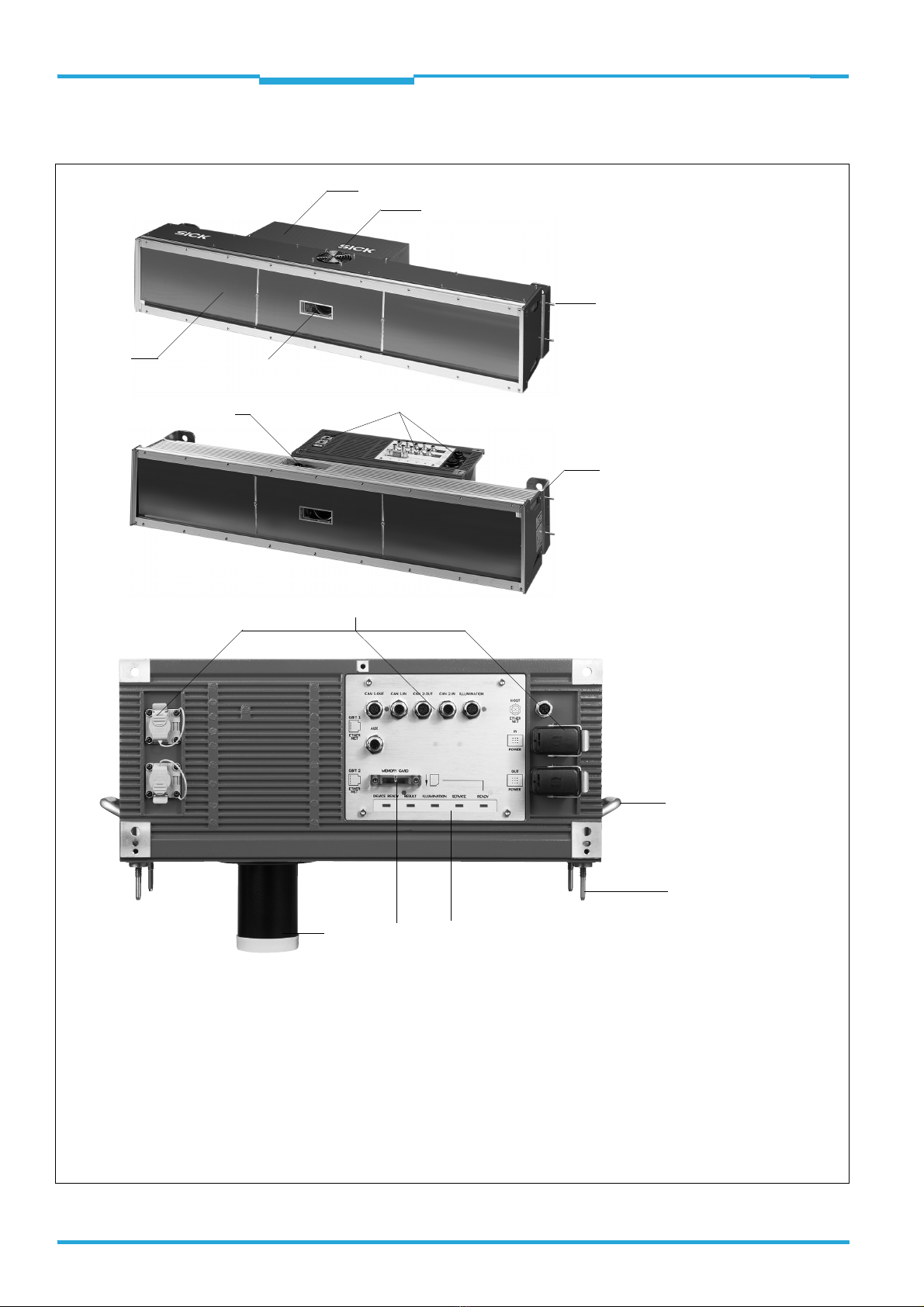
3.1.1 Device view
Fig. 3-2: View of the ICD880/890 Camera and the ICI890 Illumination
2
3
4
6
7
Legend:
1ICI890 Illumination
2ICD880/890 Camera
3Air inlet opening for cooling
the ICI890 Illumination
4Guide pins (4 x) for use in
180° bracket
5ICD880/890 Camera reading
window
6Electrical connections for the
ICI890 Illumination
7Electrical connections for the
ICD880/890 Camera
8Fixing for bracket (2 x)
9
8
bl
Complete Camera System,
from above
Complete Camera System,
from below
(picture differ from actual product)
ICD880/890 Camera,
from below
1
7
bmbnbo
9Handhold for camera (2 x)
bl Threaded centering pin for
fixing to the ICI890 Illumination
bm LEDs for status indicator (5 x)
bn SD memory card for parameter cloning
bo Lens protection tube
5

Operating Instructions Chapter 3
ICR880/890
Product description
8011325/XL85/2013-08-20 ©SICK AG · Germany · All rights reserved · Subject to change without notice 19
3.1.2 Included in delivery
Delivery of the ICR880/890 Camera System includes the following components:
Important For save operation of the SD memory card, use only SICK approved memory card.
An overview of cleaning agents for the front window of the illumination is available in Chap-
ter 10.3, Page 92.
Piece(s) Components Comment
1 Camera with SD memory card ICD880 or ICD890, depending on order
1 ICI890 Illumination Type-depending
1 Deflection mirror (optional) Type-depending
1 MSC800 Type-depending, without connection
cables
1 MLG Light Grid (pre-configured) height dis-
tance detector with connection cable and
installation kit
Application-specific
– or –
1 Object distance detector VMS4xx/5xx with
connection cables and installation kit
4 180° brackets with installation accessories For Camera System and deflection mirror
1 WL18-3 Reading Pulse Sensor (pulse photo-
electric reflex switch) with connection cable
and installation kit
Triggering the reading procedure
1 Connection cable For the power supply of the Camera Sys-
tem
1 Connection cable For the power supply of the ICI890 Illumi-
nation via the camera
1 Connection cable For control of the ICI890 Illumination via
the camera
1 CAN bus data link For networking the Camera System with
MSC800 via the CAN bus
1 Terminal resistance For CAN bus termination at the Camera
System
1 Incremental encoder, resolution
10 mm (394 mil)/pulse
Optional (application-specific)
– or –
1 Incremental encoder, resolution
0.2 mm (7.9 mil)/pulse (using VMS4xx/5xx)
Installation frames Optional (application-specific)
1 Notes on Device with electrical connection
diagram as primary information
Included in the device packaging of the
Camera System
Tab. 3-1: Included in the delivery of the ICR880/890 Camera System

Chapter 3Operating Instructions
ICR880/890 Camera Systems
20 ©SICK AG · Germany · All rights reserved · Subject to change without notice 8011325/XL85/2013-08-20
Product description
3.1.3 Device versions
The camera and the ICI890 Illumination are available in the following versions:
s
In combination of the components result in the following Camera Systems:
Type Part no. Description
Camera with lens
ICD880-3112100 1061170 Max. 19 kHz, lens: focal distance 80 mm (3.15 in),
reading distance 0.75 m to 1.4 m (2.46 ft o 4.59 ft)
ICD890-3200100 1061166 Max. 19 kHz, lens: focal distance 135 mm (5.32 in),
reading distance 1.4 m to 3.0 m (4.59 ft to 9.84 ft)
ICD890-3201100 1061167 Max. 19 kHz, lens: focal distance 135 mm (5.32 in),
reading distance 1.6 m to 3.3 m (5.24ft to 10.82 ft)
ICD890-3300100 1061168 Max. 30 kHz, lens: focal distance 135 mm (5.32 in),
reading distance 1.4 m to 3.0 m (4.59 ft to 9.84 ft)
ICD890-3301100 1061169 Max. 30 kHz, lens: focal distance 135 mm (5.32 in),
reading distance 1.6 m to 3.3 m (5.24 ft to 10.82 ft)
LED Illumination
ICI890-00000 1028219 Red, profile length 1,100 mm (43.3 in), for focal distance 135 mm
(5.32 in)
ICI890-01000 1046888 Red, profile length 900 mm (35.4 in), for focal distance 135 mm
(5.32 in)
ICI890-01100 1051413 Red, profile length 900 mm (35.4 in), for focal distance 80 mm
(3.15 in)
ICI890-02100 1048455 Red, profile length 750 mm (29.5 in), for focal distance 80 mm
(3.15 in)
ICI890-10000 1054855 Blue and white, profile length 1,100 mm (43.3 in), for focal dis-
tance 135 mm (5.32 in)
ICI890-11000 1054856 Blue and white, profile length 900 mm (35.4 in), for focal distance
135 mm (5.32 in)
ICI890-11100 1054857 Blue and white, profile length 900 mm (35.4 in), for focal distance
80 mm (3.15 in)
ICI890-12100 1054858 Blue and white, profile length 750 mm (29.5 in), for focal distance
80 mm (3.15 in)
Tab. 3-2: System component versions
Property System 1 System 2 System 3
System width 770 mm (30.34 in) 950 mm (37.43 in) 1,150 mm (45.31 in)
Max. reading distance 1,400 mm (55.2 in) 2,500 mm (98.5 in) 3,300 mm (130 in)
Depth of field 550 mm (21.6 in) 1,100 mm (43.3 in) 1,700 mm (66.98 in)
Typical track width cover 600 mm (23.6 in) 800 mm (31.5 in) 1,300 mm (51.22 in)
Typical image resolution 200 dpi to 270 dpi 200 dpi to 250 dpi 150 dpi to 200 dpi
Image lift Tracking, analysis,
VCS
Tracking, analysis,
OCR, VCS
Tracking, analysis,
OCR, VCS
Tab. 3-3: Camera Systems versions
Other manuals for ICR880 Generation 3
1
This manual suits for next models
1
Other SICK Digital Camera manuals

SICK
SICK picoCam2 User manual

SICK
SICK midiCam2 User manual

SICK
SICK InspectorP63 Flex C-mount Series User manual

SICK
SICK IVC-2D User manual

SICK
SICK ICD880 Series Manual

SICK
SICK Ranger E40 User manual

SICK
SICK V300 User manual

SICK
SICK EventCam EVC625-CCOXAL5L User manual

SICK
SICK ICR880 Generation 3 User manual

SICK
SICK InspectorP63 Flex C-mount Series User manual


