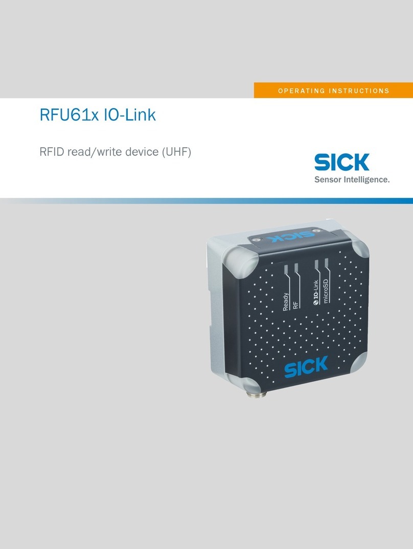
SICK RFU6 Series Manual

Technical information
SICK
RFU6xx function block
SICK RFU6xx PROFIBUS / PROFINET
function block for Mitsubishi iQ PLCs
(GX Works2)

Technical information
RFU6xx FB for
GX Works 2 (PNDP)
Page 2
Version history
Version
Date
Description
V1.0
29.09.2017
Initial version
Table of contents
1 About this document........................................................................................................ 3
1.1 Function of this document............................................................................................ 3
1.2 Target group................................................................................................................ 3
2 General information ......................................................................................................... 4
2.1 Supported PLC controls............................................................................................... 4
2.2 PROFINET / PROFIBUS configuration ........................................................................ 4
3 Module description........................................................................................................... 5
3.1 Block specifications...................................................................................................... 5
3.2 Method of function ....................................................................................................... 6
3.3 Timing.......................................................................................................................... 7
3.4 Behavior in the case of an error................................................................................... 7
3.5 Value transfer .............................................................................................................. 8
3.5.1 Mode..................................................................................................................... 9
3.5.2 Single-Tag mode: SOPAS object trigger control...................................................11
3.5.3 Single-Tag mode: SOPAS output format..............................................................11
3.5.4 Read tag...............................................................................................................13
3.5.5 Write tag...............................................................................................................15
3.5.6 Reading result......................................................................................................17
4 Parameter.........................................................................................................................18
5 Error codes......................................................................................................................20
6 Examples .........................................................................................................................24
6.1 Read tag.....................................................................................................................28
6.2 Write tag.....................................................................................................................30

Technical information
RFU6xx FB for
GX Works 2 (PNDP)
Page 3
1 About this document
Please read this chapter carefully before working with this documentation and the
FB_SICK_RFU6xx_PNDP function block.
1.1 Function of this document
This operating instruction explains how to use the FB_SICK_RFU6xx_PNDP function block.
1.2 Target group
This technical instruction is intended for qualified personnel such as planning engineers, de-
velopers and operators of machines and systems who needs a communication between a
SICK RFU6xx device and a Mitsubishi iQ-Serie PLC via PROFINET / PROFIBUS.

Technical information
RFU6xx FB for
GX Works 2 (PNDP)
Page 4
2 General information
The function block FB_SICK_RFU6xx_PNDP supports data exchange between a SICK
RFU6xx RFID interrogator and a Mitsubishi Q-Series PLC via PROFIBUS or PROFINET.
Functionality of the function block:
- Send a software trigger via the PLC
- Receive telegrams sent by the device which can be configured in the SOPAS
i
output
format (reading results)
- Read and write transponder content (Single-Tag / Multi-Tag mode)
2.1 Supported PLC controls
This function block can be used in combination with iQ-Series PLC which is able to connect a
PROFIBUS or PROFINET device directly or via a gateway module (e.g. QJ71PB92D).
2.2 PROFINET / PROFIBUS configuration
Before starting with the function block, it is necessary to setup the hardware in the I/O con-
figuration. The function block communicates with connected device via process data varia-
bles. These variables contain the cyclic process data of the fieldbus device. The length of the
selected containers indicates the amount of data, which can be exchanged in one fieldbus
cycle.
Please note!
The FB is only compatible with the following process data containers:
- 32 byte input
- 32 byte output
Other modules can be plugged (e.g. parameter modules or Control In/Out
modules) and have no influence on the functionality of the FB.
If a telegram is longer than the projected module, the data will be transmitted fragmented
over several PLC cycles. The data flow is managed via a handshake mechanism by the func-
tion block.
Please use a free address for the data mapping with a global variable.
Figure 1: Example PROFIBUS configuration
Figure 2: Global label settings
i
SOPAS is an engineering tool used for configuring SICK sensors.

Technical information
RFU6xx FB for
GX Works 2 (PNDP)
Page 5
3 Module description
The FB_SICK_RFU6xx_PNDP function block simplifies the usage of a SICK RFU6xx RFID
interrogator on Mitsubishi iQ-Series PLCs.
The function block is working asynchronously, which means the processing is done via vari-
ous function block call ups. Therefore it is necessary that the function block is called cyclical-
ly in the user program.
The RFU library can only be used in combination with the SICK_AutoIdentBase_PNDP li-
brary. This library contains the FB_SICK_CCOM_PNDP, which facilitates the communication
between the PLC and the device. The F_SICK_GetValue/F_SICK_SetValue functions are
used internally to serialize and de-serialize device telegrams.
3.1 Block specifications
Block name: FB_SICK_RFU6xx_PNDP
Version: 1.0
Used libraries: SICK_AutoIdentBase_PNDP
Used structures: ST_SICK_RFU6xx
Uses special registers: -
Block call: Cyclic
Block language: ST (Structured text)
Developed under: GX Works2 V1.536J
The following figure shows how the function block is represented in the function block dia-
gram (FBD) view.
Figure 3: Represenation of the function block in FBD

Technical information
RFU6xx FB for
GX Works 2 (PNDP)
Page 6
3.2 Method of function
The following parameters must be specified before the FB_SICK_RFU6xx_PNDP function
block can be used.
InputData: Data link to the 16 Word (32Byte) input module of the fieldbus device
OutputData: Data link to the 16 Word (32Byte) output module of the fieldbus device
TOut: Timeout (e.g. T#5s). The process will be interrupted if this time is
elapsed without obtaining a valid device response.
Data: The function block requires a variable from the data type
ST_SICK_RFU6xx. This data type describes input and output parame-
ters for the individual block functions. Please create a variable and link it
to the “Data” input of the function block.
To carry out a function (TriggerOn, ReadTag etc.), the desired function bit must be selected
first. Only one function can be carried out at the same time. The “Req”parameter must be
triggered with a rising edge (signal change from logic zero to one) in order to carry out the
selected function. As long as no valid response has been received, the “ReqBusy”parameter
is used to signal this.
The output parameter “ReqDone” indicates that the function has been successfully complet-
ed. If data was requested from the device during this function (e.g. ReadTag), this data is
copied to the linked data structure (Data).
Data sent via trigger command (TriggerOn, TriggerOff) or directly by the device (e.g. direct
trigger via a photoelectric sensor) is stored in the data structure “ReadResult_Result”. The
“RdDone” output parameter indicates for one PLC cycle that new data has been received.
The data sent by the device can be changed or adapted in SOPAS output format.

Technical information
RFU6xx FB for
GX Works 2 (PNDP)
Page 7
3.3 Timing
Figure 4: Timing diagram
1: The selected function (in this case “TriggerOn”) is executed if the “Req” input is triggered
by a rising edge. The “TriggerOn” bit must be selected at the same time/in advance. Only
one function can be executed at the same time, otherwise an error will terminate the se-
quence.
2: The “ReqDone” flag indicates that the sequence has been successfully completed. If an
error occurred, the sequence is terminated with “Error”. The parameter “Errorcode” contains
the error code.
3.4 Behavior in the case of an error
If the function module has an incorrect input value or faulty input circuit, an error bit (Error) is
set and an error code (Errorcode) is output. In this case, no further processing is carried out.
The parameters (Error, Errorcode) of the function module retain their value until a new com-
mand is started.

Technical information
RFU6xx FB for
GX Works 2 (PNDP)
Page 8
3.5 Value transfer
The “Data” parameter of the function block contains all input and output parameters for the
supported block functions. The data structure has a fixed definition and may not be modified.
Figure 5: ST_SICK_RFU6xx PLC data type

Technical information
RFU6xx FB for
GX Works 2 (PNDP)
Page 9
3.5.1 Mode
The RFU can only communicate with a single transponder at the same time. For this reason,
read and write commands are always addressed. The function block uses the transponder
UII (Unique Item Identifier) in order to identify the transponder.
The function block supports two different modes in order to determine which transponder UII
is to be communicated with:
Single-Tag mode:
The system always communicates with the transponder which is currently in the reading
field. This mode can only be used when precisely one tag is located in the reading field. A
special configuration of the RFU output format with SOPAS (see chapter 3.5.3) is required
for this mode. If the Single-Tag mode is active, a trigger is automatically activated to read the
UII and the antenna with the best signal strength (RSSI).
Multi-Tag mode:
A user defined transponder UII is used for purposes of communication. The antenna to be
used must be defined in the respective read/write parameters.
Parameter
Declara-
tion
Data type
Description
Mode
Input
Bit
Addressing mode.
FALSE: Single-Tag mode active
TRUE: Multi-Tag mode active
Mode_
UIILength
Input /
Output
Word
[Signed]
Word length of the UII.
0 = Unaddressed
1...16 = Word length of the UII defined in
the Mode_UII array.

Technical information
RFU6xx FB for
GX Works 2 (PNDP)
Page 10
Parameter
Declara-
tion
Data type
Description
Mode_UII
Input /
Output
Word
[Signed]
(0..15)
Transponder Identification (UII) in a hexa-
decimal format.
The length of the UII must be defined by the
Mode_UIILength parameter.
The UII is automatically determined in
the Single-Tag mode and does not have
to be assigned.
Example:
UII (hex)= 1234 0000 0000 0000 0000 0002
Mode_RSSI
Output
Word
[Signed]
(0..3)
Outputs the RSSI values (reception
strength) of the transponder in the reading
field (only in Mode 1).
[1] = RSSI value from antenna 1 (internal)
[2] = RSSI value from antenna 2 (external)
[3] = RSSI value from antenna 3 (external)
[4] = RSSI value from antenna 4 (external)
Table 1: Mode parameters

Technical information
RFU6xx FB for
GX Works 2 (PNDP)
Page 11
3.5.2 Single-Tag mode: SOPAS object trigger control
The object trigger control settings define the status of reading gate (open / closed). The de-
vice sends a reading result to the PLC after each reading gate. The function block uses this
mechanism in order to read the UII, the PC-Word and RSSI values of the corresponding
transponder.
The SOPAS settings under menu item Parameter
Reading configuration
Object trigger
control must be defined, that the trigger window is opened via a "Command" and closed
when a "Good Read" result is received or after a defined period of time (e.g. 1000ms).
Figure 6: Object Trigger settings (SOPAS)
3.5.3 Single-Tag mode: SOPAS output format
The output format defines the content of the telegram that is sent by the device as soon as
the trigger window is closed. This telegram is evaluated by the PLC. Afterwards the function
block used the information to create addressed read / write commands. The SOPAS output
format must be structured as shown in Figure 7 in order to use the function block with the
Single-Tag mode.
Figure 7: Output format configuration (SOPAS)

Technical information
RFU6xx FB for
GX Works 2 (PNDP)
Page 12
Please ensure that the format of the blocks "RSAVG1...4" are set to hexadecimal format
(double-click the respective block). The "PCUII" block may not be changed.
Figure 8: Settings for RSSI blocks (RSAVG1...4)
Depending on the number of tags located in the receiving range of the RFU and the config-
ured RSSI threshold, the following ASCII telegrams are sent by the device:
Case 1: (Only one tag in the field):
[STX]01;[RSSI Antenna 1] [RSSI Antenna 2] [RSSI Antenna 3] [RSSI Antenna 4]
[PC+UII][ETX]
Case 2: (More than one tags in the field):
[STX]0X[ETX]
Case 3: (No tag in the field):
[STX]00[ETX]

Technical information
RFU6xx FB for
GX Works 2 (PNDP)
Page 13
3.5.4 Read tag
The “Read Tag”function is used to read a defined data area of the tag. The selected mode
determines which transponder should be used by the system (see chapter 3.5.1).
The following parameters must be defined before you can start a read request:
Parameter
Declaration
Data
type
Description
ReadTag_
Bank
Input
Word
[Signed]
Selection of the memory bank that should
be used.
0 = Reserved
1 = UII/EPC
2 = TID
3 = User memory
ReadTag_
StartWord
Input
Word
[Signed]
First word (16Bit) that should be read.
ReadTag_
WordCount
Input
Word
[Signed]
Number of words (16Bit) that should be
read.
Valid value range:
[1..32]
ReadTag_
Retry
Input
Word
[Signed]
Number of read attempts to be carried out.
Valid value range:
Lo Nibble (retries on one channel) 16#[0..7]
Hi Nibble (retries on different channels)
16#[0..5]
Example:
Retry = 16#0032 executes 3 changes of the
channel (4 channels) with 2 retries per
channel in each case (3 repetitions), i.e. a
total of 4x3= 12 attempts.

Technical information
RFU6xx FB for
GX Works 2 (PNDP)
Page 14
Parameter
Declaration
Data
type
Description
ReadTag_
Antenna
Input /
Output
Word
[Signed]
Antenna selection for the current read re-
quest. Only one antenna can be selected
per request.
A1 = Antenna 1 (internal/external, depend-
ing on device type)
A2 = Antenna 2 (external)
A3 = Antenna 3 (external)
A4 = Antenna 4 (external)
Value
A4
A3
A2
A1
1
X
2
X
4
X
8
X
In the Single-Tag mode, the antenna is
selected automatically (antenna with the
best signal strength).
Valid value range:
[1…15]
ReadTag_
DataLength
Output
Word
[Signed]
Valid length of read content in words
(16Bit). Required in order to define which
content of the array "ReadTag_Data" is
valid.
ReadTag_
Data
Output
Word
[Signed]
(0..31)
Tag content.
Table 2: Read tag parameters
Please note!
If you want to read out more than 32Words (64Byte) tag data, please execute
this function several times with different offsets (ReadTag_StartWord).

Technical information
RFU6xx FB for
GX Works 2 (PNDP)
Page 15
3.5.5 Write tag
The "Write Tag" function is used to write values to a defined data area of the tag. The select-
ed mode determines which transponder should be used by the system (see chapter 3.5.1).
The following parameters must be defined before you can start a write request:
Parameter
Declaration
Data type
Description
WriteTag_
Bank
Input
Word
[Signed]
Selection of the memory bank that should
be written.
0 = Reserved
1 = UII/EPC
2 = TID (Read only)
3 = User memory
WriteTag_
StartWord
Input
Word
[Signed]
First word (16Bit) that should be written.
WriteTag_
WordCount
Input
Word
[Signed]
Number of words (16Bit) that should be
written.
Valid value range:
[1..32]
WriteTag_
Retry
Input
Word
[Signed]
Number of write attempts to be carried out.
Valid value range:
Lo Nibble (retries on one channel) 16#[0..7]
Hi Nibble (retries on different channels)
16#[0..5]
Example:
Retry = 16#32 executes 3 changes of the
channel (4 channels) with 2 retries per
channel in each case (3 repetitions), i.e. a
total of 4x3= 12 attempts.

Technical information
RFU6xx FB for
GX Works 2 (PNDP)
Page 16
Parameter
Declaration
Data type
Description
WriteTag_
Antenna
Input/Output
Word
[Signed]
Antenna selection for the current write re-
quest. Only one antenna can be selected
per request.
A1 = Antenna 1 (internal/external, depend-
ing on device type)
A2 = Antenna 2 (external)
A3 = Antenna 3 (external)
A4 = Antenna 4 (external)
Value
A4
A3
A2
A1
1
X
2
X
4
X
8
X
In the Single-Tag mode, the antenna is
selected automatically (antenna with the
best signal strength).
Valid value range:
[1…15]
WriteTag_
Data
Input
Word
[Signed]
(0..31)
Data that should be written to the selected
tag area. The length must be defined by the
WriteTag_WordCount parameter.
Table 3: Write tag parameters
Please note!
If you want to write more than 32Words (64Byte) tag data, please execute this
function several times with different offsets (WriteTag_StartWord).

Technical information
RFU6xx FB for
GX Works 2 (PNDP)
Page 17
3.5.6 Reading result
The "ReadResult_Result" array stores data that is sent via a trigger command (TriggerOn,
TriggerOff) or directly from the device (e.g. direct trigger via photoelectric sensor). The output
parameter “RdDone”indicates that new data arrived for one PLC cycle.
Parameter
Declaration
Data type
Description
ReadResult_
Counter
Output
Word
[Signed]
This counter is incremented when a
new telegram is arrived.
Value range:
[0..32767]
ReadResult_
Length
Output
Word
[Signed]
Byte length of received reading result.
ReadResult_
Result
Output
Word
[Signed]
(0..99)
Received data (can be defined in
SOPAS).
The maximum length of the received
data is 200Bytes (100Words).
Table 4: Reading result parameters

Technical information
RFU6xx FB for
GX Works 2 (PNDP)
Page 18
4 Parameter
Parameter
Decla-
ration
Data type
Description
InputData
Input
Word[Signed]
(0..15)
Data link to the 16 Word (32Byte) input module
of the fieldbus device.
OutputData
Output
Word[Signed]
(0..15)
Data link to the 16 Word (32Byte) output mod-
ule of the fieldbus device.
TOut
Input
Time
Time, after which a timeout error will be set
(e.g. T#5s).
Req
Input
Bit
Rising edge: Start the selected block function.
TriggerOn
Input
Bit
Block function: Open a reading gate
This function requires the following SOPAS
setting:
Object Trigger ControlStart by “Command”
The result sent from the device (defined in the
SOPAS output format) is stored in the
"ReadResult_Result" array.
TriggerOff
Input
Bit
Block function: Close a reading gate.
This function requires the following SOPAS
setting:
Object Trigger ControlStop by “Command”
The result sent from the device (defined in the
SOPAS output format) is stored in the
"ReadResult_Result" array.
ReadTag
Input
Bit
Block function: Read tag data.
Please define the parameters defined in chap-
ter 3.5.4.
WriteTag
Input
Bit
Block function: Write tag data.
Please define the parameters defined in chap-
ter 3.5.5.
Data
Input /
Output
ST_SICK_
RFU6xx
This In- /Output variable needs a link to param-
eter from the data type ST_SICK_RFU6xx.
This data type describes input and output pa-
rameters for the individual block functions.
RdDone
Output
Bit
Rising edge: New reading result received.
The reading result and the valid length are
stored in the variable "ReadResult_Length” /
“ReadResult_Result".
ReqDone
Output
Bit
Indicates whether a request has been success-
fully completed.
TRUE: Successfully completed
FALSE: Not completed

Technical information
RFU6xx FB for
GX Works 2 (PNDP)
Page 19
Parameter
Decla-
ration
Data type
Description
ReqBusy
Output
Bit
Request in progress.
Error
Output
Bit
Error flag.
FALSE: No error
TRUE: Error occurred
Errorcode
Output
Word[Signed]
(0..1)
Error status (see Error codes)
Table 5: Function block parameter list

Technical information
RFU6xx FB for
GX Works 2 (PNDP)
Page 20
5 Error codes
The “Errorcode”parameter contains the following error information:
- Errors of the FB_SICK_RFU6xx_PNDP function block
- Errors of the FB_SICK_CCOM_PNDP function block
- Errors of the F_SICK_GetValue / F_SICK_SetValue functions
- Errors sent by the device
Error code
Brief description
Description
[0] = 16#0000
[1] = 16#0000
No error
No error
[0] = 16#0001
[1] = 16#0000
Time out detected
(FB_SICK_CCOM_PNDP)
The command could not be executed within
the defined timeout period.
Possible causes:
- Device is not connected to the PLC
- Device is not sending command re-
sponses (echo)
- Processing time of the command >
timeout period
[0] = 16#0002
[1] = 16#0000
Reserved
(FB_SICK_CCOM_PNDP)
Reserved
[0] = 16#0003
[1] = 16#0000
Reserved
(FB_SICK_CCOM_PNDP)
Reserved
[0] = 16#0004
[1] = 16#0000
Reserved
(FB_SICK_CCOM_PNDP)
Reserved
[0] = 16#0005
[1] = 16#0000
Reserved
(FB_SICK_CCOM_PNDP)
Reserved
[0] = 16#0006
[1] = 16#0000
Received telegram
> Record size
(FB_SICK_CCOM_PNDP)
The received command response does not
completely fit into the record array.
[0] = 16#0007
[1] = 16#0000
Invalid input parameter
(CommandLength)
(FB_SICK_CCOM_PNDP)
The command length value is less or equal
than 0.
[0] = 16#0008
[1] = 16#0000
Invalid input parameter
(CommandLength)
(FB_SICK_CCOM_PNDP)
The command length value is greater than
the size of the command array.
[0] = 16#0009
[1] = 16#0000
Fragmentation error
(FB_SICK_CCOM_PNDP)
Data fragmentation error occurred.
[0] = 16#000A
-
16#000F
[1] = 16#0000
Reserved
(FB_SICK_CCOM_PNDP)
Reserved
[0] = 16#0010
[1] = 16#0000
Time out detected
The command could not be executed within
the defined timeout period.
Possible causes:
- Device is not connected to the PLC
- Device is not sending command re-
sponses (echo)
- Processing time of the command >
timeout period
Table of contents
Other SICK RFID System manuals
Popular RFID System manuals by other brands
Siemens
Siemens SIMATIC RF1000 Series Configuration manual
Solo
Solo 5010V1 user manual
HID
HID Technology solutions 1101 user guide

Rockwell Automation
Rockwell Automation Allen-Bradley 58UHF user manual
Feig Electronic
Feig Electronic OBID i-scan ID ISC.LRM2500-A installation manual
IFM
IFM DTM424 operating instructions
Panasonic
Panasonic FZ-VFP401 Series operating instructions
Datalogic
Datalogic DLR-BT001 Series Quick reference guide

HID
HID iCLASS SE U90 Series installation guide

IFM
IFM ANT600 installation instructions
Feig Electronic
Feig Electronic ID LRU500i-BD Series Installation
Dormakaba
Dormakaba Quantum II RFID ECU installation instructions
