Siding Tools Industries UK-12 User manual

Trancheuse pour
revêtement mural
de 12
"
MANUEL D’UTILISATION
12" Siding shear
OWNER’S MANUAL
AVERTISSEMENT
Lire et Comprendre toutes les
directives. Le non-respect des directives
décrites ci-dessous peut causer des
blessures graves.
VEUILLEZ CONCERVER CES
DIRECTIVES POUR REFERENCE
ULTERIEURE.
WARNIG
Read and understand all
instructions. Failure to follow all
instructions listed below may
result in serious bodily injury.
SAVE THESE
INTRUCTIONS FOR
FUTURE REFERENCE
UK-12

-1-
SAFETY RULES FOR THE 12" SIDING SHEAR
1. READ AND UNDERSTAND THIS INSTRUCTION MANUALBEFORE
OPERATINGTHE12"WALL COVERING CUTTER.
2. The 12’’ Siding Shear comes with a 1 year warranty. To activate your
warranty, we invite you to register on our website in the service tab at :
sidingtoolsindustries.com
3.
If you are not thoroughly familiar with the operation of the 12" Wall
Covering Cutter,obtainadvicefromaqualifiedworkerorcall450-527-
7840
4.
Stay alert. Do not operate while under the influence of drugs, alcohol, or
medication.
5.
Alwayswearsafety approvedeye protectionwith sideshields(ANSIZ87.1)
6.
Keepwork areaandfree of debris.
7.
Keepchildren andunauthorized persons away from the 12" WallCovering
Cutter and workarea.
8.
Make sure tool is secure. Operate only on a firm substrate or solid stand.
9.
Use the right tool. Do not force the 12" Wall Covering Cutter or use it for a
job for which it was not designed; use only on approved materials.
10.
Keep blade sharp. A dull blade will not perform properly.
11.
Always keep hands away from blade while operating or carrying.
12.
Do not alter or misuse this tool. The 12" Wall Covering Cutter is
precision built; modifications not specified in this manual may result in
a dangerous condition.
13.
Maintain the 12" Wall Covering Cutter with care. Keepblade sharpand
clean. Follow instructions for lubricating and changing accessories.
14.
Useonlyrecommendedaccessories.Theuseofimproperaccessoriesmay
causehazardsorinjury.
15.
Never leave the 12"Wall Covering Cutter unattended. Secure the handle
with the safety lock when not in use.
WARNING: FAILURE TO FOLLOW THESE RULES MAY RESULT IN SERIOUS
INJURY! USING THIS MACHINE WITH RESPECT AND CAUTION WILL
CONSIDERABLY LESSEN THE POSIBILITY OF PERSONAL INJURY.
SET UP
-2-
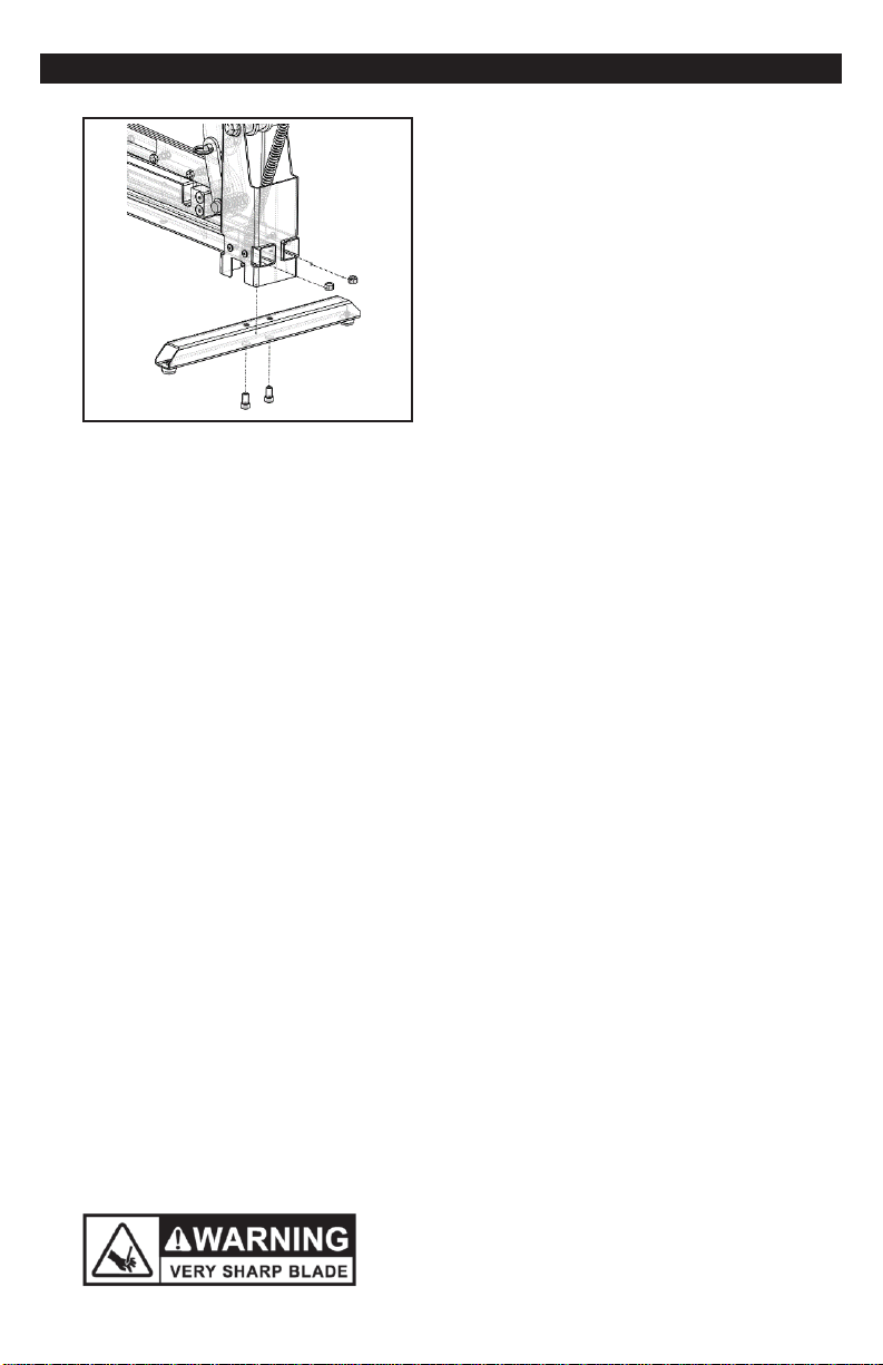
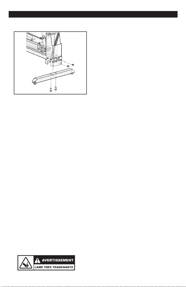
Installation of the Cutter
Install
the front cross bar to the cutter base
with the two bolts and nuts
provided, as
shown.
Warning:
Do not put your fingers
against the sharp edge of the blade
at any time.
CUTTING
-3-
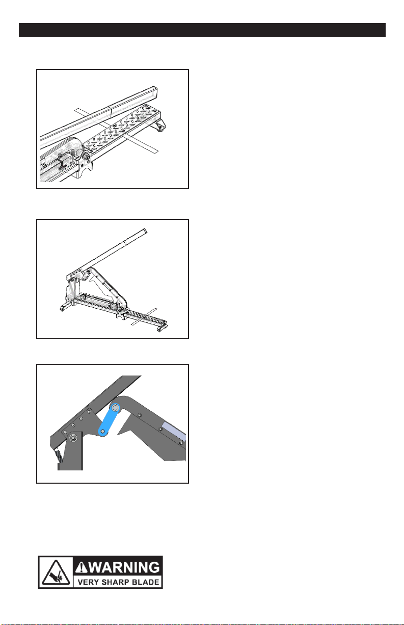
Cutting Preparation
Detach the safety clip from the
handle.
Warning:
Do not put your fingers
against the sharp edge of the
blade at any time.
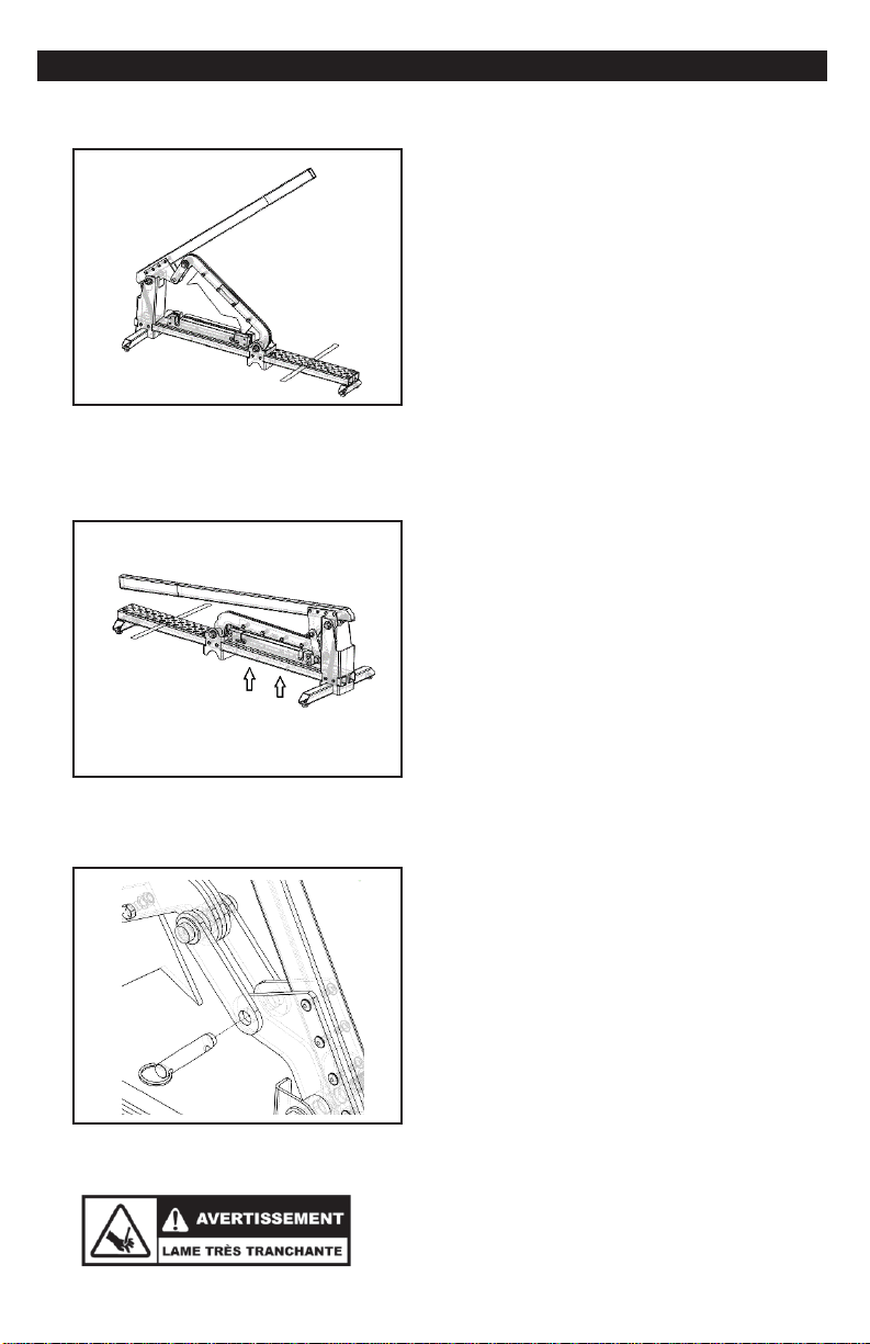
Cutting Preparation
Secure the blade to lock the
mechanism.
Lift the handle and position the
blade in the locked position
Warning:
Do not put your
fingers against the sharp edge
of the blade at any time.
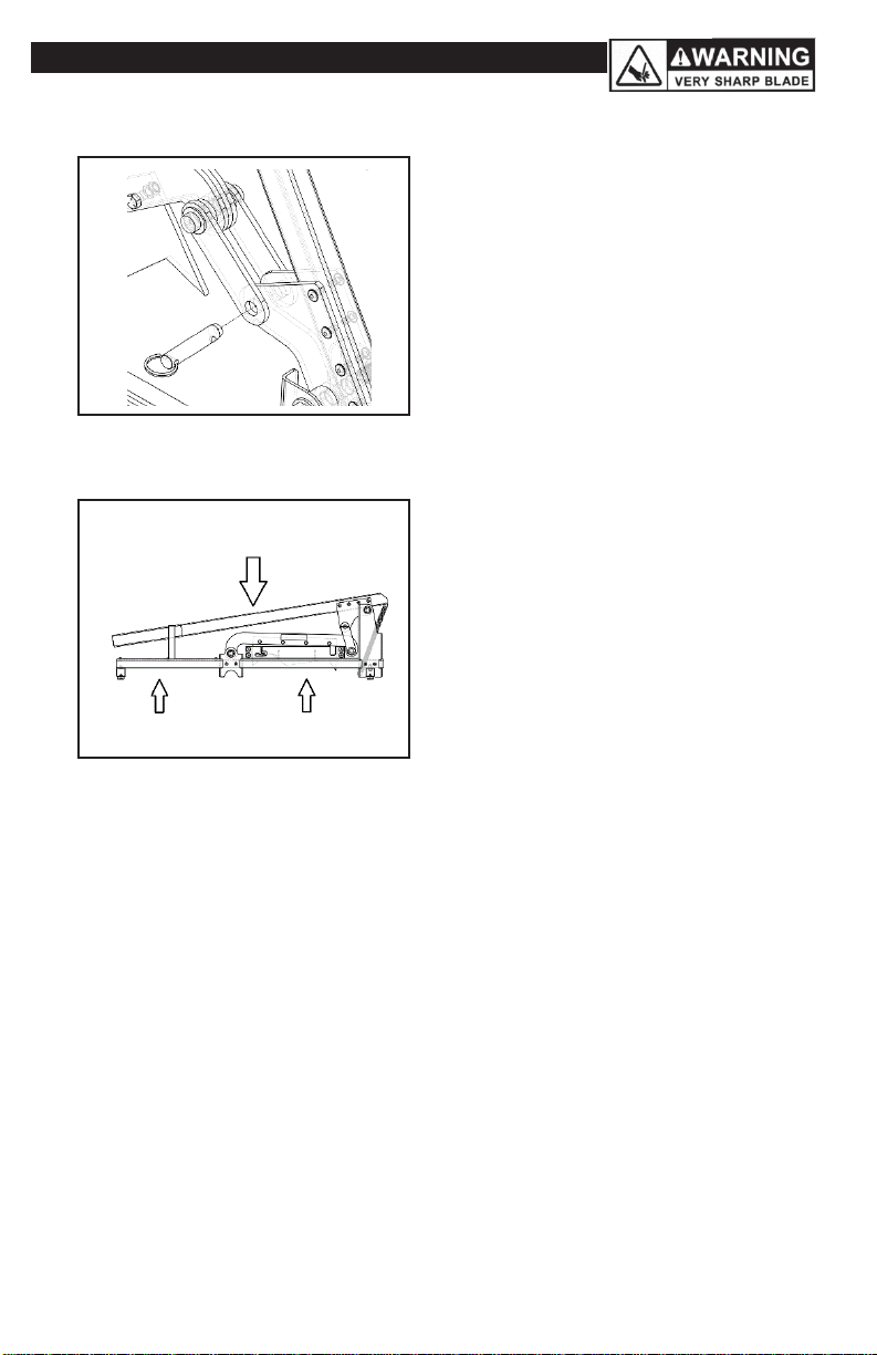
Cutting Preparation
The mechanism is locked when the
pivot is raised upwards as shown in
the picture. To do this, raise the
handle to its highest and manipulate
the pivot manually
Warning:
Do not put your
fingers against the sharp edge
of the blade at any time.
CUTTING
-4-
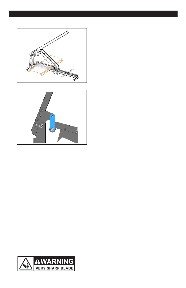
Cutting Preparation
Slide the profile into the
predefined block for the type of
profile to be cut. Put the blade in
the cutting position by raising the
handle very high to unlock the
mechanism, then down the handle
to cut.
Warning:
Do not put your
fingers against the sharp edge
of the blade at any time.
Cutting Preparation
Before cutting, reposition the pivot
downwards in the working
position. To do this, raise the
handle to its highest and
manipulate the pivot manually.
Warning:
Do not put your
fingers against the sharp edge
of the blade at any time.

-5-
MAINTENANCE
Maintenance
For any service, it is recommended to
contact Siding Tools Industries at 450-
527-7840
Warning:
It is recommended to
lubricate the blade on a regular
period of time with PL-100 or
equivalent. Do not use WD-40.
Block change according to the material
to cut
Keep the slicer closed. Remove the 4
screws from the bottom of the base.
Warning:
Do not put your fingers
against the sharp edge of the
blade at any time.
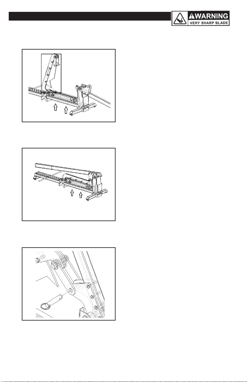
Block change according to the material
to cut
Disengage the pivot pin. Raise the handle
and the blade to clear the block
completely.
Warning:
Do not put your fingers
against the sharp edge of the
blade at any time.
-6-
MAINTENACE
Block change according to the material
to be cut
Clear the block completely. Hold
or attach the blade holder to
secure it in the raised position.
Remove the blocks. Position
another block according to the
material to cut. Screw the 4
screws lightly.
Warning:
Do not put your fingers
against the sharp edge of the
blade at any time.
Block change according to the material
to be cut
Lower the blade to the cutting
position to validate the alignment
of the block. Tighten the 4 block
fixing screws.
Warning:
Do not put your fingers
against the sharp edge of the
blade at any time.
Block change according to the material
to be cut
Re-engage the pivot pin.
Warning:
Perform a cut test
before proceeding to validate the
alignment of the blade with the
block.

-7-
MAINTENACE
Blade lade change
Disengage the pivot pin. Raise the handle
and the blade to clear the block
completely.
Warning:
Do not put your fingers
against the sharp edge of the
blade at any time.
Blade change
Clear the block completely.
Remove the 4 bolts to remove the
blade. Position the new blade and
slightly refit the 4 bolts.
Warning:
Do not put your fingers
against the sharp edge of the
blade at any time
Blade change
Lower the blade to the cutting
position to confirm the alignment
of the blade. Tighten the 4 bolts.
Warning:
Do not put your fingers
against the sharp edge of the
blade at any time
-8-
MAINTENACE
Block change according to the material
to be cut
Re-engage the pivot pin.
Warning:
Perform a cut test
before proceeding to validate the
alignment of the blade with the
block.
Transport
Attach the safety clip to the
handle. If the tie is in good
condition, you can lift the shear by
the handle. If not, it is advisable to
raise with two hands by the base.
The weight of the shears is about
55lbs.
Warning:
Secure the safety clip.
For transport by lifting the base,
pay attention to the tip of the
blade protruding at the front.
-9-
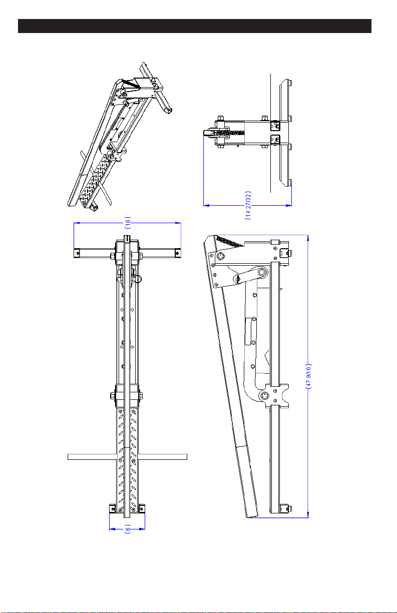
OVERAL DIMENSION

PART LIST
-10-

PART LIST
No. article
Part name
Quantity
1
Quick release pin
1
2
Hook and loop cable tie
1
3
Push ring cap
4
4
Round bumpers with threaded stud
4
5
Extension spring with hook end
1
6
Rubber handle
1
7
1/4'' Rivet
24
8
5/8''-11 UNC Hexagonal locknuts
2
9
5/8'' Flat washer
4
10
5/8''-11 UNC Hexagonal head screw
2
11
#10-24 UNC Lock nut
4
12
3/8''-16 UNC Hexagonal head screw
4
13
3/8''-16 UNC Hexagonal locknuts
6
14
3/8''-16 UNC Socket head screw
2
15
UKUT12-00008-R01, Joint plate
2
16
UKUT12-00007-R01, Handle
1
17
UKUT12-00002-R01, Brace A
2
18
UKUT12-00017-R01, Brace D
1
-11-

PART LIST
No. article
Part name
Quantity
19
UKUT12-00016-R01, Shaft
2
20
UKUT12-00009-R01, Non-skid plate
1
21
UKUT12-00001-R01, Structural Rails R
1
22
UKUT12-00003-R01, Reference plate
1
23
UKUT12-00005-R01, Lever support
1
24
UKUT12-00006-R01, Spindle support
1
25
UKUT12-00010-R01, Blade support
4
26
UKUT12-00011-R01, Structural Rails L
1
27
UKUT12-00013-R01, 1/4'' Plate
4
28
UKUT12-00014-R01, Long Structural foot
1
29
UKUT12-00018-R01, Brace E
4
30
UKUT12-00004-R01, Brace B
2
31
UKUT12-00012-R01, Short Structural foot
1
32
UKUT12-00015-R01, Brace C
3
33
UKUT12-LAME-R01, Blade
1
-12-

AVERTISSEMENT: LA NON-OBSERVATION DE CES RÈGLES PEUT
ENTRAINER DE GRAVES BLESSURES! L’UTILISATION DE CET APPAREIL AVEC
RESPECT ET PRUDENCE DIMINUERA CONSIDÉRABLEMENT LA POSSIBILITÉ DE
BLESSURES CORPORELLES.
RÈGLES DE SÉCURITÉ POUR LA TRANCHEUSE DE
REVÊTEMENT MURAL 12"
1. LISEZ ET COMPRENEZ BIEN LE MANUEL D’UTILISATION
AVANT D’UTILISER LA TRANCHEUSE POUR REVÊTEMENT
MURAL 12".
2. La trancheuse de revêtement mural 12’’ est muni d’une garantie de 1 ans.
Pour activer votre garantie, nous vous invitons à vous enregistrer sur notre
site internet dans l’onglet service au : sidingtoolsindustries.com
3.
Si vous n’êtes pas complètement familier avec lefonctionnement de la
trancheuse pour revêtement mural 12", demandezconseilàun
travailleurqualifiéouappelezle450-527-7840.
4.
Soyez vigilant. N’utilisez pas l’appareil sous l’effet de drogues,
d’alcool ou
de médicaments.
5.
Porteztoujoursdeslunettesdesécuritéhomologuesavecdes
Œillères
(ANSIZ87.1)
6.
Maintenir votre zone de travail propre et sans débris.
7.
Gardezlesenfantsetlespersonnesnon-autoriséeshorsdeportéede la
trancheuse pour revêtement mural 12" et de lazone detravail.
8.
Assurez-vousquel’outil est sécuritaire. Utilisez-leuniquement sur
une surface dure ou un support ferme.
9.
Utiliser le bon outil. Ne forcez pas la trancheuse de revêtement
mural 12" ou ne l’utilisez pas pour une tâche pour laquelle il n’a
pas été conçu; utilisez uniquement sur des
matériaux approuvés.
10.
Maintenirlalameaiguisée.Unelame émousséenecoupera
pas correctement.
11.
Garder les mains loin de la lame lorsque vous l’utilisez ou la transporter.
12.
Nemodifiez pas oun’utilisez abusivement cet outil. La trancheuse
pour revêtement mural 12" est fabriqué avec précision; les
modifications non spécifiées dans ce manuel d’utilisation peuvent
créer des conditions d’utilisation dangereuses.
13.
Entretenez la trancheuse de revêtement mural 12" avec soin. Maintenez
la lame aiguisée et propre. Respectez les consignes de lubrification et de
changement des accessoires.
14.
Utilisez uniquement les accessoires recommandés. L’utilisation
d’accessoires inappropriés peut créer des dangers ou provoquer
des blessures.
15.
Nelaissezjamaisla trancheuse de revêtement mural 12" sans
surveillance.Verrouillezlapoignéeavec leverrou desécurité
lorsque la trancheuse de revêtement mural 12" n’est pasutilisé.
-13-
MONTAGE
Montage de la Tranche
Fixerla barre transversale avant
àlabaseen utilisant les deux
boulons et écrous fournis,
comme illustré.
Avertissement:
Ne jamais poser
les
doigts sur le bord tranchant de la
lame.
-14-

COUPE
Préparation pour Couper
Détacher l’attache de sécurité du
manche.
Avertissement:
Ne jamais poser les
doigts sur le bord tranchant de la
lame.
Préparation pour Couper
Sécuriser la lame pour bloquer le
mécanisme.
Lever le manche et positionner la lame
en position barrée.
Avertissement:
Ne jamais poser les
doigts sur le bord tranchant de la
lame.
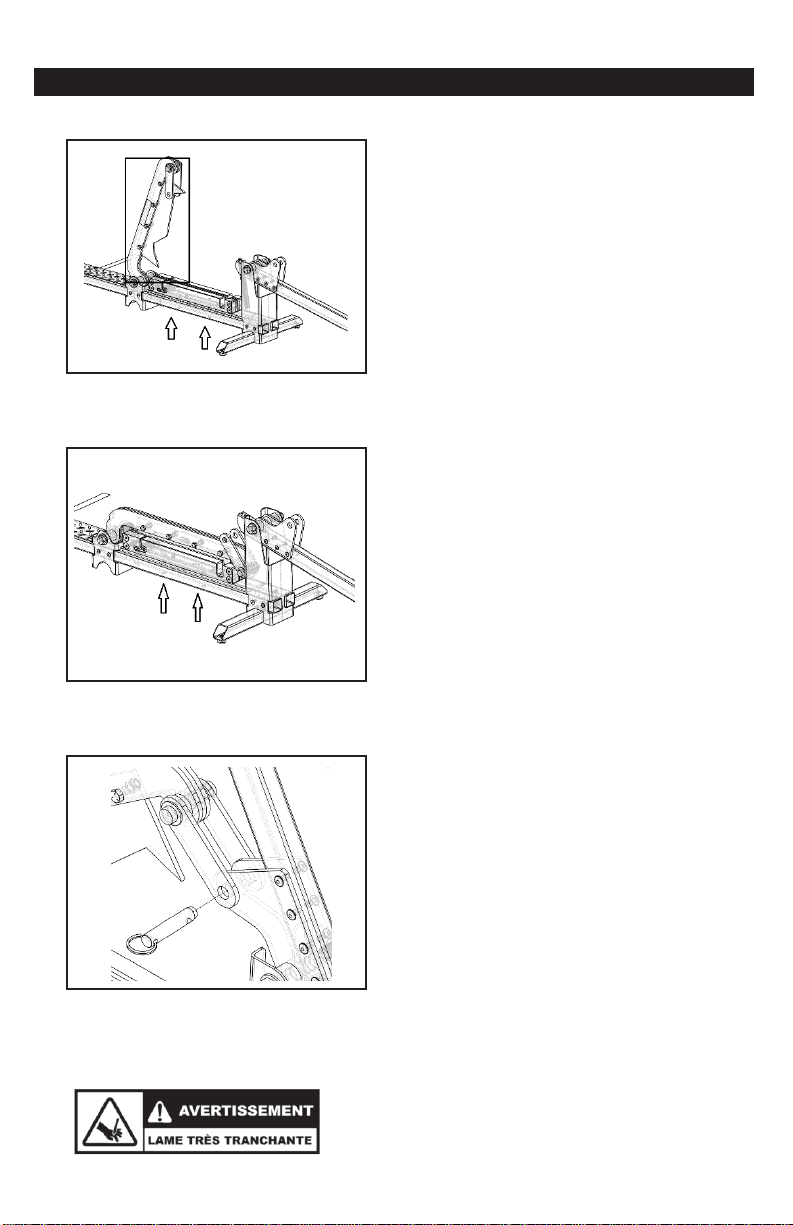
Préparation pour Couper
Le mécanisme est barré lorsque le
pivot est relevé vers le haut comme
montré sur l’image. Pour le faire,
relever le manche à son plus haut
et manipuler le pivot manuellement.
Avertissement:
Ne jamais poser les
doigts sur le bord tranchant de la
lame.
-15-

COUPE
Préparation pour Couper
Glisser le profile dans le bloc
prédéfini pour le type de profilé à
couper. Mettre la lame en position
de coupe en relevant le manche
très haut afin de débloquer le
mécanisme, puis descendre le
manche pour couper.
Avertissement:
Ne jamais poser les
doigts sur le bord tranchant de la
lame.
Préparation pour Couper
Avant de couper, repositionner le
pivot vers le bas en position de
travail. Pour le faire, relever le
manche à son plus haut et
manipuler le pivot manuellement.
Avertissement:
Ne jamais poser les
doigts sur le bord tranchant de la
lame.
-16-
ENTRETIEN
Entretien
Pour tout entretien, il est
recommandé de contacter le
service de Siding Tools Industries
au 450-527-7840
Remarque:
Il est recommandé de
bien lubrifier la lame sur une base
régulière avec du PL-100 ou
équivalent. Ne pas utiliser du WD-
40.
Changement de bloc selon le matériel à
couper
Garder la trancheuse fermée.
Retirer les 4 vis du dessous de la
base.
Remarque:
Ne jamais poser les
doigts sur le bord tranchant de la
lame.
Changement de bloc selon le matériel à
couper
Désengager la goupille de fixation
du pivot. Relever le manche et la
lame pour dégager complètement
le bloc.
Remarque:
Ne jamais poser les
doigts sur le bord tranchant de la
lame.
-17-
ENTRETIEN
Changement de bloc selon le matériel à
couper
Dégager complètement le bloc.
Tenir ou attacher le support lame
pour le sécuriser en position
relevé. Retirer le bloc. Positionner
un autre bloc selon le matériel à
couper. Visser légèrement les 4
vis.
Remarque:
Ne jamais poser les
doigts sur le bord tranchant de la
lame.
Changement de bloc selon le matériel à
couper
Descendre la lame en position de
coupe pour valider l’enlignement
du bloc. Serrer les 4 vis de
fixation du bloc.
Remarque:
Ne jamais poser les
doigts sur le bord tranchant de la
lame.
.
Changement de bloc selon le matériel à
couper
Réengager la goupille de fixation
du pivot.
Remarque:
Procéder à un test
de coupe avant de procéder au
travail pour valider l’enlignement
de la lame avec le bloc.
-18-

ENTRETIEN
Changement de la lame
Désengager la goupille de fixation
du pivot. Relever le manche et la
lame pour dégager complètement
le bloc.
Remarque:
Ne jamais poser les
doigts sur le bord tranchant de la
lame.
Changement de la Lame
Dégager complètement le bloc.
Retirer les 4 boulons pour enlever
la lame. Positionner la nouvelle
lame et refixer légèrement les 4
boulons.
Remarque:
Ne jamais poser les
doigts sur le bord tranchant de la
lame.
Changement de la lame
Descendre la lame en position de
coupe pour valider l’enlignement
de la lame. Serrer les 4 boulons.
Remarque:
Ne jamais poser les
doigts sur le bord tranchant de la
lame.
-19-
Table of contents
Languages:
Other Siding Tools Industries Cutter manuals

Popular Cutter manuals by other brands

EINHELL
EINHELL bavaria BMF 1300 operating manual

KRUG+PRIESTER
KRUG+PRIESTER EBA 4855 operating instructions

GCC Technologies
GCC Technologies LaserPro Mercury manual

Skil
Skil 740 Original instructions

D-CUT
D-CUT MH-330 Operation manual

Victaulic
Victaulic CG1100 Operating and maintenance instruction manual


