SteelMax Torch Runner User manual

The tools of innovation.
15335 E. Freemont Drive, Centennial , CO 80112
1–87STEELMAX, FAX 303–690–9172
www.steelmax.com [email protected]
OPERATOR’S MANUAL
T
To
or
rc
ch
h
R
Ru
un
nn
ne
er
r
(
(H
HS
S)
)
CUTTING CARRIAGE

Contents
1. GENERAL INFORMATION............................................................................................... 3
1.1. Application................................................................................................................. 3
1.2. Technical data............................................................................................................ 3
1.3. Equipment included ................................................................................................... 3
1.4. Dimensions................................................................................................................ 5
1.5. Design ....................................................................................................................... 6
2. SAFETY PRECAUTIONS.................................................................................................. 7
3. STARTUP AND OPERATION........................................................................................... 9
3.1. Preparing................................................................................................................... 9
3.2. Operating..................................................................................................................10
3.3. Changing the unit of speed.......................................................................................11
3.4. Troubleshooting........................................................................................................12
4. MAINTENANCE...............................................................................................................13
5. ACCESSORIES...............................................................................................................13
5.1. Track.........................................................................................................................14
5.2. 1000 mm (39″) rack...................................................................................................15
5.3. 2.6 kg (5.7 lbs) counterweight...................................................................................16
5.4. Roller support ...........................................................................................................16
5.5. Cable anchor ............................................................................................................17
5.6. Torch holders............................................................................................................17
5.7. Slide rack holder.......................................................................................................19
5.8. Circle cutting attachments.........................................................................................21
5.9. Left and right heat protection shield ..........................................................................23
5.10. Bottom heat protection shield .................................................................................23
5.11. Magnetic units ........................................................................................................24
5.12. Vacuum track system .............................................................................................25
5.13. Gas manifold (for oxy-fuel cutting)..........................................................................26
5.14. Gas manifold bracket (for oxy-fuel cutting)..............................................................28
5.15. Arc ignition set (for plasma cutting).........................................................................29
6. 115–230 V WIRING DIAGRAM........................................................................................30
7. 115–230 V HS WIRING DIAGRAM..................................................................................31
8. 115–230 V EXPLODED VIEWS AND PARTS LIST..........................................................32
9. 115–230 V HS EXPLODED VIEWS AND PARTS LIST....................................................36
10. DECLARATION OF CONFORMITY...............................................................................40
11. WARRANTY CARD........................................................................................................41

Torch Runner (HS)
Torch Runner (HS) Operator’s Manual
3
1. GENERAL INFORMATION
1.1. Application
The Torch Runner (HS) is acutting carriage designed to cut steel by using oxy-fuel
torches with the diameter of 35 mm(1.38″) or plasma torches with the diameter of 28–
35 mm (1.10–1.38″). The carriage travels horizontally on the workpiece or track tilted
up to 10°.
Accessories allow using torches with different diameters, using two torches at the
same time, and cutting holes with the radius of 240–2500 mm (0.8–8.2 ft).
1.2. Technical data
Torch Runner
Torch Runner HS
Voltage
1~ 115–230 V, 50–60 Hz
1~ 115–230 V, 50–60 Hz
Power
20 W
20 W
Work position
Horizontal
Horizontal
Torch diameter
35 mm (1.38″)
28–35 mm (1.10–1.38″)
Ground clearance
8 mm (0.31″)
8 mm (0.31″)
Speed
0–150 cm/min (0–59 in/min)
10–300 cm/min (4–118 in/min)
Weight
16.8 kg (37 lbs)
16.8 kg (37 lbs)
1.3. Equipment included
1
2
8
9
10
11
12
3
Torch Runner

Torch Runner (HS)
Torch Runner (HS) Operator’s Manual
4
Torch Runner
Torch Runner HS
1
Carriage
1 unit
1 unit
2
Cardboard box
1 unit
1 unit
3
35 mm precise machine torch holder
1 unit
–
4
28–35 mm precise torch holder
–
1 unit
5
Cable anchor
–
1 unit
6
Arc ignition set
–
1 unit
7
6.5 m (21 ft) arc ignition cable
–
1 unit
8
3 m (10 ft) power cord
1 unit
1 unit
9
2.5 mm hex wrench
1 unit
1 unit
10
3 mm hex wrench
1 unit
1 unit
11
4 mm hex wrench
1 unit
1 unit
12
5 mm hex wrench
1 unit
1 unit
–
Operator’s Manual
1 unit
1 unit
1
2
5
9
10
11
12
6
4
Torch Runner HS
7
8

Torch Runner (HS)
Torch Runner (HS) Operator’s Manual
5
1.4. Dimensions
512 mm (20.2″)
636 mm (25″)
199 mm (7.8″)

Torch Runner (HS)
Torch Runner (HS) Operator’s Manual
6
1.5. Design
540 mm (21.3″) rack
Rack position knob
1.3 kg (2.9 lbs) counterweight
Clutch
Carrying handle
Rack locking levers
LED display
Direction switch
(Forward / O / Backward)
Power switch
Speed knob

Torch Runner (HS)
Torch Runner (HS) Operator’s Manual
7
2. SAFETY PRECAUTIONS
1. Before use, read this Operator’s Manual and complete a training in occupational
safety and health.
2. Use only in applications specified in this Operator’s Manual.
3. Make sure that the carriage has all parts and they are genuine and not damaged.
4. Make sure that the specifications of the power source are the same as those
specified on the rating plate.
5. Connect the carriage to a correctly grounded power source.
6. Do not carry the carriage by the cords or arc ignition cable, and do not pull them.
This can cause damage and electric shock.
7. Keep untrained bystanders away from the carriage.
8. Before each use, ensure the correct condition of the carriage, power source, power
cords, arc ignition cable, plugs, and control panel.
9. Before each use, make sure that no part is cracked or loose. Make sure to
maintain correct conditions that can have an effect on the operation of the
carriage.
10. Keep the carriage dry. Do not expose the carriage to rain, snow, or frost.
11. Keep the work area well lit, clean, and free of obstacles.
12. Do not use near flammable materials, or in explosive environments.
13. Transport and position the carriage by using the carrying handle.
14. Do not stay below the carriage that is put at heights.
15. Connect the cords and arc ignition cable only after you set the power switch to
‘O’.
16. Keep the sockets clean. Do not use high pressure during cleaning.
17. Install only torches whose diameter matches the diameter of the torch holder.
18. Keep the torch cables away from the surface. Hang the cables to decrease the
load applied on the carriage.
19. Use the torch as specified in the manual of the torch.
20. Keep the carriage in horizontal position during work.
21. Use eye protection (helmet, shield, and screen), ear protection, gloves, and
protective clothing. Do not use loose clothing.
22. Do not stop the carriage by hand. To stop, set the clutch to OFF or the direction
switch to ‘O’.

Torch Runner (HS)
Torch Runner (HS) Operator’s Manual
8
23. Maintain only after you unplug the carriage from the power source.
24. Repair only in a service center appointed by the seller.
25. If the carriage falls, is wet, or has any damage, stop the work and immediately
send the carriage to the service center for check and repair.
26. Do not leave the carriage when it operates.
27. If you are not going to use the carriage, remove it from the work area and keep in
a safe and dry place.

Torch Runner (HS)
Torch Runner (HS) Operator’s Manual
9
3. STARTUP AND OPERATION
3.1. Preparing
Before use, clean the wheels of the carriage and remove the anti-corrosion material
from the track. Use the carrying handle to transport the carriage to the work area. Set
the power switch and the direction switch to ‘O’, and set the clutch to OFF. Then,
plug the power cord into the power source, put the torch into the standard torch
holder (Fig. 1), and tighten with the knobs.
Fig. 1. Design of the precise machine torch holder for oxy-fuel cutting (a) and of the precise
torch holder for plasma cutting (b)
Handle that secures
the torch angle
Knob for adjusting the
torch vertical position
Screw for the torch
diameter
Knob for adjusting the
torch vertical position
Set screw
Knob that secures the
torch in the holder
Handle
that
secures
the rack
Adjusting screws
b)
Fixing screws
a)

Torch Runner (HS)
Torch Runner (HS) Operator’s Manual
10
The precise machine torch holder (Fig. 1a) allows torches with the diameter of
35 mm (1.38″)equipped with a rack. Loosen the lower handle to precisely set the
torch angle. Use the knob to adjust the vertical position of the torch.
The precise torch holder (Fig. 1b) is designed for torches with the diameter of 28–
35 mm (1.10–1.38″)and allows precise adjustment of the torch angle. Use the knob to
adjust the vertical position. Install the knob at any side by using the 2.5 mm hex
wrench and the set screw. To adjust the resistance of the vertical travel, use the
2.5 mm hex wrench to remove the fixing screws. Then, use the 2 mm hex wrench to
rotate the adjusting screws.
Use the rack position knob to adjust the horizontal position of the torch, and use
the rack locking levers to lock the rack in position.
Then, connect the torch to a correct gas source. Depending on the cutting
method (oxy-fuel or plasma), install into the carriage slot either a gas manifold or the
arc ignition set as described in the subsection of the respective accessory.
Put the carriage on the workpiece or track so that the torch is right above the
starting point of the cut. Then, set the clutch to ON.
3.2. Operating
Set the power switch to ‘I’ to turn on the carriage. Then, the display comes on ( ).
Next, if the unit of speed is set to centimeters per minute, shows. If the unit is
set to inches per minute, shows. Next, the carriage speed shows. Use the speed
knob to set the required speed. If needed, set the clutch to OFF and travel the
carriage by hand.
To start the cutting, light the torch as described in the manual of the torch. Obey all
rules included in the manual of the torch.
Use the direction switch to select a direction of travel. Then, the real speed of the
carriage shows on the display. To stop the travel, set the direction switch to ‘O’ or the
clutch to OFF. To extinguish the torch flame, continue as described in the manual of
the torch.
After the work is finished, use the power switch to turn off the carriage. Then,
unplug the carriage from the power source.

Torch Runner (HS)
Torch Runner (HS) Operator’s Manual
11
3.3. Changing the unit of speed
To change the unit of speed between centimeters per minute and inches per minute,
unplug the carriage from the power source and follow the steps shown in Fig. 2.
After you change the unit and turn on the carriage, the current unit of measure
shows. When the jumper cap connects the left and center pin, the display shows
and the speed is shown in centimeters per minute. When the jumper cap connects
the center and right pin, the display shows and the speed is shown in inches per
minute.
Fig. 2. Changing the unit of speed
Put the jumper cap in the position
that matches the required unit.
cm
inch
Use the 2.5 mm hex wrench (not
included) to loosen the screws and
get access to the back side of the
control panel.
Torch Runner (HS)
Torch Runner (HS) Operator’s Manual
12
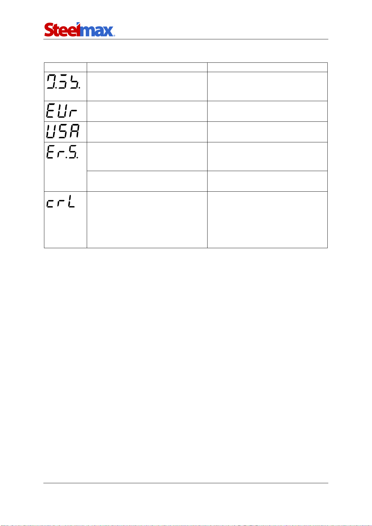
3.4. Troubleshooting
Message
Problem
Solution
Display not fully on after powering.
Contact service center for check
and repair.
Speed shown in centimeters per
minute instead of inches per minute.
Refer to the section “Changing the
unit of speed.”
Speed shown in inches per minute
instead of centimeters per minute.
Refer to the section “Changing the
unit of speed.”
Direction switch not set to ‘O’ when
powering.
Set the direction switch to ‘O’. If the
message still shows, contact service
center for check and repair.
Shown during travel indicates
a malfunction.
Contact service center for check and
repair.
Motor overload. The carriage stops.
Adjust the position of the cables so
that they do not block the carriage.
Remove other objects that block the
carriage or its wheels.
If this message still shows, contact
service center for check and repair.

Torch Runner (HS)
Torch Runner (HS) Operator’s Manual
13
4. MAINTENANCE
Each day:
1. Clean the wheels.
2. Clean the torch nozzle and replace if damaged.
Each week:
1. Clean the teeth of the rack.
Each month:
1. Make sure that the knob and the switches work as intended. Replace if they are
loose or damaged.
2. Examine cables and cords, and replace if damaged.
3. Tighten screws if loose.

Torch Runner (HS)
Torch Runner (HS) Operator’s Manual
14
5. ACCESSORIES
5.1. Track
Increases the cutting precision by forcing straight-line travel. The length of a single
rail is 1800 mm (70.9″) and the V-groove centerline is 152 mm (6″). To connect two
rails, use the 4 mm hex wrench and the connecting plate as shown in the figure.
Part number:
TRO-0475-13-00-00-0
M5x6
5,3
Torch Runner (HS)
Torch Runner (HS) Operator’s Manual
15
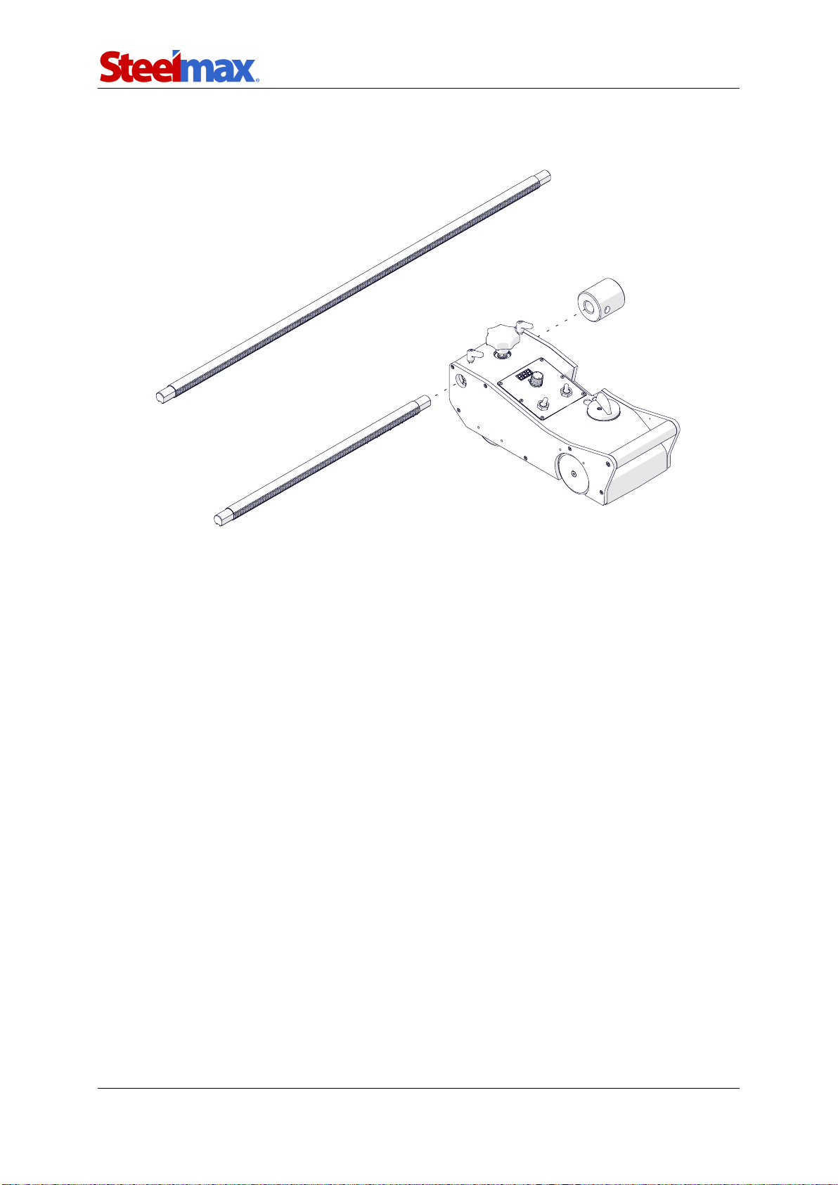
5.2. 1000 mm (39″) rack
Increases the reach of the torch holder.
To remove the rack, use the 3 mm hex wrench to loosen the set screw and remove the
counterweight. Then, loosen the handle of the torch holder and remove the holder.
Next, unlock two rack locking levers and rotate the rack position knob to move the
rack out of the carriage body. Install in reverse order. Put the rack teeth to the side to
engage them with the gear of the knob. If you use the 1000 mm (39″) rack, you may
also need arollersupport or a 2.6 kg counterweight to balance the carriage.
Part number:
RAM-0475-23-00-00-0

Torch Runner (HS)
Torch Runner (HS) Operator’s Manual
16
5.3. 2.6 kg (5.7 lbs) counterweight
Provides balance when using additional holders, a 1000 mm (39″) rack, or a heavier
torch. To remove the counterweight, use the 3 mm hex wrench to loosen the set
screw. Install in reverse order.
5.4. Roller support
Provides balance when using the 1000 mm (39″) rack or a heavier torch.
To install, loosen the handle of the torch holder and remove the holder. Then, put the
supportonto the rack, tighten with the handle, and install the holder again.
Part number:
PWG-0475-10-00-00-0
Part number:
PDT-0475-26-00-00-0

Torch Runner (HS)
Torch Runner (HS) Operator’s Manual
17
5.5. Cable anchor
Attaches the gas cables and the power cord to decrease the load applied on the
torch holder. Install with the 5 mm hex wrench.
5.6. Torch holders
5.6.1. Standard torch holder
For torches with the diameter of 28–35 mm (1.10–1.38″). Allows rough adjustment of
the torch angle.
Part number:
PDT-0475-34-00-00-0
Part number:
UCW-0475-28-00-00-0
M6x30

Torch Runner (HS)
Torch Runner (HS) Operator’s Manual
18
5.6.2. Precise torch holder
For torches with the diameter of 28–35 mm (1.10–1.38″). Allows precise adjustment of
the torch angle.
Use the knob to adjust the vertical position. Install the knob at any side by using
the 2.5 mm hex wrench and the set screw.
To adjust the resistance of the vertical travel, use the 2.5 mm hex wrench to
remove the fixing screws. Then, use the 2 mm hex wrench to rotate the adjusting
screws.
5.6.3. Machine torch holder (for oxy-fuel cutting)
For torches with the diameter of 35 mm (1.38″) that have a rack. The holder allows
adjustment of the vertical position of the torch by using the knob and rough
adjustment of the angle.
Set screw
Adjusting screws
Fixing
screws
Part number:
UCW-0475-08-00-00-0
Part number (35 mm):
UCW-0475-29-00-00-1
Part number (30 mm):
UCW-0475-61-00-00-0

Torch Runner (HS)
Torch Runner (HS) Operator’s Manual
19
5.6.4. Precise machine torch holder (for oxy-fuel cutting)
For torches with the diameter of 35 mm (1.38″) equipped with a rack. The holder
allows adjustment of the vertical position of the torch by using the knob and precise
adjustment of the angle.
5.7. Slide rack holder
Can be put together with torch holders. This allows use of a second torch
independently of the standard torch.
Part number (35 mm):
UCW-0475-42-00-00-1
Part number (30 mm):
UCW-0475-59-00-00-0
Part number:
UCW-0475-15-00-00-1
Bracket

Torch Runner (HS)
Torch Runner (HS) Operator’s Manual
20
To adapt the rack holder for use with a precise torch holder, use the 4 mm hex wrench
and remove four screws from the rack holder. Then, rotate the bracket by 180° and
tighten with the screws. Before you attach a torch holder to the rack holder, remove
the clamping block (part with one or two handles) from the torch holder. Remove the
counterweight or holder in use, and then put the combined holder onto the rack. Next,
rotate the knob to set the combined holder in the required position on the rack.
Other manuals for Torch Runner
1
This manual suits for next models
1
Table of contents


