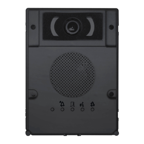
Siedle SET CVSG 850-1 User manual

Produktinformation
Starter-Set
Smart Gateway
für Aufputz
Product information
Smart Gateway
starter kit
for surface mounting
Information produit
Kit de démarrage
Smart Gateway pour
montage en saillie
Opuscolo informativo
sulprodotto
Starter set
SmartGateway in
versione appoggio muro
Productinformatie
Starter-set
Smart Gateway
voor opbouw
Produktinformation
Startsæt Smart Gateway
til frembygning
Produktinformation
Startset Smart Gateway
för utanpåliggande
montering
SET CVSG 850-1

2
1
50 mm
10 mm
3
45
2

3
7
6
8

4
Tb
Tö
Tö
Li
Li
N
L1
b
c
b
c
Ta
TbK
TaK
-
+
-
+
BCV 850-… SNG 850-…
a)
ANG 600-…
TbM
TaM
SG 150-…
LAN
Tö 12 V AC
min. 20 Ohm
230 V AC
N
L1
230 V AC
ETb
ERT
ERT
Gerätebedarf
Hinweis
9
ERT
ETb
TbM
S1
S1
–
+
E1
E1
PE
PE
Ta M
0000000000000
Smart Gateway
SG 150-0
IP 20
www.siedle.com Link
In-Home
Status
Reset
Prog.
10
A0,2s 0,2s 0,2s 0,2s 0,2s 0,2s 0,2s 0,2s 0,2s 0,2s
B0,3s 2s 0,3s 2s 0,3s

5
Bei Videoanlagen müssen folgende
Einbausituationen unbedingt ver-
mieden werden:
• direktes Gegenlicht
• direkte Sonneneinstrahlung
• Bildhintergrund mit großer
Helligkeit
• stark reektierende Wände auf
der gegenüberliegenden Seite der
Kamera
• Leuchten bzw. direkte Lichtquellen
Lieferumfang SETCVSG850-1
• BCV850-1-… E
• SG150-…
• ANG600-…
• SNG850-…
• Siedle-Schraubendreher
• diese Produktinformation
Montage Türstation
1 Gehäusefront abschrauben. Dazu
an der Unterseite des Gehäuses die
Siedle-Schraube lösen. Gehäusefront
nach vorne aufklappen.
2 Aufputzmontage der Türstation.
Empfohlene Einbauhöhe
ca.1,50m/4,9ft bis Gerätemitte.
Bitte beachten: Das Kabel wird im
unteren Bereich der Grundplatte
eingeführt!
3 Das Installationskabel wandnah
abmanteln (ca. 10 mm) und Adern
in die Grundplatte einführen.
Die Grundplatte mit 4 Schrauben
befestigen. Die beiden oberen
Öffnungen mit den Gummistopfen
verschliessen. Installation nach
Anschlussplan vornehmen.
Die Adern dürfen nur im zulässigen
Installationsraum verlegt werden.
4 Der Blickwinkel der Kamera kann
je nach Einbausituation horizontal
und vertikal um ca. 30° vorjustiert
werden. Um die Blickrichtung der
Kamera zu verändern, kann diese in
die gewünschte Richtung positio-
niert werden. Um die Blickrichtung
zu verändern, die beiden Kreuz
schlitzschrauben etwas lösen.
Deutsch
Anwendung
Das Starter-Set SmartGateway für
Aufputz beinhaltet alle benötigten
Komponenten um den Türruf mit
Video auf dem Smartphone ent-
gegen zu nehmen und die Tür zu
öffnen.
Erweiterbarkeit
Das Starter-Set kann durch nach-
stehende Komponenten erweitert
werden. Der Gesamtausbau darf
10 Teilnehmer nicht überschreiten,
wobei eine Türstation zwei
Teilnehmer belegt.
• Video-Innenstation Siedle Basic
• Audio-Innenstation Siedle Basic
• Türstation des In-Home-Bus
Systems
Gegebenenfalls werden weitere
Systemkomponenten benötigt.
Leistungsmerkmale BCV850-1-...
• integrierte Kamera mit automati-
scher Tag-/Nachtumschaltung, LED-
Beleuchtung und 2-stuger Heizung
• integrierter Türlautsprecher
• Sprachlautstärke einstellbar
• Anzahl integrierter Ruftasten: 1
• akustische Tastenquittierung akti-
vierbar
• hinterleuchtete Namensschilder
frontseitig wechselbar
• für die Aufputzmontage mit
Verblendung aus gebürstetem
Edelstahl
Leistungsmerkmale SG150-…
• Unterstützung der Siedle App für
iPhone oder Android-Smartphone
• Bis zu 10 IP-Teilnehmer (lizenz-
pichtig, 5 Lizenzen inklusive)
• Gruppenruf von bis zu 6 IP-Teil-
nehmer
• Parallelruf zu IP-Teilnehmern und
In-Home-Bus-Endgeräten möglich
• Direkte Türanwahl aus Liste
• Zentraler Bildspeicher mit automa-
tischer zeitgesteuerter Löschung der
Bilder (datenschutzkonform)
Leistungsmerkmale Siedle App
• Türruf per App
• Mobilfunkanbindung
• Weltweite Erreichbarkeit
• Sichere und intuitive App-
Bedienung
Leistungsmerkmale SNG850-…:
• 10 Bus-Adressen für die Versor-
gung der Bus-Teilnehmer
• integrierter Türöffner- und Licht-
kontakt
• Programmierung: manuell oder
per BPS650-… (Windows-PC) mit
ZBVG650-… und PRI602-… USB
Elektrische Spannung
• Einbau, Montage und Service-
arbeiten elektrischer Geräte dürfen
ausschließlich durch eine Elektro-
Fachkraft erfolgen.
Bei Nichtbeachten besteht die
Gefahr schwerer gesundheitlicher
Schäden oder Lebensgefahr durch
elektrische Stromschläge.
• Betrieb in einer Höhenlage bis
2000m über dem Meeresspiegel.
• EN 62368-1 beachten!
In der Gebäudeinstallation muss
ein allpoliger Netzschalter mit
einer Kontaktöffnung von mindes-
tens 3mm vorhanden sein. Das
Netzgerät darf nicht Tropf- oder
Spritzwasser ausgesetzt werden!
Für ausreichende Belüftung ist zu
sorgen, insbesondere ist darauf zu
achten, dass die Lüftungsschlitze
nicht abgedeckt werden.
• Bei Verwendung von Litze als
Kabelmaterial sind diese zwingend
mit Aderendhülsen zu versehen.
Elektrostatische Auadung
Durch elektrostatische Auadung
kann bei direktem Kontakt mit der
Leiterplatte das Gerät zerstört
werden. Vermeiden Sie daher ein
direktes Berühren der Leiterplatte.

6
Kamera in die gewünschte Richtung
positionieren. Mit den beiden Kreuz-
schlitzschrauben anschließend die
gewünschte Position xieren.
5 Je nach Einbauumgebung kann
es erforderlich sein, die Sprachlaut
stärke der Türstation zu verändern,
um eine klare Sprachübertragung zu
ermöglichen.
6 Gehäusefront oben auf der
Grundplatte einhängen und
schließen. Die Schraube an der
Unterseite des Gehäuses festdrehen.
Montage im Verteilerschrank
7 Geräte auf Hutschiene montieren.
Beschriftung
8 Namensschild von der Außenseite
z.B. mit einem Schlitzschrauben
dreher vorsichtig öffnen und
Schrifteinlage entnehmen. Zum
Einsetzen das Namensschild mit
leichtem Druck einrasten.
Installation
9 Anschluss nach entsprechendem
Schaltplan vornehmen.
Hinweis
a) Kamerazweig und Monitorzweig
müssen getrennt verlegt sein und
dürfen nicht im gleichen Kabel
liegen. Es kann sonst zu Störungen
beim Bildaufbau kommen.
Reichweite
Die In-Home-Businstallation muss
bei J-Y(St)Y auf einem Adernpaar
erfolgen, bei YR-Leitung auf 2
nebeneinanderliegenden Adern.
Bei J-Y(St)Y ist die Möglichkeit einer
Störbeeinussung geringer.
SNG850-… zur Türstation max.
50m,
SNG850-… zum entferntesten
Innengerät max. 50m, bei 0,8mm
Aderdurchmesser.
Bei einem Aderdurchmesser von
0,6mm halbiert sich die Reichweite.
Klemmenbelegung BCV850-1-…
TaK, TbK In-Home-Bus
Kamerazweig
Tö (c) Relaiskontakt Türöffner
b, c Versorgung 12VAC
für Kameraheizung
Klemmenbelegung SG150-…
TaM , TbM In-Home-Bus
Monitorzweig
+, - Versorgungsspannung
20–50VDC
ETb, ERT Etagenruftaste
S1, S1 potentialfreier Kontakt
max.30VAC/DC, 2A
E1, E1 galvanisch getrennt
4–30VDC, 10mA
PE, PE Potentialausgleich LAN
Klemmenbelegung ANG600-…
L1, N Netzanschluss
+, - Ausgangsspannung
48VDC, 800mA
Klemmenbelegung SNG 850-…
L1, N Netzanschluss
Ta, Tb In-Home-Bus
b, c Versorgungsspannung
12VAC
Tö, Tö Relaiskontakt Türöffner
Li, Li Relaiskontakt Licht
Technische Daten BCV850-1-…
Farbsystem: PAL
Bildaufnehmer: CMOS-Sensor 1/3"
756x504 Pixel
Auösung: 550 TV-Linien
Objektiv: 3,7mm
Blickwinkel: horizontal ca.65°,
vertikal ca.50°
Verstellbereich mechanisch:
30° horizontal/vertikal
2-stuge Heizung: 12VAC,
max.110mA
Betriebsspannung: über
In-Home-Bus
Kontaktart: Schließer 24V, 2A
Schutzart: IP54, IK8
Umgebungstemperatur:
–20°Cbis+40°C
Abmessungen (mm) BxHxT:
82x226x35
Technische Daten SG150-…
Betriebsspannung: 20–50VDC,
PoE nach 802.3af
Betriebsstrom: max.400mA
Schutzart: IP20
Umgebungstemperatur:
0°Cbis+40°C
Teilungseinheit (TE): 6
Abmessungen (mm) BxHxT:
107x109x60
Technische Daten ANG600-…
Betriebsspannung: 100–240VAC,
+/-10%, 50/60Hz
Betriebsstrom: 0,5–1A
Ausgangsspannung: 48VDC
Ausgangsstrom: 800mA
Absicherung: primär thermisch
abgesichert, sekundärseitig kurz-
schlussfest
Kontaktart: Umschalter
max.250VAC, 6A
Schutzart: IP20
Umgebungstemperatur:
0°Cbis+40°C
Teilungseinheit (TE): 6
Abmessungen (mm) BxHxT:
107x89x60
Technische Daten SNG850-…
Betriebsspannung: 230VAC,
+/-10%, 50/60Hz
Betriebsstrom: 200mA
Ausgangsspannung: 27,5VDC,
12VAC
Ausgangsstrom: 0,5ADC, 1AAC
Absicherung: Primär Si
1T250mAL, sekundär kurzschluss-
fest
Kontaktart: 2 Schließer 24V, 2A
Schutzart: IP30
Umgebungstemperatur:
0°Cbis+40°C
Teilungseinheit (TE): 9
Abmessungen (mm) BxHxT:
162x89x60

7
Anzeige LED1 „Betrieb“
LED blinkt gleichmäßig
(Systemhochlauf) 0,3s 0,3s 0,3s 0,3s 0,3s usw.
LED blinkt kurz auf, lange aus
(Betriebsanzeige, Anlage in Funktion) 1s 20ms 1s 20ms usw.
LED blinkt kurz an, lange aus
(Programmiermodus aktiv) 0,3s 2s 0,3s usw.
LED immer an
(Plug+Play Programmierung ist aktiv)
Anzeige LED2 „Störung“
LED blinkt ungleichmäßig
(Mehr als 10 Teilnehmer) 2s 0,3s 0,3s 0,3s usw.
LED blinkt ungleichmäßig
Ungeeignetes Gerät im Plug+Play
Modus angeschlossen
0,3s 0,3s 0,2s 2s usw.
LED blinkt gleichmäßig
Keine Türstation im Plug+Play
Modus angeschlossen
2s 2s usw.
10 Smart Gateway SG150-…
Element LED-Betriebszustand Funktion
Link leuchtet grün Verbindung zum LAN besteht
aus keine Verbindung zum LAN
In-Home blinkt grün Teilnehmer aktiviert im Programmiermodus manuell
(siehe Tabelle A)
Bus-Adressen reservieren (siehe Tabelle B)
leuchtet grün Betriebszustand
aus nicht betriebsbereit
Status blinkt grün Systemhochlauf (siehe Tabelle A)
leuchtet grün Betriebszustand
leuchtet rot nicht betriebsbereit
blinkt abwechselnd grün/rot Update
Reset kurze Betätigung Das Gerät wird neu gestartet
Prog. lange Betätigung 3Sekunden Programmiermodus manuell (Gerät aktivieren)
Beschreibung der Anzeige- und Bedienelemente
Set-Netzgerät SNG850-…

8
Link
In-Home
Status
Reset
Prog.
4 Sek.
1Programmiermodus am
SNG850-… aktivieren. Prog.- Mode
Taste kurz drücken, die LED1 blinkt
im 2Sekunden Rhythmus.
4An der Türstation die gewünschte
Ruftaste für 4Sekunden gedrückt
halten, bis am Türlautsprecher ein
langgezogener Ton zu hören ist. Die
Ruftaste ist jetzt dem Bus-Innengerät
zugeordnet.
2An der Türstation die Program-
miertaste 4Sekunden gedrückt
halten. Danach ist ein langgezogener
Quittungston zu hören, der alle
5Sekunden kurz wiederholt wird,
solange der Programmiermodus
aktiv ist.
5Programmiervorgang beenden,
dazu am Set-Netzgerät die Prog.-
Mode Taste drücken. Die Ruftaste
ist jetzt dem SmartGateway
zugewiesen.
3 Prog.-Taste für 4Sekunden
drücken. Danach blinkt die LED
In-Home im Sekunden-Rhythmus.
Das Smart Gateway/Smart
Gateway Professional ist jetzt im
Programmiermodus.
Programmierung

9
Inbetriebnahme Siedle App
Voraussetzungen:
• Anlage komplett aufgebaut
• Programmierung abgeschlossen
• Laptop und Smart Gateway
benden sich im gleichen Netzwerk
• IP-Adresse des Smart Gateway
bekannt
Verwendung von einer App
1 Webbrowser öffnen und
IP-Adresse des Smart Gateway
eingeben.
2 Anmeldeseite öffnet sich,
Benutzername„admin“ und
Passwort„admin“ eingeben.
3 In den Bereich Netzwerk-Teil-
nehmer, Unterpunkt IP-Teilnehmer
einen neuen IP-Teilnehmer anlegen.
4 Namen frei vergeben z.B.
Benutzer1, den Bus-Adressverweis
der vordeniert ist auswählen und
mit weiter bestätigen.
5 QR-Code mit der Siedle App
scannen oder ausdrucken.
6 Die Inbetriebnahme ist abge-
schlossen, Browser schließen.
Verwendung von bis zu 6 Apps in
einer IP-Gruppe
1 Webbrowser öffnen und
IP-Adresse des Smart Gateway
eingeben.
2 Anmeldeseite öffnet sich,
Benutzername„admin“ und
Passwort„admin“ eingeben.
3 In den Bereich Netzwerk-Teil-
nehmer, Unterpunkt IP-Teilnehmer
einen neuen IP-Teilnehmer anlegen.
4 Namen frei vergeben z.B.
Benutzer1, den Bus-Adressverweis
nicht auswählen und mit weiter
bestätigen.
5 QR-Code mit der Siedle App
scannen oder ausdrucken.
6 Punkt 3 bis 5 solange wiederholen
bis alle Appbenutzer angelegt sind.
7 In den Bereich Netzwerk-Teil-
nehmer, Unterpunkt IP-Gruppen
eine neue IP-Gruppe anlegen.
8 Namen frei vergeben z.B.
Gruppe1, den Bus-Adressverweis*
der vordeniert ist auswählen, die
zuvor angelegten IP-Teilnehmer hin-
zufügen und speichern.
9 Die Inbetriebnahme ist abge-
schlossen, Browser schließen.
*Sollte der Bus-Adressverweis
nicht verfügbar sein, ist er bereits
einem anderen IP-Teilnehmer oder
IP-Gruppe zugewiesen und muss
dort gelöscht werden.

10
Application
The SmartGatewaystarter kit for
surface mounting contains all the
components you need to accept a
door call with video on your smart-
phone and open the door.
Upgrade capability
The starter kit can be extended with
the following components. The
overall extension must not exceed
10users, whereby one door station
supports two users.
• Video indoor station Siedle Basic
• Audio indoor station Siedle Basic
• Door station of the In-Home bus
system
Further system components maybe
needed.
Performance features
BCV850-1-...
• Integrated camera with automatic
day/night switchover, LED lighting
and 2-stage heating
• Integrated door loudspeaker
• Adjustable voice volume
• Number of integrated call but-
tons: 1
• Acoustic button acknowledgement
can be activated
• Backlit nameplates exchangeable
from the front
• for surface mounting with brushed
stainless steel panel
Performance features SG150-…
• Support for the Siedle app for
iPhone or Android smartphone
• Up to 10IP users (subject to
licence, 5licences included)
• Group call of up to 6IP users
• Parallel call to IP users and
In-Home bus end devices possible
• Direct door dialling from list
• Central video memory with auto-
matic time controlled deletion of
images (data protection compliant)
Performance features Siedle App
• Door calls using the app
• Mobile network connection
• Worldwide accessibility
• Secure and intuitive app operation
English
Performance features
SNG850-…:
• 10 bus addresses for supplying the
bus users
• Integrated door release and light
contact
• Programming: manual or via
BPS650-… (WindowsPC) with
ZBVG650-… and PRI602-…USB
Electrical voltage
• Mounting,installation and ser-
vicing work on electrical devices may
only be performed by a suitably
qualied electrician. Failure to
observe this regulation could result
in the risk of serious damage to
health or fatal injury due to electric
shocks.
• Operation at an altitude of up to
2000m above sea level.
• Observe EN 62368-1! In a building
installation, an all-pole mains switch
with a contact opening of at least
3mm must be provided. The device
must not be exposed to water drops
or sprayed water! Sufcient ventila-
tion must be ensured. Pay particular
attention to ensure that ventilation
slots are not covered.
• When using stranded cores as
cable material, these must be tted
with wire end ferrules without fail.
Electrostatic charging
As a result of electrostatic charging,
direct contact with the circuit board
can result in destruction of the
device. Direct contact with the circuit
board must therefore be avoided.
In the case of video systems,the fol-
lowing mounting situation must be
avoided at all costs:
• direct backlight
• direct sunlight
• very bright image backgrounds
• highly reective walls opposite the
camera
• lamps or direct light sources
Scope of supply SETCVSG850-1
• BCV850-1-… E
• SG150-…
• ANG600-…
• SNG850-…
• Siedle screwdriver
• This product information
Door station mounting
1 Unscrew the front of the housing.
To do this, release the Siedle screw
on the underneath of the housing.
Hinge the front of the housing
forward.
2 Surface mounting the door sta-
tion. Recommended mounting
height appr. 1.50m /4.9ft. to centre
device. Please note: The cable is
inserted in the lower area of the
base plate!
3 Strip back the installation cable
close to the wall (appr. 10 mm)
and insert the cores into the base
plate. Fasten the base plate using 4
screws. Close the two openings at
the top using rubber stoppers. Install
in accordance with the terminal
diagram.
The cores may only be laid in the
admissible installation space.
4 The pick-up angle of the camera
can be mechanically preadjusted on
the vertical and horizontal by appr.
30° depending on the mounting
situation. To change the pick-up
direction of the camera, it can be
positioned in the required direction.
To change the pick-up direction,
loosen the two cross-head screws
slightly. Position the camera in the
required direction. Then x the

11
required position using the two
cross-head screws.
5 Depending on the installation
environment, it may be necessary
to change the door station speech
volume in order to permit clear
speech transmission.
6 Hook the front of the housing
onto the base plate at the top and
close. Tighten the screw on the
underneath of the housing.
Mounting in distribution cabinet
7 Mount the devices on the top
hat rail.
Lettering
8 Open the nameplate from the
outside, for example using a at
bladed screwdriver, and carefully
remove the inscription insert. To
insert the nameplate, lock into place
by exerting light pressure.
Installation
9 Connect in accordance with the
relevant circuit diagram.
Note
a) The camera branch and monitor
branch must be laid separately and
must not be located in the same
cable. This can result in disturbance
to the picture composition.
Range
The In-Home bus must be installed
on one pair of cores when using
J-Y(St)Y, and when using a YR
conductor, on two YR cores posi-
tioned side by side. Using J-Y(St)Y
conductors reduces the likelihood of
interference.
SNG850-… to door station max.
50m,
SNG850-… to the most remote
indoor device max. 50m, with
0.8mm core diameter.
With a core diameter of 0.6mm, the
range is halved.
2-step heating: 12VAC,
max.110mA
Operating voltage: via In-Home bus
Contact type: contact 24V, 2A
Protection system: IP54, IK8
Ambient temperature:
–20°Cto+40°C
Dimensions (mm) WxHxD:
82x226x35
Specications SG150-…
Operating voltage: 20–50VDC,
PoE in accordance with 802.3af
Operating current: max.400mA
Protection system: IP20
Ambient temperature:
0°Cto+40°C
Horizontal pitch (HP): 6
Dimensions (mm) WxHxD:
107x109x60
Specications ANG600-…
Operating voltage: 100–240VAC,
+/-10%, 50/60Hz
Operating current: 0.5–1A
Output voltage: 48VDC
Output current: 800mA
Fusing: primary thermal fuse,
secondary short circuit proof
Contact type: changeover switch
max.250VAC, 6A
Protection system: IP20
Ambient temperature:
0°Cto+40°C
Horizontal pitch (HP): 6
Dimensions (mm) WxHxD:
107x89x60
Specications SNG850-…
Operating voltage: 230VAC,
+/-10%, 50/60Hz
Operating current: 200mA
Output voltage: 27.5VDC, 12VAC
Output current: 0.5ADC, 1AAC
Fusing: Primary fuse 1T250mAL,
secondary short circuit proof
Contact type: 2 n.o. contacts 24V,
2A
Protection system: IP30
Ambient temperature:
0°Cto+40°C
Horizontal pitch (HP): 9
Dimensions (mm) WxHxD:
162x89x60
Terminal assignment
BCV850-1-…
TaK, TbK In-Home bus camera
branch
Tö (c) Relaycontact door
release
b, c 12VAC supply for
camera heating
Terminal assignment SG150-…
TaM , TbM In-Home bus monitor
branch
+, - Supplyvoltage
20–50VDC
ETb, ERT Storeycall button
S1, S1 Potential-free contact
max.30VAC/DC, 2A
E1, E1 galvanically isolated
4–30VDC, 10mA
PE, PE Equipotential bonding
LAN
Terminal assignment ANG600-…
L1, N Power connection
+, - Output voltage
48VDC, 800mA
Terminal assignment SNG 850-…
L1, N Power connection
Ta, Tb In-Home bus
b, c Power supply12VAC
Tö, Tö Relaycontact door
release
Li, Li Relaycontact light
Specications BCV850-1-…
Colour system: PAL
Image pick-up: CMOS sensor 1/3"
756x504 Pixel
Resolution: 550 TVlines
Lens: 3,7mm
Pick-up angle: horizontal appr.65°,
vertical appr.50°
Mechanical adjustment range: 30°
horizontal/vertical

12
Display LED1 “Operation“
LED ashes evenly
(System ramp-up) 0,3s 0,3s 0,3s 0,3s 0,3s etc.
LED ashes short on,long off
(Operation display, system is functional) 1s 20ms 1s 20ms etc.
LED ashes short on,long off
(Programming mode active) 0,3s 2s 0,3s etc.
LED remains alight
(Plug+Playprogramming is active)
Display LED2 “Fault“
LED ashes unevenly
(More than 10 users) 2s 0,3s 0,3s 0,3s etc.
LED ashes unevenly
Unsuitable device connected in
Plug+Play mode
0,3s 0,3s 0,2s 2s etc.
LED ashes evenly
No door station connected in
Plug+Play mode
2s 2s etc.
10 Smart Gateway SG150-…
Element LED operating status Function
Link lights up in green Connection to LAN established
off No connection to the LAN
In-Home ashes green User activated mode manually (see Table A)
Reserve bus addresses (see Table B)
lights up in green Operating status
off Not readyfor operation
Status ashes green System start (see table A)
lights up in green Operating status
lights up in red Not readyfor operation
Flashes alternately green/red Update
Reset Press briey The device is restarted
Prog. Hold down for 3seconds Programming manual (Activate device)
Description of display and operating elements
Set line rectier SNG850-…

13
Link
In-Home
Status
Reset
Prog.
4 Sek.
1Activate the programming mode
on the SNG850-… Briey press the
programming mode button, LED1
ashes every 2seconds.
4On the door station,press and
hold the desired call button for
4seconds until a sustained tone can
be heard from the door loudspeaker.
The call button is now assigned to
the bus indoor device.
2At the door station,hold down the
programming button for 4seconds.
A protracted acknowledgement tone
is then audible which is repeated
every 5seconds as long as the pro-
gramming mode remains active.
5End the programming process by
pressing the programming mode
button on the set line rectier. The
call button is now assigned to the
SmartGateway.
3 Press the programming button for
4seconds. The In-Home LED then
ashes in a one-second rhythm.
The Smart Gateway/Smart Gateway
Professional is now in programming
mode.
Programming

14
Commissioning Siedle App
Conditions:
• System fully set up
• Programming complete
• Laptop and Smart Gateway are in
the same network
• IP address of the Smart Gateway
is known
Using one app
1 Open your web browser and enter
the Smart Gateway’s IP address.
2 The login page appears. Enter
the username“admin” and the
password“admin”.
3 Create a new IP user in the
Network users area, under IP users.
4 Assign a name freely, e.g. User1,
select the bus address reference
which is pre-dened and click Next
to conrm.
5 Scan the QR code with the Siedle
app or print it out.
6 Commissioning is complete. Close
the browser.
Using up to 6apps in an IP group
1 Open your web browser and enter
the Smart Gateway’s IP address.
2 The login page appears. Enter
the username“admin” and the
password“admin”.
3 Create a new IP user in the
Network users area, under IP users.
4 Assign a name freely, e.g. User1,
do not select the bus address refer-
ence and click Next to conrm.
5 Scan the QR code with the Siedle
app or print it out.
6 Repeat points 3 to 5 until all app
users have been created.
7 Create a new IP group in the
Network users area, under IP groups.
8 Assign a name freely, e.g. Group1,
select the bus address reference*
which is pre-dened, add the IP
users created previously and save.
9 Commissioning is complete. Close
the browser.
*If the bus address reference is not
available, it is already assigned to
another IP user or IP group and must
be deleted there.

15
Application
Le kit de démarrage Smart Gateway
pour montage en saillie contient tous
les composants nécessaires pour rece-
voir l‘appel de porte avec vidéo sur le
smartphone et pour ouvrir la porte.
Extensibilité
Le kit de démarrage peut être com-
plété par les composants suivants.
L‘installation complète ne doit pas
dépasser 10 postes tout en sachant
qu‘une platine de rue occupe deux
postes.
•Platine intérieure vidéo Siedle Basic
• Platine intérieure audio Siedle Basic
• Platine de rue du système de bus
In-Home
Le cas échéant, d’autres composants
système sont nécessaires.
Caractéristiques fonctionnelles
BCV850-1-...
• caméra intégrée avec commutation
jour/nuit, éclairage à LED et chauffage
à 2 niveaux
• haut-parleur de porte intégré
• volume de la voix réglable
• nombre de touches d’appel inté-
grées : 1
•actionnement de touche avec signal
acoustique activable
• plaquettes de nom rétro-éclairées
remplaçables par l’avant
• pour montage en saillie avec cache
en acier inoxydable brossé
Caractéristiques fonctionnelles
SG150-…
• Prise en charge de l‘application
Siedle pour iPhone ou smartphone
Android
• Jusqu‘à 10postes IP (soumis à
licence, 5licences comprises)
• Appel groupé jusqu‘à 6postes IP
• Appel parallèle possible vers des
postes IP et des terminaux bus
In-Home
• Sélection directe de la porte dans
la liste
• Mémoire d‘images avec effacement
automatique des images temporisé
(conforme à la protection des don-
nées)
Français
Caractéristiques fonctionnelles
Siedle App
• Appel de porte via application
• Connexion au réseau de téléphonie
mobile
• Accessibilité à l‘échelle mondiale
• Utilisation sûre et intuitive de
l‘application
Caractéristiques fonctionnelles
SNG850-…:
• 10 adresses bus pour l’alimentation
des postes bus
• Contact gâche et lumière intégrés
• Programmation: manuelle ou
via BPS650-… (PC Windows) avec
ZBVG650-… et PRI602-…USB
Tension électrique
• L’installation, le montage et l’entre-
tien d’appareils électriques ne doivent
être réalisés que par un spécialiste en
électricité. Le fait de ne pas respecter
cette consigne expose à un risque de
blessures graves ou à un danger de
mort par décharges électriques.
• Exploitation à une altitude allant
jusqu’à 2000m au-dessus du niveau
de la mer.
• Respecter la norme EN 62368-1!
Un interrupteur général bipolaire,
avec une distance de contact ouvert
de 3mm au minimum, doit être pré-
sent dans l’installation du bâtiment.
L’appareil ne doit pas être exposé
aux gouttes d’eau ou aux projections
d’eau! Prévoir une ventilation suf-
sante et veiller en particulier à ne pas
masquer les fentes d’aération.
•Si l’on utilise des torons à titre de
câbles, ceux-ci doivent impérative-
ment être munis d’embouts.
Charge électrostatique
La charge électrostatique peut
détruire l’appareil en cas de contact
direct avec la carte de circuits
imprimés. Evitez par conséquent tout
contact direct avec la carte de circuits
imprimés.
Pour les installations vidéo, les situa-
tions de montage suivantes doivent
impérativement être évitées :
• un contre-jour direct
• le rayonnement direct du soleil
• un fond d’une grande luminosité
• des parois très rééchissantes des
parois très rééchissantes dans l’axe
de prise de vue de la caméra
• des lampes ou des sources de
lumière directe
Etendue de la fourniture
SETCVSG850-1
• BCV850-1-… E
• SG150-…
• ANG600-…
• SNG850-…
• Siedle tournevis
• La présente information produit
Montage platine de rue
1 Dévisser la façade du boîtier.
A ces ns, desserrer la Siedle vis sur la
face inférieure du boîtier. Rabattrer la
façade du boîtier vers l’avant.
2 Montage en saillie de la platine de
rue. Hauteur de montage conseillée
env. 1,50m/4,9pieds du centre de
l’appareil. A noter : Le câble s’intro-
duit dans la zone inférieure du socle!
3Dénuder le câble d’installation à
proximité de la paroi (env. 10 mm) et
introduire les ls dans le socle. Fixer
le socle à l’aide de 4 vis. Obturer les
deux orices supérieurs à l’aide des
bouchons en caoutchouc. Effectuer
l’installation conformément au
schéma de raccordement.
Les ls ne doivent être posés que
dans la zone d’installation autorisée.
4 L’angle de visée de la caméra
peut être préajusté, en fonction de
la situation de montage, horizon-
talement et verticalement sur 30°
environ. Pour modier le sens de
visée de la caméra, il est possible de
positionner cette dernière dans le
sens souhaité. Pour modier le sens
de visée, desserrer un peu les deux vis
à empreinte cruciforme. Positionner la
caméra dans le sens souhaité. Ensuite,
xer la position souhaitée à l’aide des

16
deux vis à empreinte cruciforme.
5 En fonction de l’environnement de
montage, il peut être nécessaire de
modier le volume audio de la platine
de rue an de permettre une trans-
mission claire de la voix.
6Accrocher la façade du boîtier en
haut du socle, et la fermer. Bloquer la
vis sur la face inférieure du boîtier.
Montage dans l’armoire de dis-
tribution
7Monter les appareils sur barre DIN.
Marquage
8 Ouvrir l’étiquette avec précautions
par le côté extérieur, p. ex. à l’aide
d’un tournevis pour vis à tête fendue,
et retirer l’insert de marquage. Pour
la mise en place de l’étiquette,
l’encliqueter en exerçant une légère
pression.
Installation
9 Procéder au raccordement confor-
mément au schéma de câblage cor-
respondant.
Remarque
a) La branche caméra et la branche
moniteur doivent être posées sépa-
rément et elles ne doivent pas se
trouver dans le même câble. Sinon,
il peut se produire des perturbations
d’images.
Portée
L’installation bus In-Home doit se faire
sur une paire de ls pour
J-Y(St)Y et sur deux ls côte à côte
pour la ligne YR. Dans le cas de
J-Y(St)Y, la possibilité d’une inuence
parasite est plus faible.
SNG850-… vers la platine de rue
max.50m,
SNG850-… vers l’appareil intérieur
le plus éloigné max. 50m, pour un
diamètre de l de 0,8mm.
Pour un diamètre de l de 0,6mm, la
portée est divisée par deux.
Implantation des bornes
BCV850-1-…
TaK, TbK Bus In-Home branche
caméra
Tö (c) Contact de relais gâche
b, c Alimentation 12VAC
pour le chauffage de la
caméra
SG150-…
TaM , TbM Bus In-Home branche
moniteur
+, - Tension d’alimentation
20–50VDC
ETb, ERT Touche d’appel d’étage
S1, S1 contact sans potentiel
max.30VAC/DC, 2A
E1, E1 isolée galvaniquement
4–30VDC, 10mA
PE, PE Équilibre de potentiel
LAN
ANG600-…
L1, N Raccordement au
secteur
+, - Tension de sortie
48VDC, 800mA
SNG850-…
L1, N Raccordement au
secteur
Ta, Tb Bus In-Home
b, c Tension d’alimentation
12VAC
Tö, Tö Contact de relais gâche
Li, Li Contact de relais
lumière
Caractéristiques techniques
BCV850-1-…
Système couleur : PAL
Appareil de prise de vues : Capteur
CMOS 1/3" 756x504 pixels
Résolution : 550 lignesTV
Objectif : 3,7mm
Angle de visée : horizontal
65°environ, vertical 50°environ
Plage de réglage mécanique :
30° horizontalement/verticalement
Chauffage à 2 niveaux : 12VAC,
max.110mA
Tension d’entrée : du bus In-Home
Type de contact : Contact de travail
24V, 2A
Indice de protection : IP54, IK8
Température ambiante :
–20°Cà+40°C
Dimensions (mm) lxHxP :
82x226x35
Caractéristiques techniques
SG150-…
Tension d’entrée : 20–50VDC,
PoE selon 802.3af
Courant de service : max.400mA
Indice de protection : IP20
Température ambiante :
0°Cà+40°C
Unité de Division (UD) : 6
Dimensions (mm) lxHxP :
107x109x60
Caractéristiques techniques
ANG600-…
Tension d’entrée : 100–240VAC,
+/-10%, 50/60Hz
Courant de service : 0,5–1A
Tension de sortie : 48VDC
Courant de sortie : 800mA
Protection : Primaire thermiquement
isolée, secondaire résistant aux
courts-circuits
Type de contact : Inverseur
max.250VAC, 6A
Indice de protection : IP20
Température ambiante :
0°Cà+40°C
Unité de Division (UD) : 6
Dimensions (mm) lxHxP :
107x89x60
Caractéristiques techniques
SNG850-…
Tension d’entrée : 230VAC,
+/-10%, 50/60Hz
Courant de service : 200mA
Tension de sortie : 27,5VDC,
12VAC
Courant de sortie : 0,5ADC, 1AAC
Protection : Primaire Si 1T250mAL,
secondaire résistant aux courts-circuits
Type de contact : 2 contacts de travail
24V, 2A
Indice de protection : IP30
Température ambiante :
0°Cà+40°C
Unité de Division (UD) : 9
Dimensions (mm) lxHxP :
162x89x60

17
Afchage LED1 “Fonctionnement“
La LED clignote régulièrement
(Montée en vitesse du système) 0,3s 0,3s 0,3s 0,3s 0,3s etc.
La LED s’allume brièvement, reste long-
temps éteinte (Afchage du fonction-
nement, installation en fonction)
1s 20ms 1s 20ms etc.
La LED s’allume brièvement, reste long-
temps éteinte (Mode programmation
actif)
0,3s 2s 0,3s etc.
LED éclairée en permanence (La pro-
grammation Plug+Play est active)
Afchage LED2 “Anomalie“
La LED clignote irrégulièrement
(Plus de 10 abonnés) 2s 0,3s 0,3s 0,3s etc.
La LED clignote irrégulièrement
Appareil inapproprié raccordé en
mode Plug+Play
0,3s 0,3s 0,2s 2s etc.
La LED clignote régulièrement
Pas de platine de rue raccordée en
mode Plug+Play
2s 2s etc.
10 Smart Gateway SG150-…
Élément Etat de service des LEDS Fonction
Link éclairée en vert La liaison avec le LAN est présente
éteinte Pas de liaison avec le LAN
In-Home clignote en vert Poste activé en mode programmation manuel (voir
tableau A)
Réserver les adresses bus (voir tableau B)
éclairée en vert État de service
éteinte Pas en ordre de fonctionnement
Status clignote en vert Montée en vitesse du système (voir tableau A)
éclairée en vert État de service
éclairée en rouge Pas en ordre de fonctionnement
Clignote alternativement en vert/
rouge
Mise à jour
Reset Appui bref L’appareil redémarre
Prog. Appui long 3 secondes Mode de programmation manuelle (Activer l’appareil)
Description des éléments d’afchage et de commande
Bloc d’alimentation du kit SNG850-…

18
Link
In-Home
Status
Reset
Prog.
4 Sek.
1Activer le mode programmation
sur le SNG850-… Appuyer briève-
ment sur la touche mode prog., la
LED1 clignote toutes les 2secondes.
4Sur la platine de rue, appuyer sur
la touche d’appel souhaitée pendant
4secondes, jusqu’à ce que l’on
entende une tonalité longue sur le
haut-parleur de porte. La touche
d’appel est maintenant affectée à
l’appareil intérieur bus.
2Sur la platine de rue, maintenir la
touche de programmation appuyée
pendant 4secondes. On perçoit
ensuite une tonalité d’acquitte-
ment longue qui revient toutes les
5secondes brièvement, tant que le
mode programmation est actif.
5Pour mettre n au processus de
programmation, appuyer sur la
touche mode prog. du bloc d'ali-
mentation du kit. La touche d'appel
est maintenant affectée à la Smart
Gateway.
3 Appuyer sur la touche prog. pen-
dant 4secondes. La LED In-Home
clignote ensuite toutes les secondes.
La Smart Gateway/Smart Gateway
Professional se trouve maintenant en
mode de programmation.
Programmation

19
Mise en service Siedle App
Conditions préalables:
• Installation entièrement assemblée
• Programmation terminée
• L‘ordinateur portable et la Smart
Gateway se trouvent dans le même
réseau
• Adresse IP de la Smart Gateway
connue
Utilisation d‘une application
1 Ouvrir le navigateur Web et saisir
l‘adresse IP de la Smart Gateway.
2 La page de connexion s’ouvre,
saisir l’identifiant“admin” et le
mot de passe“admin”.
3 Créer un nouveau poste IP dans
le sous-menu Postes IP de la zone
Postes du réseau.
4 Attribuer un nom quelconque,
par ex. Utilisateur1, sélectionner la
référence d‘adresse bus prédénie et
conrmer avec Continuer.
5 Scanner ou imprimer le code QR à
l‘aide de l‘application Siedle.
6 La mise en service est terminée,
fermer le navigateur.
Utilisation de jusqu‘à 6 applica-
tions dans un groupe IP
1 Ouvrir le navigateur Web et saisir
l‘adresse IP de la Smart Gateway.
2 La page de connexion s'ouvre,
saisir l'identifiant“admin” et le
mot de passe“admin”.
3 Créer un nouveau poste IP dans
le sous-menu Postes IP de la zone
Postes du réseau.
4 Attribuer un nom quelconque,
par ex. Utilisateur1, ne pas sélec-
tionner la référence d'adresse bus et
conrmer avec Continuer.
5 Scanner ou imprimer le code QR à
l‘aide de l‘application Siedle.
6 Répéter les points 3 à 5 jusqu‘à ce
que tous les utilisateurs de l‘applica-
tion soient créés.
7 Créer un nouveau groupe IP dans
le sous-menu Groupes IP de la zone
Postes du réseau.
8 Attribuer un nom quelconque,
par ex. Groupe1, sélectionner la
référence d‘adresse bus* prédénie,
ajouter et enregistrer les postes IP
précédemment créés.
9 La mise en service est terminée,
fermer le navigateur.
*Si la référence de l'adresse bus
n'est pas disponible, c'est qu'elle
est déjà affectée à un autre poste
IP ou groupe IP et qu'elle doit être
supprimée.

20
Impiego
Lo starter set SmartGateway in ver-
sione appoggio muro contiene tutti i
componenti necessari per ricevere la
chiamata dal posto esterno con rela-
tiva immagine e aprire la porta tutto
sullo smartphone.
Estendibilità
Lo starter set può essere esteso con
i componenti seguenti. L‘estensione
totale non deve superare 10 utenti,
tenendo conto che un posto esterno
occupa due utenti.
• Posto interno video SiedleBasic
• Posto interno audio SiedleBasic
• Posto esterno del sistema
In-Home-Bus
Potrebbero essere necessari altri com-
ponenti di sistema.
Prestazioni BCV850-1-...
• Telecamera integrata con commu-
tazione automatica giorno/notte,
illuminazione LED e riscaldamento a
2 livelli
• Porter integrato
• Volume di conversazione regolabile
• Numero di tasti di chiamata inte-
grati: 1
•Feedback acustico dei tasti attivabile
• Targhette del nome retroilluminate
sostituibili dal davanti
• per il montaggio appoggio muro
con rivestimento in acciaio inox
spazzolato
Prestazioni SG150-…
• Supporto della SiedleApp per
iPhone o smartphone Android
• Fino a 10utenti IP (obbligo di
licenza, 5licenze incluse)
• Chiamata di gruppo di massimo
6utenti IP
• Possibile chiamata in parallelo a
utenti IP e terminali In-Home-Bus
• Selezione diretta del posto esterno
dall’elenco
• Videomemoria centralizzata con
cancellazione automatica temporiz-
zata delle immagini (nel rispetto della
normativa sulla protezione dei dati)
Prestazioni Siedle App
• Chiamata dal posto esterno tramite
app
• Connessione alla rete mobile
Italiano
• Raggiungibilità a livello mondiale
• Utilizzo della app intuitivo e sicuro
Prestazioni SNG850-…:
• 10 indirizzi bus per l’alimentazione
degli utenti bus
• Contatto apriporta e contatto luce
integrati
• Programmazione: manuale o tra-
mite BPS650-… (PC Windows) con
ZBVG650-… e PRI602-…USB
Tensione elettrica
• Gli interventi di installazione, mon-
taggio e assistenza degli apparecchi
elettrici devono essere eseguiti esclu-
sivamente da elettricisti specializzati.
In caso di mancato rispetto di questa
avvertenza sussiste il pericolo di gravi
danni per la salute o di morte per fol-
gorazione elettrica.
•Funzionamento ad un’altezza no a
2000m sul livello del mare.
• Rispettare la norma EN 62368-1!
Nell’impianto dell’edicio deve essere
previsto un interruttore di rete onni-
polare con un’apertura di contatto
di almeno 3mm. L’apparecchio non
deve essere esposto a stillicidio o
spruzzi d’acqua! Occorre garantire
una sufciente ventilazione, accer-
tandosi in particolare che la feritoia di
aerazione non venga coperta.
• Se come cavi si utilizzano cavetti,
occorre dotarli assolutamente di
guaine per estremità di li.
Carica elettrostatica
In caso di contatto diretto con il cir-
cuito stampato, l’apparecchio può
subire danni irreparabili a causa della
carica elettrostatica. Evitare quindi di
toccare direttamente il circuito stam-
pato.
Negli impianti video occorre evitare
assolutamente le seguenti situazioni
di montaggio:
• in controluce diretta
• direttamente verso la luce del sole
• verso uno sfondo con intensa
luminosità
• verso pareti molto riettenti di
fronte la telecamera
• verso luci o fonti di luce dirette
Kit di fornitura SETCVSG850-1
• BCV850-1-… E
• SG150-…
• ANG600-…
• SNG850-…
• Siedle cacciavite
• Il presente opuscolo informativo sul
prodotto
Montaggio del posto esterno
1 Svitare il frontalino della scatola. A
tale scopo svitare la Siedle vite ad sul
lato inferiore della scatola. Ribaltare
in avanti il frontalino della scatola.
2 Montaggio appoggio muro del
posto esterno. Altezza di montaggio
raccomandata circa 1,50m/4,9piedi
no al centro dell’apparecchio. Da
notare: Il cavo viene inserito nella
parte inferiore della piastra base!
3 Sguainare il cavo di installazione
in prossimità della parete (circa
10mm) e inserire i li nella piastra
base. Fissare la piastra base con 4 viti.
Chiudere le due aperture superiori
con gli appositi tappi in gomma.
Eseguire l’installazione secondo lo
schema di collegamento.
I li possono essere posati esclusiva-
mente in un ambiente di installazione
approvato.
4L’angolo di ripresa della telecamera
può essere preregolato di circa 30°
sia orizzontalmente che verticalmente
in funzione della posizione di mon-
taggio. Per modicare la direzione
di ripresa della telecamera è possi-
bile posizionare la telecamera nella
direzione desiderata. Per modicare
la direzione di ripresa allentare leg-
germente le due viti con intaglio a
croce. Posizionare la telecamera nella
direzione desiderata. A questo punto
ssare la telecamera nella posizione
individuata serrando le due viti con
intaglio a croce.
5 A seconda dell’ambiente di instal-
lazione, può essere necessario modi-
Table of contents
Languages:
Other Siedle Intercom System manuals
Siedle
Siedle VARIO User manual
Siedle
Siedle HTC 811-0 User manual

Siedle
Siedle BTSV 850-02 User manual
Siedle
Siedle BFS 850-02 User manual

Siedle
Siedle DCA 650-02 User manual

Siedle
Siedle SSS SIEDLE Technical manual
Siedle
Siedle AIB 150-0 User manual

Siedle
Siedle VARIO User manual

Siedle
Siedle AIB 150-01 User manual
