Siel SOLEIL SRT User manual

IV430E REV. 00 Issued: 2020/06/03 User Manual SOLEIL SRT 1.5-6k 1ph Pag. 1 of 56 +FR
SOLEIL SRT 1.5-6k 1ph
String PV Grid-tied Inverter
User Manual
KEEP FOR FUTURE REFERENCE
for the entire life of the appliance

IV430E REV. 00 Issued: 2020/06/03 User Manual SOLEIL SRT 1.5-6k 1ph Pag. 2 of 56 +FR

IV430E REV. 00 Issued: 2020/06/03 User Manual SOLEIL SRT 1.5-6k 1ph Pag. 3 of 56 +FR
Notice
The purchased products, services and features are stipulated by the contract made the customer. All or part of the
products, services and features described in this document may not be within the purchase scope or the usage
scope. Unless otherwise specification in the contract, all statements, information, and recommendations in this
document are provided “AS IS”without warranties, guarantees or representations of any kind, either express or
implied.
The information in this document is subject to change without notice. Every effort has been made in the
preparation of this document to ensure accuracy of the contents, but all statements, information, and
recommendations in this document do not constitute a warranty of any kind, express or implied.
IV430E REV. 00 Issued: 2020/06/03 User Manual SOLEIL SRT 1.5-6k 1ph Pag. 4 of 56 +FR
Foreword
Summaries
Thank you for choosing string PV Grid-Connected Inverter (hereinafter referred to as the “inverter”).
This document gives a description of SOLEIL SRT series inverter, including the features,
performance, appearance, structure, working principles, installation, operation and maintenance, etc..
Please save the manual after reading, in order to consult in the future.
The figures in this manual are just for reference, for details please see the actual product.
Suitable Model
The manual is suitable for following models:
lSOLEIL SRT 1.5K, SOLEIL SRT 2K, SOLEIL SRT 3K
lSOLEIL SRT 3.6K, SOLEIL SRT 4K, SOLEIL SRT 4.6K, SOLEIL SRT 5K, SOLEIL SRT 6K
IV430E REV. 00 Issued: 2020/06/03 User Manual SOLEIL SRT 1.5-6k 1ph Pag. 5 of 56 +FR
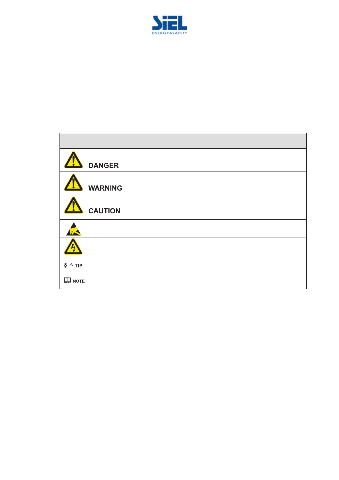
Symbol Conventions
The manual quotes the safety symbols, these symbols used to prompt users to comply with safety
matters during installation, operation and maintenance. Safety symbol meaning as follows.
Symbol
Description
Alerts you to a high
-
risk hazard that could, if not avoided, result in
serious injury or death.
Alerts you to a medium or low risk hazard that could, if not avoided,
result in moderate or minor injury.
Alerts
you to a potentially hazardous situation that could, if not
avoided, result in equipment damage, data loss, performance
deterioration, or unanticipated results.
Anti
-static prompting.
Be care electric shock prompting
.
Provides a tip that may
help you solve a problem or save time.
Provides
additional
information to emphasize or supplement important
points in the main text.

IV430E REV. 00 Issued: 2020/06/03 User Manual SOLEIL SRT 1.5-6k 1ph Pag. 6 of 56 +FR
Contents
1 Safety Description.........................................................................................................................9
1.1 Safety Announcements..................................................................................................................................... 9
1.1.1 Safety Instructions .................................................................................................................................. 9
1.1.2 Protection for PV Array ........................................................................................................................ 11
1.1.3 Anti-Static Protection............................................................................................................................ 11
1.1.4 Grounding Requirements ...................................................................................................................... 11
1.1.5 Moisture-proof Protection..................................................................................................................... 12
1.1.6 Safety Warning Label Setting ............................................................................................................... 12
1.1.7 Electrical Connection............................................................................................................................ 12
1.1.8 Measure with voltage present................................................................................................................ 13
1.2 Requirements for Operator............................................................................................................................. 13
1.3 Environment Requirements............................................................................................................................ 13
2 Overview.......................................................................................................................................15
2.1 Product Intro................................................................................................................................................... 15
2.1.1 Model Meaning..................................................................................................................................... 15
2.1.2 Product Features.................................................................................................................................... 15
2.2 Appearance and Structure............................................................................................................................... 16
2.2.1 Operation Panel..................................................................................................................................... 16
2.2.2 External Terminal Illustration ............................................................................................................... 17
2.3 Work Principle................................................................................................................................................ 18
3 Installation Guide .......................................................................................................................20
3.1 Installation Process......................................................................................................................................... 20
3.2 Installation Preparation .................................................................................................................................. 20
3.2.1 Tools...................................................................................................................................................... 20
3.2.2 Installation Environment....................................................................................................................... 21
3.2.3 Installation Space .................................................................................................................................. 22
3.2.4 Installation Way .................................................................................................................................... 23
3.3 Transportation and unpacking ........................................................................................................................ 23

IV430E REV. 00 Issued: 2020/06/03 User Manual SOLEIL SRT 1.5-6k 1ph Pag. 7 of 56 +FR
3.3.1 Transportation ....................................................................................................................................... 23
3.3.2 Unpacking and Checking ...................................................................................................................... 23
3.4 Installation...................................................................................................................................................... 24
3.5 Electrical Connection ..................................................................................................................................... 28
3.5.1 Wire Requirement ................................................................................................................................. 28
3.5.2 External Grounding Connection ........................................................................................................... 29
3.5.3 DC Input (PV) Connection ................................................................................................................... 29
3.5.4 AC Output (GRID) Connection ............................................................................................................ 32
3.5.5 WIFI/GPRS Connection........................................................................................................................ 34
3.5.6 Communication Port Connection (Optional) ........................................................................................ 35
3.6 Check the Installation..................................................................................................................................... 36
4 LCD Operation ............................................................................................................................37
4.1 First Startup.................................................................................................................................................... 37
4.2 Main Page ...................................................................................................................................................... 37
4.3 Main Menu Page ............................................................................................................................................ 38
4.3.1 Running Information............................................................................................................................. 39
4.3.2 Power Query ......................................................................................................................................... 39
4.3.3 Record Query ........................................................................................................................................ 40
4.3.4 System Setting ...................................................................................................................................... 42
4.3.5 System Information............................................................................................................................... 44
5 Startup and shutdown................................................................................................................46
5.1 Startup ............................................................................................................................................................ 46
5.2 Shutdown ....................................................................................................................................................... 46
6 Maintenance and Troubleshooting .........................................................................................47
6.1 Maintenance ................................................................................................................................................... 47
6.2 Troubleshooting.............................................................................................................................................. 47
7 Package, Transportation and Storage......................................................................................50
7.1 Package .......................................................................................................................................................... 50
7.2 Transportation ................................................................................................................................................ 50

IV430E REV. 00 Issued: 2020/06/03 User Manual SOLEIL SRT 1.5-6k 1ph Pag. 8 of 56 +FR
7.3 Storage ........................................................................................................................................................... 50
8 Technical Specifications ............................................................................................................51
9 Reference Standards ...................................................................................................................54

IV430E REV. 00 Issued: 2020/06/03 User Manual SOLEIL SRT 1.5-6k 1ph Pag. 9 of 56 +FR
1 Safety Description
This chapter introduces the safety announcements. Please read this user manual carefully prior to
installing the inverter. It provides important information on safe and efficient installation.
1.1 Safety Announcements
Before operation, please read the announcements and operation instructions in this part, which is to
avoid accident.
The DANGER, WARNING, CAUTION in the manual, are not all the safety announcements that
must be abided by, they are just the supplement of the safety announcements during operating.
Company does not undertake the responsibility caused by violating common safety operation
requirements or the safety standard of design, manufacture and use.
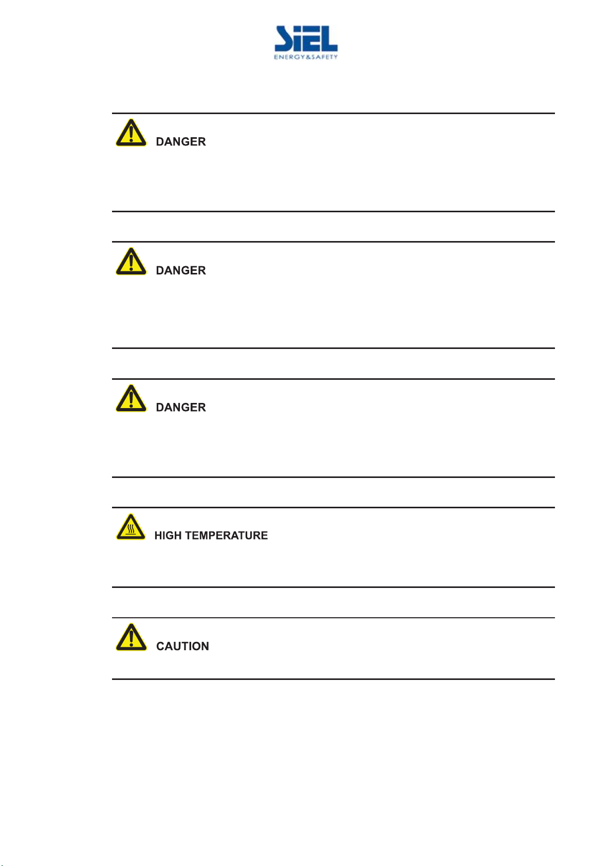
1.1.1 Safety Instructions
It is prohibited touching any terminal or conductor that connected with grid circuit, or, it may cause
deadly danger.
IV430E REV. 00 Issued: 2020/06/03 User Manual SOLEIL SRT 1.5-6k 1ph Pag. 10 of 56 +FR
There is no operational part inside the inverter. Please do not open the crust of the inverter by
yourself, or it may cause electric shock. The inverter damage caused by illegal operation is out of the
guarantee range.
The damaged device or device fault may cause electric shock or firing!
lBefore operating, please inspect the device and see if there is any damage or exist other danger.
lCheck if the external devices or circuit connection is safe.
Before checking or maintenance, if the DC side and AC side is power down just now, it is necessary
to wait for 5 minutes to ensure the inner device is completely discharged, and then the operation can
be performed.
The surface temperature of the inverter may reach to 75ȭ. During running, please don't touch the
surface to avoid scald.
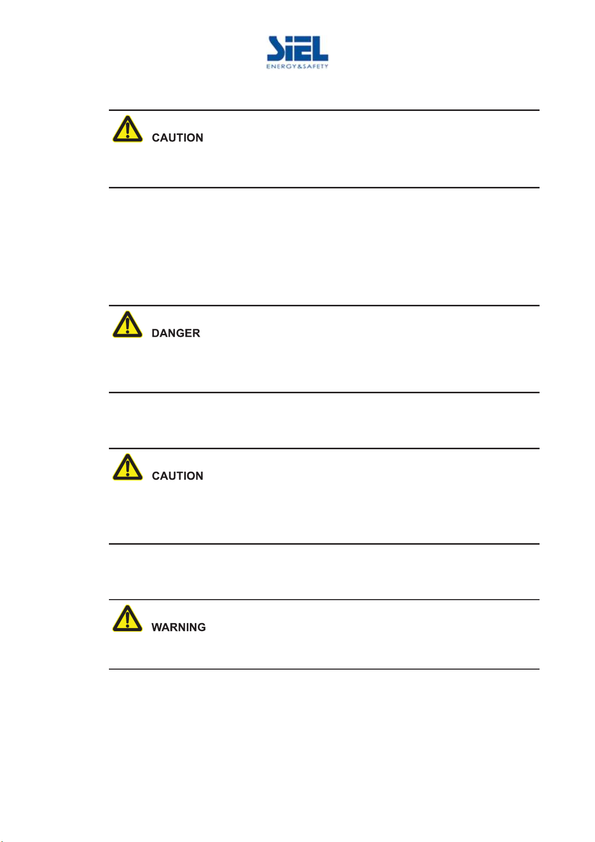
No liquid or other objects are allowed to enter the inverter.
IV430E REV. 00 Issued: 2020/06/03 User Manual SOLEIL SRT 1.5-6k 1ph Pag. 11 of 56 +FR
In case fire, please use dry power fire extinguisher. If using liquid fire extinguisher, it may cause
electric shock.
1.1.2 Protection for PV Array
When install the PV array in the daytime, use light-proof material to cover the PV array, or, under the
sunshine, the PV array will generate high voltage. Once touch the PV array by accident, it may cause
electric shock or endanger human life.
There is deadly high voltage between the positive and negative of the PV array.
During installing, ensure that the connection between inverter and PV array is completely
disconnected and set warning marks at the disconnection to avoid reconnecting by accident.
1.1.3 Anti-Static Protection
The static electricity generated by human bodies may damage the electrostatic-sensitive components
on boards. Before touching the sensitive component, please wear anti-static rings and well connect
the other end of the anti-static rings to ground.
1.1.4 Grounding Requirements
High leakage risk! The inverter must be grounded before electrical connection. The ground terminal
must be connected to earth.
lWhen installing, connect the grounding wire first; when dismantling, the grounding wire must be
removed at last.
lIt is prohibited to damage the grounding conductor.
lThe device must be connected with protection earthing permanently. Before operating, please
check the electric connection and ensure the device has been connected to earth reliably.
IV430E REV. 00 Issued: 2020/06/03 User Manual SOLEIL SRT 1.5-6k 1ph Pag. 12 of 56 +FR
1.1.5 Moisture-proof Protection
Moisture incursion may cause the inverter damage!
For normal use of the energy-storage converter, please comply with the following items.
lIf the atmosphere humidity larger than 95%, please do not open the inverter.
lOn overcast or rainy or moist condition, avoid opening the panel to maintain or do other
operation.
1.1.6 Safety Warning Label Setting
In order to avoid accident for unwanted person gets close to inverter or makes improper operation, it
should observe the following requirements when perform installation, daily maintenance or repair.
lSet warning labels at the front end and back end of the inverter to avoid wrongly close and even
cause accident.
lSet warning label board or safety warning area to avoid irrelevant person entering and cause
human injury or device damage.
1.1.7 Electrical Connection
The electrical connection must be done on the basis of the illustration and electrical wiring principle
mentioned in this manual.
The PV array and grid level, frequency, etc. must accord with the inverter’s specification.
The grid-connected generation must be allowed by local power supply department and operate by
professionals.
All the electrical connection must accord with the electrical installation standard of local nation and
district.
IV430E REV. 00 Issued: 2020/06/03 User Manual SOLEIL SRT 1.5-6k 1ph Pag. 13 of 56 +FR
1.1.8 Measure with voltage present
There is dangerous high voltage, contacting by accident may lead to deadly danger. So, when
measure with electricity, it is necessary to do the protection (such as wear insulated gloves, etc.)
The measure meter must accord with the following requirements.
lThe range and sue condition of the measure meter should conform to the site requirements.
lEnsure that connection of the measure meter is proper and normative, which is to avoid the
danger of electric arc, etc.
1.2 Requirements for Operator
The related operation and wiring for the inverter should be performed by qualified professionals and
ensure the electric installation accord with the electricity installation standards.
The installation and maintenance man should be trained and know each safety announcements and
get the right operation method, and then, the installation, operation and maintenance can be done.
lThe operator should be familiar with the constitution and work principle of the whole PV
grid-connected generation system.
lThe operator must be acquainted with the related standards of local nation and region.
1.3 Environment Requirements
Avoid the inverter suffering directly sunshine, rain or snow to prolong the service life (detail please
see 3.2.2 ). If the installation environment does not meet the requirement, the guarantee time may be
influenced.

IV430E REV. 00 Issued: 2020/06/03 User Manual SOLEIL SRT 1.5-6k 1ph Pag. 14 of 56 +FR
The used environment may influence the service life and reliability of the inverter. So, please avoid
using the inverter in the following environment for long time.
lThe place where beyond the specification (normal work temperature: -30ć60ć, relative
humidity: 0%-95%).
lThe place where has vibration or easy impacted.
lThe place where has dust, corrosive material, salty or flammable gas.
lThe place where without good ventilation or closed.
IV430E REV. 00 Issued: 2020/06/03 User Manual SOLEIL SRT 1.5-6k 1ph Pag. 15 of 56 +FR
2 Overview
This chapter mainly introduces the inverter features, appearance, operation panel, work principle, etc.
2.1 Product Intro
The inverter is the device that converts DC energy from solar array into AC energy and then
feedbacks to power grid. It is suitable for home and commercial roof PV generation system and
distributed PV generation system. Generally, the system consists of PV arrays, PV Grid-Connected
Inverter and power distribution system, as shown in Figure2-1.
Inverter Grid
PV
arrays
Figure2-1 Compose of PV generation system
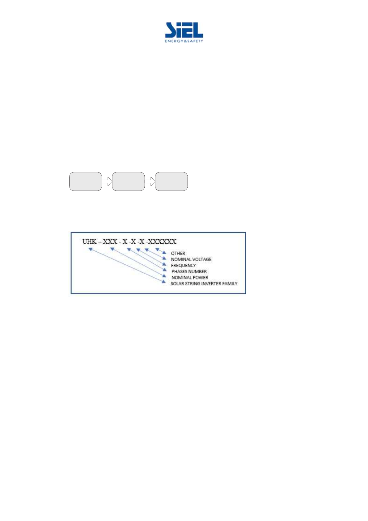
2.1.1 Model Meaning
Figure2-2 Model meaning illustration
As shown in Errore. L'origine riferimento non è stata trovata., "UHK" means that the product is S
iel Soleil SRT series PV gird-tied invert.
2.1.2 Product Features
lEfficiently power generation: adopt efficient HERIC inverter topology and advanced completely
digitized control technology.
lSafe and reliable: adopt aluminum alloy to diecast the outer case, so that the inverter can work in
a widely temperature range.
lSmart managing: smart cloud platform monitoring and APP monitor. The inverter supports
RS485, GPRS and WIFI communication, and can be updated online.
lGreen and friendly: small size, easy installation and use, air cooling, low noise.
lBetter adaptability: with better grid adaptability, wide reactive power adjusting range.

IV430E REV. 00 Issued: 2020/06/03 User Manual SOLEIL SRT 1.5-6k 1ph Pag. 16 of 56 +FR
2.2 Appearance and Structure
The appearance of the inverter is as shown in Figure2-3.
Figure2-3 Appearance of the inverter
2.2.1 Operation Panel
Figure2-4 Operation panel
Table2-1 Illustration of the operation panel
NO
Symbol Illustration Remarks
1
- LCD
lShows the inverter status and information.
lShows the service and operation information
lShows the alarm information and fault.
2
Power indicator
(green)
On: inverter is in grid
-connected status.
F
licker: PV power is normal
3
Alarm indicator (red)
On: inverter fault.
Off: there is no fault.
4
ESC button
Short press: move the cursor upward or increase the setting value.
L
ong press: back to previous menu or cancel the current
command.
5
ENT button
Short press: move the cursor downward or decrease the setting
value.
L
ong press: enter sub menu or confirm the current command.

IV430E REV. 00 Issued: 2020/06/03 User Manual SOLEIL SRT 1.5-6k 1ph Pag. 17 of 56 +FR
Short press: less than 1s, Long press: more than 1s.
2.2.2 External Terminal Illustration
The external terminals are all located in the bottom of the inverter, including PV input, AC output,
communication port and DC switch, etc, as shown in Figure2-5.
Figure2-5 Bottom view
Table2-2 Terminals illustration
NO.
Terminal
Illustration Remarks
1
DC SWITCH
DC transform switch
Optional
2
PV
+
DC input terminal
For SOLEIL SRT1.5K and SOLEIL SRT2
K,
there are 1 pair of DC terminals (+,-),
for other
models, there are 2 pairs of DC terminals (+,-)
-
3
WIFI/GPRS
WIFI/GPRS port
I
t is used to monitor the running status of the
inverter.
4
COM.
Connect with METER
Optional
5
GRID
AC output terminal
It is used to connect with grid.
6
- Lock It needs to provide by customer.
7
G
rounding port
External grounding port
When the DC SWITCH and COM. is not selected, the corresponding port is filled with a waterproof
plug.
IV430E REV. 00 Issued: 2020/06/03 User Manual SOLEIL SRT 1.5-6k 1ph Pag. 18 of 56 +FR
DC switch
DC switch (as shown in Figure2-5,1) is the connection switch of inverter and PV array. When the
inverter works normally, the DC switch must be ON. During installation and wiring, the DC switch
must be OFF. Before maintenance, the DC switch must be OFF for 20 minutes, and measure the
voltage of DC busbar by multimeter, only when the voltage less than 10V, the maintenance can be
done.
when maintenance or wiring, the DC switch must be disconnected.
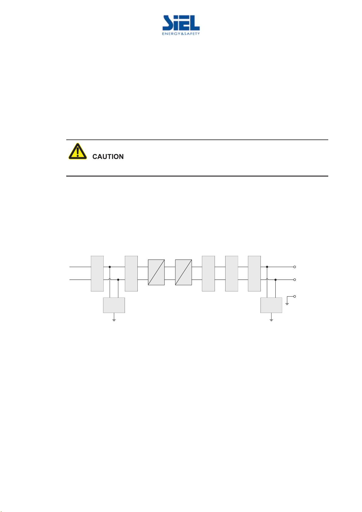
2.3 Work Principle
The inverter connects with PV array input and tracks the maximum power point of the PV array, and
then converts the DC power into single-phase AC power by inverter circuit. It also provides surge
protection at DC and AC side, as shown inFigure2-6, Figure2-7.
DC switch
PV+
PV-
Input filter
optional
DC
SPD
DC
DC
Boost
circuit
DC
AC
Inverter
circuit
LC filter
Output relay
Output filter
L
NGRID
AC
SPD
PE
Figure2-6 Work principle diagram of SOLEIL SRT 1.5K, SOLEIL SRT 2K

IV430E REV. 00 Issued: 2020/06/03 User Manual SOLEIL SRT 1.5-6k 1ph Pag. 19 of 56 +FR
DC switch
+
-
Input filter
Optional
DC
SPD
DC
DC
Boost
circuit 1
DC
AC
Inverter
circuit
LC filter
Output relay
Output filter
L
NGRID
AC
SPD
PE
PV1
+
-
Input filter
DC
SPD
Boost
circuit 2
PV2
DC
DC
Figure2-7 Work principle diagram of SOLEIL SRT 3K, SOLEIL SRT 3.6K, SOLEIL SRT 4K, SOLEIL
SRT 4.6K, SOLEIL SRT 5K, SOLEIL SRT 6K

IV430E REV. 00 Issued: 2020/06/03 User Manual SOLEIL SRT 1.5-6k 1ph Pag. 20 of 56 +FR
3 Installation Guide
This chapter introduces the installation of the inverter, including installation process, installation
preparation, transportation and unpacking, installation procedure, electrical connection and checking,
etc.
3.1 Installation Process
Start
Install the
inverter
Electrical
connection
Check the
installation
End
Installation
preparation
Figure3-1 Installation process
3.2 Installation Preparation
3.2.1 Tools
Tools
Table of contents
Other Siel Inverter manuals


