Siel Soleil SPX Series User manual

Soleil SPX Series (200K-250K) 3ph
String PV Grid-tied Inverter
User Manual


IV431E REV. 00 Issued: 2020/11/16 User Manual Soleil SPX 200K-250K Pag. 1 of 76 +FR
Notice
The purchased products, services and features are stipulated by the contract made between SIEL and the customer.
All or part of the products, services and features described in this document may not be within the purchase scope
or the usage scope. Unless otherwise specification in the contract, all statements, information, and recommendations
in this document are provided “AS IS” without warranties, guarantees or representations of any kind, either express
or implied.
The information in this document is subject to change without notice. Every effort has been made in the preparation
of this document to ensure accuracy of the contents, but all statements, information, and recommendations in this
document do not constitute a warranty of any kind, express or implied.

IV431E REV. 00 Issued: 2020/11/16 User Manual Soleil SPX 200K-250K Pag. 2 of 76 +FR
Foreword
Summaries
Thank you for choosing the SPX series (200K-250K) string PV grid-tied inverter (hereinafter referred
to as inverter)!
This document gives a description of the inverter, including appearance, features, working principles,
installation, electrical connection, operation, maintenance and storage, etc.
Please save the manual after reading, in order to consult in the future.
The figures in this manual are just for reference, for details please see the actual product.
Applicable Model
lSoleil SPX 200K
lSoleil SPX 225K
lSoleil SPX 250K
IV431E REV. 00 Issued: 2020/11/16 User Manual Soleil SPX 200K-250K Pag. 3 of 76 +FR
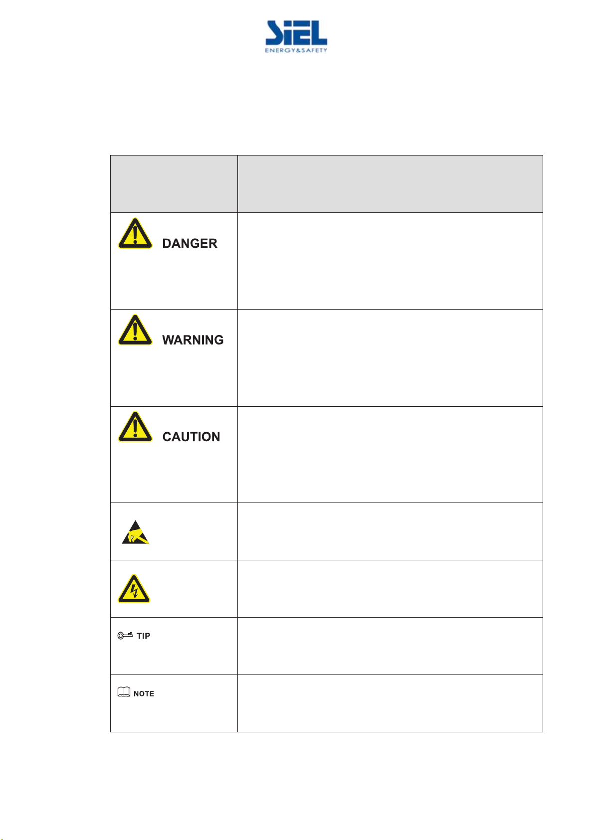
Symbol Conventions
The manual quotes the safety symbols, these symbols used to prompt users to comply with safety
matters during installation, operation and maintenance. Safety symbol meaning as follows.
Symbol
Description
Alerts you to a high
-
risk hazard that could, if not avoided, result in
serious injury or death.
Alerts you to a medium or low risk hazard that could, if not avoided,
result in moderate or minor injury.
Alerts
you to a potentially hazardous situation that could, if not
avoided, result in equipment damage, data loss, performance
deterioration, or unanticipated results.
Anti
-static prompting.
Be care
electric shock prompting.
Provides a tip that may help you solve a problem or save time.
Provides
additional
information to emphasize or supplement important
points in the main text.

IV431E REV. 00 Issued: 2020/11/16 User Manual Soleil SPX 200K-250K Pag. 4 of 76 +FR
Contents
1 Safety Description.........................................................................................................................7
1.1 Safety Announcements..................................................................................................................................... 7
1.1.1 Use Announcements................................................................................................................................ 7
1.1.2 PV String Protection ............................................................................................................................... 8
1.1.3 ESD Protection........................................................................................................................................ 9
1.1.4 Grounding Requirements ........................................................................................................................ 9
1.1.5 Moistureproof Protection ........................................................................................................................ 9
1.1.6 Warning Mark Setting ........................................................................................................................... 10
1.1.7 Electrical Connection............................................................................................................................ 10
1.1.8 Measurement Under Operation ............................................................................................................. 10
1.2 Operator Requirements .................................................................................................................................. 11
2 Overview.......................................................................................................................................12
2.1 Product Intro................................................................................................................................................... 12
2.1.1 Features................................................................................................................................................. 13
2.1.2 Model Meaning..................................................................................................................................... 13
2.2 Apperance and Structure ................................................................................................................................ 13
2.2.1 Apperance ............................................................................................................................................. 13
2.2.2 Operation Panel..................................................................................................................................... 14
2.2.3 Bottom Layout ...................................................................................................................................... 14
2.2.4 Size........................................................................................................................................................ 16
2.3 Working Principle........................................................................................................................................... 16
2.4 Communication .............................................................................................................................................. 16
2.4.1 Ethernet Communication ...................................................................................................................... 16
2.4.2 RS485 Communication ......................................................................................................................... 17
2.4.3 PLC Communication (Optional) ........................................................................................................... 18
2.4.4 PID Function (Optional) ....................................................................................................................... 19
3 Installation....................................................................................................................................21
3.1 Installation Process......................................................................................................................................... 21

IV431E REV. 00 Issued: 2020/11/16 User Manual Soleil SPX 200K-250K Pag. 5 of 76 +FR
3.2 Installation Tools ............................................................................................................................................ 22
3.3 Selection of Installation Site .......................................................................................................................... 23
3.3.1 Installation Environment....................................................................................................................... 23
3.3.2 Installation Clearance............................................................................................................................ 24
3.3.3 Requirements for Installation Carrier.................................................................................................... 25
3.3.4 Installation Method ............................................................................................................................... 25
3.4 Transporting, Unpacking and Checking ......................................................................................................... 26
3.4.1 Transporting .......................................................................................................................................... 26
3.4.2 Unpacking and Checking ...................................................................................................................... 28
3.5 Inverter Installation ........................................................................................................................................ 28
3.5.1 Bracket Installation ............................................................................................................................... 28
3.5.2 Wall Mounting ...................................................................................................................................... 32
3.6 Electrical Connection ..................................................................................................................................... 36
3.6.1 Safety Announcements.......................................................................................................................... 36
3.6.2 Requirements for Wire .......................................................................................................................... 36
3.6.3 External Grounding Connection ........................................................................................................... 37
3.6.4 AC Output Wiring ................................................................................................................................. 39
3.6.5 Internal Grounding Connection............................................................................................................. 44
3.6.6 PV String Input Wiring ......................................................................................................................... 44
3.6.7 WIFI/GPRS Communication Connection (Optional) ........................................................................... 49
3.6.8 COM. Communication Connection ...................................................................................................... 50
3.7 Check the Installation..................................................................................................................................... 53
4 Startup and Shutdown ...............................................................................................................54
4.1 Check Before Startup ..................................................................................................................................... 54
4.2 Start Inverter................................................................................................................................................... 54
4.3 Shut Down Inverter ........................................................................................................................................ 55
5 Maintenance and Troubleshooting .........................................................................................56
5.1 Maintenance ................................................................................................................................................... 56
5.1.1 Maintenance Details and Period............................................................................................................ 56
5.1.2 Maintenance Guide ............................................................................................................................... 57
5.2 Troubleshooting.............................................................................................................................................. 59

IV431E REV. 00 Issued: 2020/11/16 User Manual Soleil SPX 200K-250K Pag. 6 of 76 +FR
6 Stop Running, Dismantle, Discard Inverter..........................................................................62
6.1 Stop Running.................................................................................................................................................. 62
6.2 Dismantle the Inverter.................................................................................................................................... 62
6.3 Discard the Inverter........................................................................................................................................ 63
7 Package, Transportation, Storage.............................................................................................64
7.1 Package .......................................................................................................................................................... 64
7.2 Transportation ................................................................................................................................................ 64
7.3 Storage ........................................................................................................................................................... 64
8 Technical Specifications ............................................................................................................65
9 Reference Standards...................................................................................................................72
10 Quality Assurance.....................................................................................................................73

IV431E REV. 00 Issued: 2020/11/16 User Manual Soleil SPX 200K-250K Pag. 7 of 76 +FR
1 Safety Description
This chapter mainly describes the safety announcements. Prior to performing any work on the device,
please read the user manual carefully, follow the operation and installation instructions and observe all
danger, warning and safety information.
1.1 Safety Announcements
This section mainly describes the safety announcements when operation and maintenance. For details,
please refer to safety description in relevant chapters.
Before operation, please read the announcements and operation instructions in this section carefully to
avoid accident.
The promptings in the user manual, such as "Danger", "Warning", "Caution", etc. don't include all
safety announcements. They are just only the supplement of safety announcements when operation.
Any device damage caused by violating the general safety operation requirements or safety standards
of design, production, and usage will be out of SIEL's warranty range.
1.1.1 Use Announcements
Don't touch terminals or conductors that connected with grid to avoid lethal riskʽ
IV431E REV. 00 Issued: 2020/11/16 User Manual Soleil SPX 200K-250K Pag. 8 of 76 +FR
There is no operational part inside device. Please do not open the crust of device by yourself, or it may
cause electric shock. The device damage caused by illegal operation is out of the guarantee range
After disconnect the input and output of the inverter, there still has residual energy in the storage
capacitor, which may cause electric shock. Do not perform the maintenance until all power sources are
switched off for 30 minutes.
Please do not put fingers or tools into the rotating fans to avoid human injury or device damage.
The surface temperature of the inverter may reach to 75ȭ. During running, please don't touch the
surface to avoid scald.
No liquid or other objects are allowed to enter the inverter, or, it may cause inverter damage.
In case of fire, please use dry power fire extinguisher. If using liquid fire extinguisher, it may cause
electric shock.
1.1.2 PV String Protection
When install PV string in daytime, it necessary to cover the PV string by light-proof material, or the
PV string will generate high voltage under sunshine. If touching PV string accidently, it may cause
electric shock or human injury!
IV431E REV. 00 Issued: 2020/11/16 User Manual Soleil SPX 200K-250K Pag. 9 of 76 +FR
There exists dangerous voltage between the positive and negative of PV string!
When installing the device, make sure that the connection between inverter and PV string has been
disconnected completely. And set warning mark in the disconnected position to avoid reconnecting.
1.1.3 ESD Protection
To prevent human electrostatic damaging sensitive components (such as circuit board), make sure that
you wear a anti-static wrist strap before touching sensitive components, and the other end is well
grounded.
1.1.4 Grounding Requirements
High leakage risk! The inverter must be grounded before wiring. The grounding terminal must be
connected to ground, or, there will be the risk of electric shock when touching the inverter.
lWhen installing, the inverter must be grounded first. When dismantling, the grounding wire must
be removed at last;
lDon't damage the grounding conductor;
lThe inverter must be connected to protection grounding permanently.
lBefore operation, check the electrical connection to ensure the inverter is grounded reliably.
1.1.5 Moistureproof Protection
Moisture invasion may cause inverter damage!
Observe the following items to ensure the inverter works normally.
lWhen the air humidity is more than 95%, don't open the door of the inverter;
lIn the wet or damp weather, don't open the door of the inverter to maintain or repair.

IV431E REV. 00 Issued: 2020/11/16 User Manual Soleil SPX 200K-250K Pag. 10 of 76 +FR
1.1.6 Warning Mark Setting
In order to avoid accident for unwanted person gets close to the inverter or makes improper operation,
observe the following requirements while installing, maintaining or repairing.
lSet warning marks where the switches are to avoid switching them on improperly.
lSet warning signs or safety warning belt in the operation area, which is to avoid human injury or
device damage.
1.1.7 Electrical Connection
Electrical connection must be performed according to the description in the user manual and the
electrical circuit schematic.
The configuration of PV string, grid level, grid frequency, etc. must meet the technical requirements of
inverter.
Grid-tied generation should be allowed by the local power supply department and the related operation
should be performed by professionals.
All electrical connection must meet the related country and district standard.
1.1.8 Measurement Under Operation
There exists high voltage in the device. If touching device accidently, it may cause electric shock. So,
when perform measurement under operation, it must take protection measure (such as wear insulated
gloves, etc.)
The measuring device must meet the following requirements:
lThe range and operation requirements of measuring device meets the site requirements;
lThe connections for measuring device should be correct and standard to avoid arcing.

IV431E REV. 00 Issued: 2020/11/16 User Manual Soleil SPX 200K-250K Pag. 11 of 76 +FR
1.2 Operator Requirements
The operation and wiring for inverter should be performed by qualified person, which is to ensure that
the electrical connection meets the related standards.
The professional technicist must meet the following requirements:
lBe trained strictly and understand all safety announcements and master correct operations.
lFully familiar with the structure and working principle of the whole PV grid-tied generation system.
lKnow well about the related standards of local country and district.
IV431E REV. 00 Issued: 2020/11/16 User Manual Soleil SPX 200K-250K Pag. 12 of 76 +FR
2 Overview
This chapter mainly describes product appearance, structure, working principle and communication
method, etc.
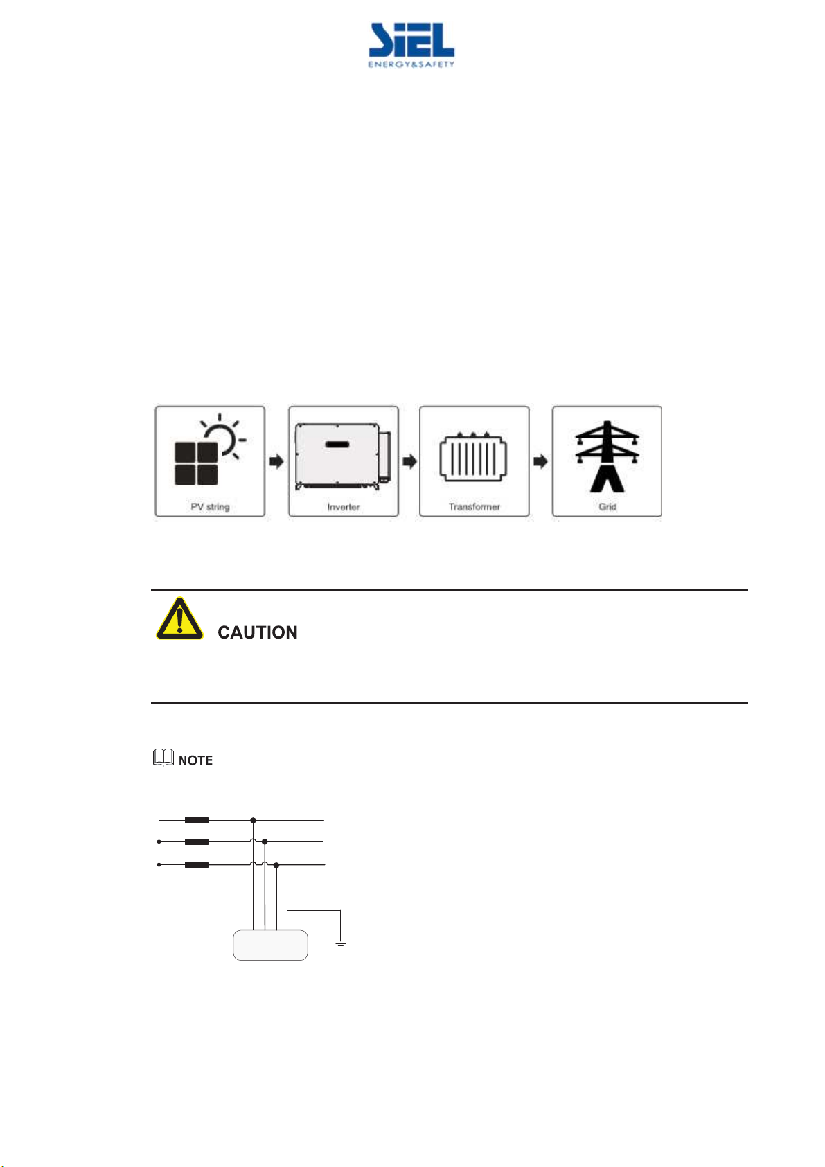
2.1 Product Intro
The inverter converts the DC energy from PV string into AC energy and then feedbacks to power grid,
which is suitable for the large power station grid-tied system. The PV grid-tied generation system
consists of PV string, PV grid-tied inverter, transformer and power distribution system, as shown
Figure2-1.
Figure2-1 PV grid-tied generation system
PV grid-tied power generation needs to obtain the permission of local power supply department and
performed by professionals.
The grid form supported by the inverter is shown in Figure2-2.
Inverter
Transformer
IT
PE
L1
L2
L3
Figure2-2 Grid form

IV431E REV. 00 Issued: 2020/11/16 User Manual Soleil SPX 200K-250K Pag. 13 of 76 +FR
2.1.1 Features
lInnovated three level design, with high transition efficiency.
lSupport PLC communication, night SVG function, which satisfies the requirement of grid
scheduling.
lThe reactive power is adjustable, the range of power factor is -0.8(lag)+0.8(ahead).
lSmart I-V scanning, fault wave capture, remote online update function.
lPerfect protection functions: island protection, high/low voltage ride through, reverse DC
connection protection, AC short circuit protection, leakage current protection, surge protection, etc.
2.1.2 Model Meaning
Figure2-3 Model meaning
As shown in Figure2-3 "UHK" means that the product is SIEL Soleil SPX series PV inverter.
2.2 Apperance and Structure
2.2.1 Apperance
The appearance of SPX series string PV grid-tied inverter is as shown in Figure2-4.
Figure2-4 Appearance

IV431E REV. 00 Issued: 2020/11/16 User Manual Soleil SPX 200K-250K Pag. 14 of 76 +FR
2.2.2 Operation Panel
There are 4 status indicators on the front panel of the inverter, which can indicate the current working
status of the inverter. The status of each indicator is shown in Table2-1.
Figure2-5 Operation panel
Table2-1 Indicator status illustration
NO.
Mark
Color
Meaning Status illustration
1
Green
PV string
indicator
ON:
At least a group of PV string
has been
connected.
F
licker: Night SVG mode grid-tied status.
OFF: All
PV strings are disconnected.
2
Green
Grid indicator
ON: Grid
-tied status.
F
licker
: Inverter stay in decrease rated power output
status
.
OFF: No grid
-tied status.
3
Green
WIFI/GPRS
indicator
ON: WIFI/ GPRS has been connected
.
OFF: WIFI/ GPRS has been disconnected
.
4
Red
Fault indicator
ON: The inverter has alarm.
2.2.3 Bottom Layout
The inverter's bottom layout is shown as Figure2-6.

IV431E REV. 00 Issued: 2020/11/16 User Manual Soleil SPX 200K-250K Pag. 15 of 76 +FR
Figure2-6 Bottom layout
Table2-2 Mark description
NO.
Mark Name Remarks
1
MPPT n +/MPPT n -
Input
PV string
terminal
Used to connect
PV string input.
2
DC SWITCH
DC switch
It is the c
onnection switch
between
inverter and
PV string. E
ach DC switch
controls the
PV string
input terminals of
marked area.
3
BREATHER
VALVE
Breath
er valve
Used to
balance
the pressure difference
between inside and outside of the
inverter
.
4
WIFI/GPRS
WIFI/GPRS
interface
Used to
WIFI/GPRS connection
and
communication
5
AC
OUTPUT
AC
output wiring
Used to connect the wire of AC output.
6
COM.
Communication wiring
Used to connect the communication wire
of
RS485 or Ethernet.
7
8
Internal
grounding
For internal ground
ing.
9
External ground
ing
terminal
F
or the grounding of the inverter.
DC Switch
The DC switch (the position is shown as 2 in Figure2-6) is the connection switch between the inverter
and the PV string, when necessary, it can safely disconnect the connection of the inverter and the PV
string. In order to ensure the safety of the operator, make sure that the DC switch is turned off under
the following conditions:
lWhen installing and wiring, the DC switch must be placed to OFF position.

IV431E REV. 00 Issued: 2020/11/16 User Manual Soleil SPX 200K-250K Pag. 16 of 76 +FR
lWhen checking and repairing, place the DC switch to OFF position and wait for 30 minutes. Use
a multimeter to measure the DC bus voltage inside the inverter, only when the voltage lower than
10V, you can perform repair work.
2.2.4 Size
Figure2-7 Size (unit: mm)
2.3 Working Principle
The PV string input is connected to the inverter, and the maximum power point for the PV string is
tracked through the internal 12 groups of MPPT circuits to achieve the maximum power output of the
PV string, and then the conversion of DC power to three-phase AC power is realized through the
inverter circuit, as shown in Figure2-8.
Output
EMI filter
Relays
SPD
CHCT
HCT
HCT
(–)
( + )
(–)
( + )
(–)
( + )
MPPT1
C
(–)
( + )
PWM
+
–
GND
DC/DC1
DC/DC12
Ă
L1
L2
L3
PE
Input
EMI filter
ĂĂ
ĂĂ
SPD
GND
GND
DC switch
L1 L2 L3
MPPT12
Figure2-8 Working principle diagram
2.4 Communication
The inverter has multiple communication methods, including Ethernet communication, RS485
communication, WIFI/GPRS communication (optional), and PLC communication (optional). Users
can easily obtain the current operation data of the inverter.
2.4.1 Ethernet Communication
Ethernet communication (the interface is shown in Figure2-9) is mainly used for local area network
monitoring, which can realize the background remote monitoring.
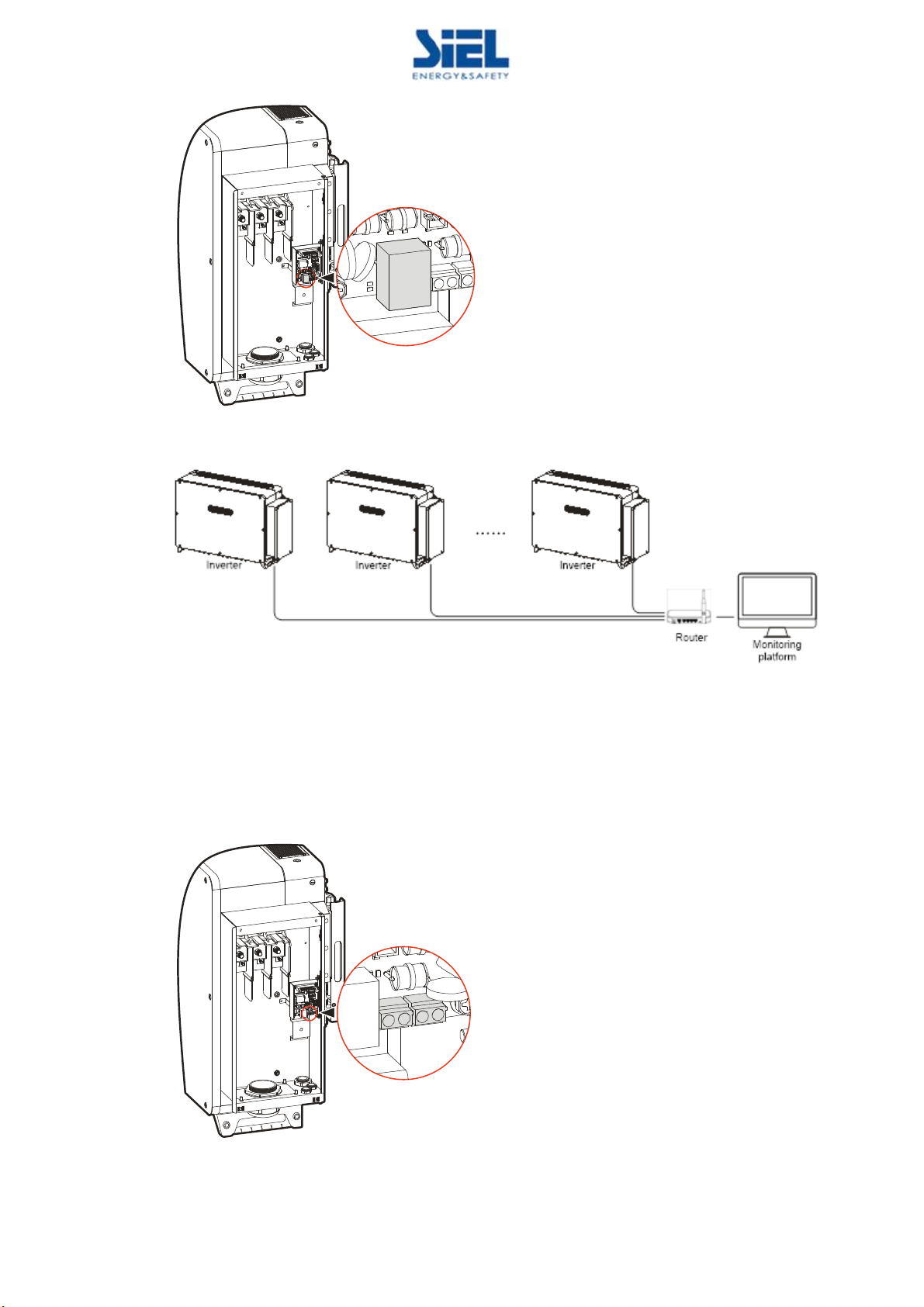
IV431E REV. 00 Issued: 2020/11/16 User Manual Soleil SPX 200K-250K Pag. 17 of 76 +FR
Figure2-9 Ethernet communication interface diagram
Figure2-10 Ethernet monitoring (multiple inverters)
2.4.2 RS485 Communication
RS485 communication (the interface is shown in Figure2-11) is mainly used for local area network
monitoring, which can realize the background remote monitoring.
Figure2-11 RS485communication interface diagram
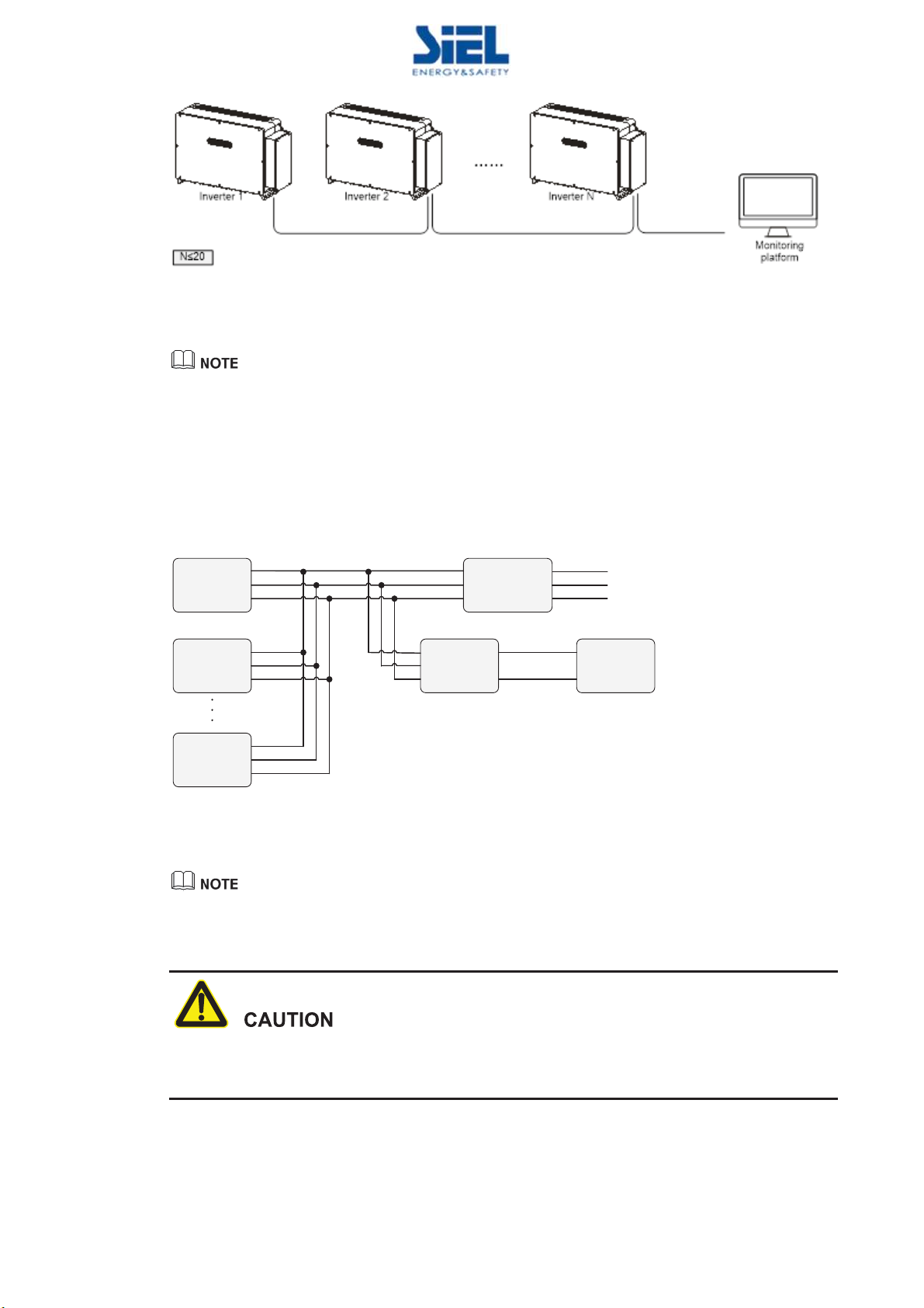
IV431E REV. 00 Issued: 2020/11/16 User Manual Soleil SPX 200K-250K Pag. 18 of 76 +FR
Figure2-12 RS485 communication (multiple inverters)
When there is only one inverter communicates via RS485, choose one of the two communication
interfaces to connect.
2.4.3 PLC Communication (Optional)
If the inverter is equipped with PLC communication, sub-array controller needs to be configured. The
output end of the inverter must pass through the isolation transformer and then be connected to grid,
as shown in Figure 2-13.
Inverter 1
Inverter 2 Sub-array
controller PC
Isolation
transformer Grid
RS485
Inverter N
Figure2-13 PLC communication connection
The setting of PLC communication address is the same as that of RS485, details please see 3.6.8 COM.
Communication Connection.
If PLC communication is configured, the AC cables can only be multi-core cable, single-core cable
cannot be used.
This manual suits for next models
3
Table of contents
Other Siel Inverter manuals


Popular Inverter manuals by other brands


ZCS
ZCS 3K-6K TLM LITE Series user manual

MPP Solar
MPP Solar LVX 6048 user manual

CUSTOM POWER DESIGN
CUSTOM POWER DESIGN Handy Mains Series quick start guide

Sunrioy
Sunrioy SR-300-S user manual

Fischer Panda
Fischer Panda Panda AGT/DC 10000 PMS Operation manual

Ginlong
Ginlong GCI-H-US-HY Installation and operation manual