TBB Kinergier Pro Series User manual
Kinergier pro bi-directional inverter User Manual
TBB Power Co., Ltd
Kinergier Pro series
Bi-directional inverter
Version:V1.0
Date: Mar.2019

Kinergier pro bi-directional inverter User Manual
TBB Power Co., Ltd
Kinergier pro bi-directional inverter User Manual
TBB Power Co., Ltd
WARNING : FIRE HAZARD
SUITABLE FOR MOUNTING ON CONCRETE OR OTHER
NON- COMBUS TIBLE SURFACE ONLY
CAUTION : THE DC AND AC BREAKER MUST HAVE BEEN
TURNED OFF BEFORE SERVICING
MADE IN CHINA

Kinergier pro bi-directional inverter User Manual
TBB Power Co., Ltd
Disclaimer
Unless specially agreed in writing, TBB Power Co., Ltd
Take no warranty as to the accuracy, sufficiency of suitability of any technical or other
information provided in this manual or other documentation.
Assumes no responsibility or liability for loss or damage, whether direct, indirect,
consequential or incidental, which might arise out of the use of such information.
TBB offer standard warranty with its products, taking no responsibility for direct or indirect
loss due to equipment failure.
About this Manual
This manual describes our product features and provides procedure of installations. This manual
is for anyone intending to install our equipment.
General Instruction
Thanks for choosing our products and this manual were suitable for Kinergier pro bi-directional
inverter.
This chapter contains important safety and operation instructions. Read and keep this User
Guide well for later reference.
The Kinergier pro bi-directional inverter needs to be installed by professionals and please pay
attention to the following points prior to installation:
1> Please check the input voltage or voltage of battery is same to the nominal input voltage of
this inverter.
2> Please connect positive terminal “+” of battery to “+” input of the inverter.
3> Please connect negative terminal “-” of battery to “-” input of the inverter.
4> Please use the shortest cable to connect and ensure the secure connection.
5> While connecting, please secure the connection and avoid short cut between positive
terminal and negative terminal of battery, which will cause damage of battery.
6> Inverter will have high voltage inside. Only authorized electrician can open the case.
7> The inverter WAS NOT designed to use in any life retaining equipment.

Kinergier pro bi-directional inverter User Manual
TBB Power Co., Ltd
Contents
1. General Safety Instruction............................................................................................................ 1
1.1 Safety instruction.....................................................................................................1
1.2 General precaution..................................................................................................1
1.3 Precaution regarding battery operation...............................................................1
2. Description Of Main Function......................................................................................................2
2.1 General description.................................................................................................2
2.2 Schematic..................................................................................................................2
2.3 Function....................................................................................................................2
2.3.1 Inverter..............................................................................................................2
2.3.2 Feed energy to grid and power assist...........................................................3
2.3.3 Charger..............................................................................................................3
2.3.4 Transfer............................................................................................................. 4
2.3.5 Battery type settings........................................................................................4
2.3.6 Battery low voltage shutdown threshold set...............................................4
2.3.7 Weak grid mode...............................................................................................4
2.3.8 Generator mode...............................................................................................4
2.3.9 Power search mode......................................................................................... 4
2.3.10 Protect function................................................................................................5
2.3.11 Dry contact........................................................................................................6
2.3.12 RS485................................................................................................................. 6
2.3.13 CAN...................................................................................................................6
2.3.14 Parallel function...............................................................................................6
2.3.15 Power assist function...................................................................................... 6
2.3.16 Battery priority feed........................................................................................6
2.3.17 AC coupling..................................................................................................... 7
2.3.18 Auxiliary output..............................................................................................7
2.4 Naming rules........................................................................................................... 7
3. Structure.......................................................................................................................................... 8
3.1 Product draw........................................................................................................... 8
3.1.1 Kinergier pro bi-directional inverter............................................................ 8
3.2 Product size..............................................................................................................9
3.2.1 Kinergier pro bi-directional inverter............................................................ 9
4. Pre-installation Configuration....................................................................................................10
4.1 Unpacking and inspection...................................................................................10
4.1.1 Inspection of appearance..............................................................................10
4.1.2 Packing list......................................................................................................10
4.2 Wiring recommendation......................................................................................10
4.3 Tools........................................................................................................................ 11
4.4 Location.................................................................................................................. 12
4.5 Installation interface............................................................................................. 12
5. Installation And Connection.......................................................................................................13
5.1 General advice.......................................................................................................13

Kinergier pro bi-directional inverter User Manual
TBB Power Co., Ltd
5.2 Fix the bi-directional inverter..............................................................................14
5.3 Connect the power cable......................................................................................15
5.4 Connect the signal cable.......................................................................................18
5.4.1 Connect BTS - battery temperature sensor................................................ 19
5.4.2 Connect remote ON/OFF button.................................................................19
5.4.3 Connect input dry contact............................................................................20
5.4.4 Connecting parallel synchronous communication cable.........................20
5.4.5 Connect the system communication cable.................................................21
5.4.6 Connect the monitor communication cable...............................................21
5.4.7 Connect input dry contact............................................................................21
6. Operation of Kinergier Pro.........................................................................................................22
6.1 Button description.................................................................................................22
6.2 Menu introduction................................................................................................23
6.3 Initial interface.......................................................................................................24
6.4 Real-time information interface.......................................................................... 24
6.5 Information query interface.................................................................................25
6.6 Parameter setting interface.................................................................................. 27
6.6.1 Operating instructions..................................................................................27
6.6.2 Parameter set..................................................................................................28
6.7 User config............................................................................................................. 33
6.7.1 Solar Config....................................................................................................33
6.7.2 ACin Config....................................................................................................34
6.7.3 Relay Control..................................................................................................34
6.7.4 ACout2 Control..............................................................................................34
6.7.5 Screen Set........................................................................................................35
6.8 Setup wizard..........................................................................................................35
6.9 Error code...............................................................................................................36
6.10 Warning code.........................................................................................................37
6.11 Event code.............................................................................................................. 38
7. Specification..................................................................................................................................39

Kinergier pro bi-directional inverter User Manual
TBB Power Co., Ltd 1
1.
1. General
General Safety
Safety Instruction
Instruction
1.1
1.1 Safety
Safety instruction
instruction
As dangerous voltages and high temperature exist within the Kinergier pro bi-directional
inverter, only qualified and authorized maintenance personnel are permitted to open and
repair it. Please make sure Kinergier pro bi-directional inverter is turned off before opening
and repairing it.
This manual contains information concerning the installation and operation of the Kinergier
pro bi-directional inverter. All relevant parts of the manual should be read prior to
commencing the installation. Please follow the local stipulation meantime.
Any operation against safety requirement or against design, manufacture, safety standard are
out of the manufacturer warranty.
1.2
1.2 General
General precaution
precaution
DO NOT expose to dust, rain, snow or liquids of any type, it is designed for indoor use.
DO NOT block off ventilation, otherwise the Kinergier pro bi-directional inverter would be
overheating.
To avoid fire and electric shock, make sure all cables selected with right gauge and being
connected well. Smaller diameter and broken cable are not allowed to use.
Please do not put any inflammable goods near to inverter.
NEVER place unit directly above batteries, gases from a battery will corrode and damage
Kinergier pro bi-directional inverter.
DO NOT place battery over Kinergier pro bi-directional inverter.
1.3
1.3 Precaution
Precaution regarding
regarding battery
battery operation
operation
Use plenty of fresh water to clean in case battery acid contacts skin, clothing, or eyes and
consult with doctor as soon as possible.
The battery may generate flammable gas during charging. NEVER smoke or allow a spark
or flame in vicinity of battery.
DO NOT put the metal tool on the battery, spark and short circuit might lead to explosion.
REMOVE all personal metal items such as rings, bracelets, necklaces, and watches while
working with batteries. Batteries can cause short-circuit current high enough to make metal
melt, and could cause severe burns.

Kinergier pro bi-directional inverter User Manual
TBB Power Co., Ltd 2
2.
2. Description
Description Of
Of Main
Main Function
Function
2.1
2.1 General
General description
description
Thanks for choosing Kinergier pro bi-directional inverter with multiple functions, of which can
be used to compose various hybrid power system. The product was delivered with an
Kinergier pro bi-directional inverter, a user’s manual and a BTS - battery temperature sensor.
Kinergier pro bi-directional inverter is a new generation inverter/charger, of which integrated
pure sine wave inverter and a high speed AC transfer switch into a single enclosure. Meantime,
multiple power management functions/devices make it convenient to compose different
advanced hybrid independent power systems. It has the characteristics of small size, strong
carrying capacity and high intelligence, Widely used in solar independent systems, microgrid
systems and backup system.
2.2
2.2 Schematic
Schematic
2.3
2.3 Function
Function
2.3.1
2.3.1 Inverter
Inverter
Pure sine wave
Stable frequency and voltage, low ripple, ensure the stability of various precision instruments
and IT equipment (THDu<2%).
High surge power
Provided with outstanding surge power capability and low frequency transformer, Kinergier
pro bi-directional inverter is suitable for heavy inductive load like refrigerator, coffee maker,
microwave, power tools, air conditioner etc.
Battery low voltage protect
Provide battery low voltage protection depend on Environment with LCD.

Kinergier pro bi-directional inverter User Manual
TBB Power Co., Ltd 3
2.3.2
2.3.2 Feed
Feed energy
energy to
to grid
grid and
and power
power assist
assist
When the AC input is connected to the grid, the inverter can feed energy to grid or PWM
rectification charging. Grid adaptability and dynamic response are achieved through digital
control technology. At rated power, the charging or inverter grid-connected current THDi<3%.
The inverter can set the maximum threshold of AC input current (Power Assist), In the case of
AC (generator/grid) loading, when the load suddenly increases, the inverter will quickly
reduce the charging current, and even increase the inverter Power to ensure no large impact on
the AC input, so that The AC input power is controlled within the set threshold.
2.3.3
2.3.3 Charger
Charger
Multi-stage charging
The multi-stage battery charging management function can quickly fill the battery and
effectively extend the battery life.
Automatic charging temperature compensation
The bi-directional inverter can collect the ambient temperature through the BTS and
automatically adjust the charging voltage to ensure that the battery does not overcharge or
undercharge. The charging temperature compensation coefficient is 5mV/°C/cell and can be set
through the LCD.
Battery capacity selection
The user can set the actual battery capacity through the LCD screen. The inverter will
automatically charge the battery pack according to the battery capacity (I=0.15C). The
minimum battery capacity is set to 100AH.
Lithium battery charging
The inverter can charge the lithium battery through the LCD setting.
Cycle charging
When the battery is in the floating state for a long time, the cycle charging program will start
every 10 days and can be set through the LCD.

Kinergier pro bi-directional inverter User Manual
TBB Power Co., Ltd 4
2.3.4
2.3.4 Transfer
Transfer
In case of voltage/frequency/waveform of AC input match the minimum quality, the voltage
will be switched directly to AC output. Kinergier pro bi-directional inverter will switch off,
battery charger switching on and load being powered by AC input. You will have at the output
the same voltage as AC input.
In case of AC input failure or exceeding the maximum AC input current set by the user,
Kinergier pro bi-directional inverter will initiate a quick switching to inverter, of which will
guarantee an undisturbed power for majority of the appliance. Upon AC input resume or
match the quality, it will switch back again. With this mode, Kinergier pro bi-directional
invertercouldbeusedasanUPS.
2.3.5
2.3.5 Battery
Battery t
type
ype s
settings
ettings
The AGM, GEL/OPzV battery types can be selected through the LCD, and the charging
voltages of different battery types are different. The battery type is set to GEL by default.
Specific electrical parameters can also be adjusted through the LCD.
2.3.6
2.3.6 Battery
Battery l
low
ow v
voltage
oltage s
shutdown
hutdown t
threshold
hreshold set
set
Depending on the battery type and application, the user can set different battery low-voltage
shutdown points (LVD) through the LCD.
2.3.7
2.3.7 Weak
Weak grid
grid mode
mode
In the application environment where the AC input voltage is severely low, it may be in an
inverter state for a long time and battery can't be charged. Resulting in a serious undercharge
of the battery and failure to supply power to the device. The user can set the weak grid mode
and voltage range through the LCD, and it can continue to supply power to the load from the
AC input when the grid voltage is low while charging the battery.
2.3.8
2.3.8 Generator
Generator mode
mode
If the low power AC generator, the output voltage of the generator is unstable or the waveform
is severely distorted. It will always work in inverter mode, user can set the generator mode
through the LCD screen, Reduce the requirements of AC input power quality (such as voltage,
frequency and waveform), it will continue to work in AC mode.
2.3.9
2.3.9 Power
Power search
search mode
mode
In the case where the inverter is allowed to work intermittently, the threshold of the power
search mode can be set through the LCD. In the power search mode, the no-load power
consumption will be reduced by about 70%. The threshold of the power search mode can be
adjusted from 0.25% to 1% of rated power.

Kinergier pro bi-directional inverter User Manual
TBB Power Co., Ltd 5
2.3.10
2.3.10 Protect
Protect function
function
The Kinergier pro bi-directional inverter is equipped with a series of complete hardware and
software protection functions to ensure its stable and reliable operation.
Overload protection
When overload protection is turned off, it will restart automatically after 60s; after three
consecutive overload shutdown protection, the machine will not restart automatically. At this
time, the user needs to manually restart.
Over temperature protection
When the internal temperature is too high, it will enter the over-temperature protection state;
after the internal temperature returns to normal, it can automatically resume normal
operation.
Short circuit protection
The equipment will automatically shut down when the AC output is shorted and needs to be
manually activated.
Battery over temperature protection
During the charging , the equipment will continuously monitor the battery temperature. When
the battery temperature is too high, the equipment will automatically reduce the charging
current. When the battery is severely heated, the charger will automatically turn off to protect
the battery.
Battery low voltage protection
The equipment will automatically turn off the auxiliary power supply according to the low
voltage protection point set by the user, and completely prevent the permanent damage
causedbythedischargeofthedevicewhenthebatteryvoltagedropstothesetvalue.

Kinergier pro bi-directional inverter User Manual
TBB Power Co., Ltd 6
2.3.11
2.3.11 D
Dry
ry contact
contact
Input dry contact
Equipped with two input dry contacts for remote on/off and EPO control.
Output dry contact
Equipped with two NO/NC relay type dry contacts, the user can set specific functions through
the LCD.
Output dry contact default function:
Relay1: The relay is closed when the battery is under voltage.
Relya2: The relay is closed when a fault or overload occurs.
2.3.12
2.3.12 RS485
RS485
Equipped with two RS485 interfaces.
2.3.13
2.3.13 CAN
CAN
Equipped with a CAN interface.
2.3.14
2.3.14 Parallel
Parallel function
function
Two or more units can be connected in parallel to form a single-phase parallel system or a
three-phase parallel system, which is convenient for flexible expansion of power capacity and
construction of a micro-grid system to meet different application requirements.
2.3.15
2.3.15 Power
Power assist
assist function
function
Battery energy can be fed through the inverter to the AC output, automatically supplementing
the input AC source, such as when the generator or mains power is limited. This function can
be used to peak the load and reduce the configuration of the generator, while the Power Assist
current threshold can be set through the LCD.
2.3.16
2.3.16 Battery
Battery priority
priority feed
feed
Set the battery to give priority to the load when the grid is energized on the AC input. There
are two modes of battery feeding, one is to keep the battery full, and the energy that the
battery can't accept is fed to the grid side. The other mode is to feed the grid side according to
the set current for a specified period of time.

Kinergier pro bi-directional inverter User Manual
TBB Power Co., Ltd 7
2.3.17
2.3.17 AC
AC coupling
coupling
Allow current source reference as a grid-connected inverter (reserved).
2.3.18
2.3.18 Auxiliary
Auxiliary output
output
The AC OUT1 for dual-output models is used to connect critical loads. The AC OUT2 is used
to connect to non-critical loads. AC OUT2 defaults to secondary loads when grid or generators
are normal, and when grid or generators are abnormal the AC OUT2 disconnect its load. User
can also set the AC OUT2 on/off logic through the LCD.
2.4
2.4 Naming
Naming rules
rules
figure explanation
CK series name
4.0
Represent rate capacity
3000W / 4000W(30min)
6.0 4500W / 6000W(30min)
8.0 6000W / 8000W(30min)
L
Represent rate DC voltage
12V
M24V
S48V
Naming example:
1. CK 8.0S:
Kinergier pro bi-directional inverter
Rate capacity:6000W / 8000W(30min)
Rate dc voltage:48V
Kinergier pro bi-directional inverter User Manual
TBB Power Co., Ltd 8
3.
3. Structure
Structure
3.1
3.1 Product
Product draw
draw
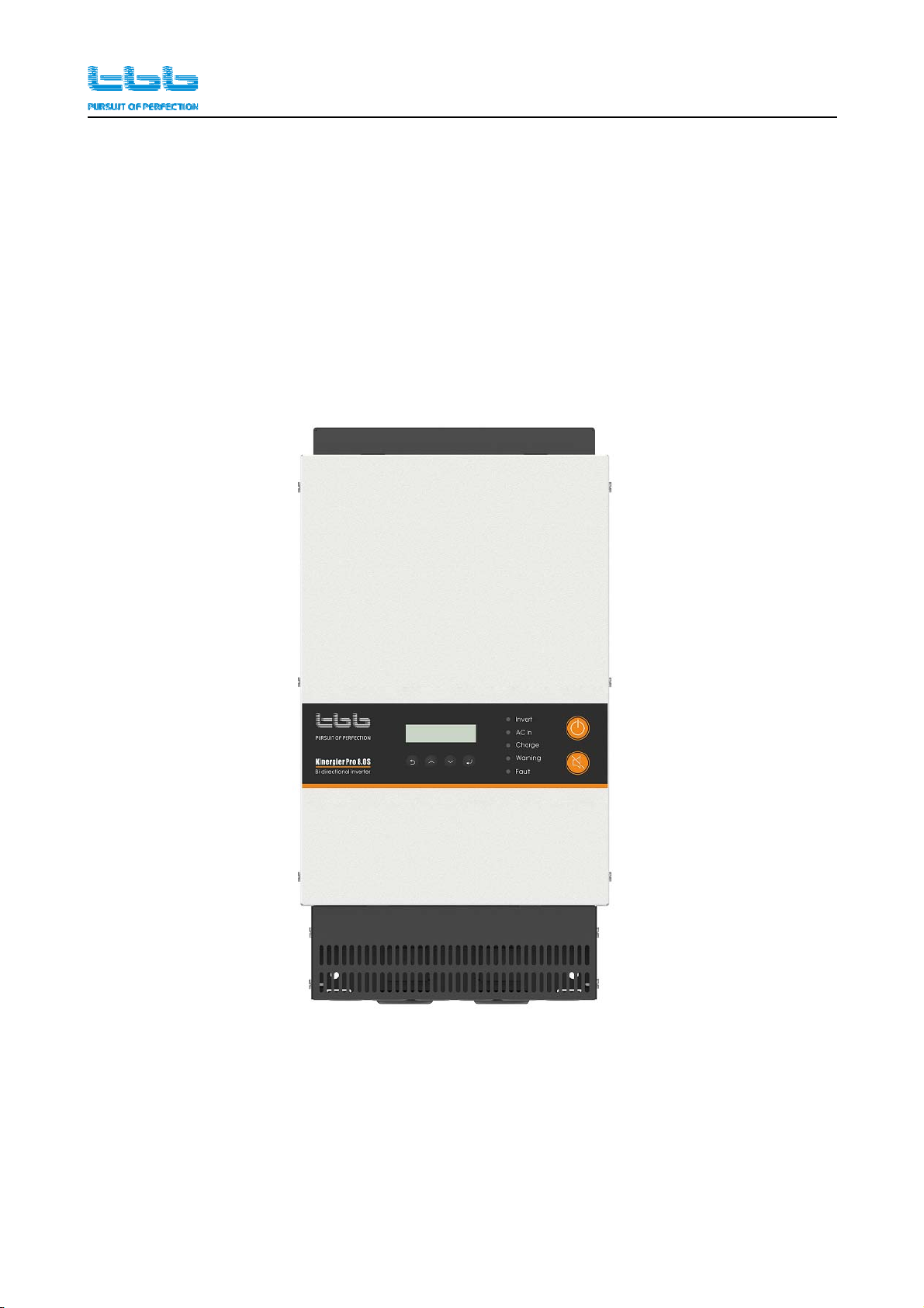
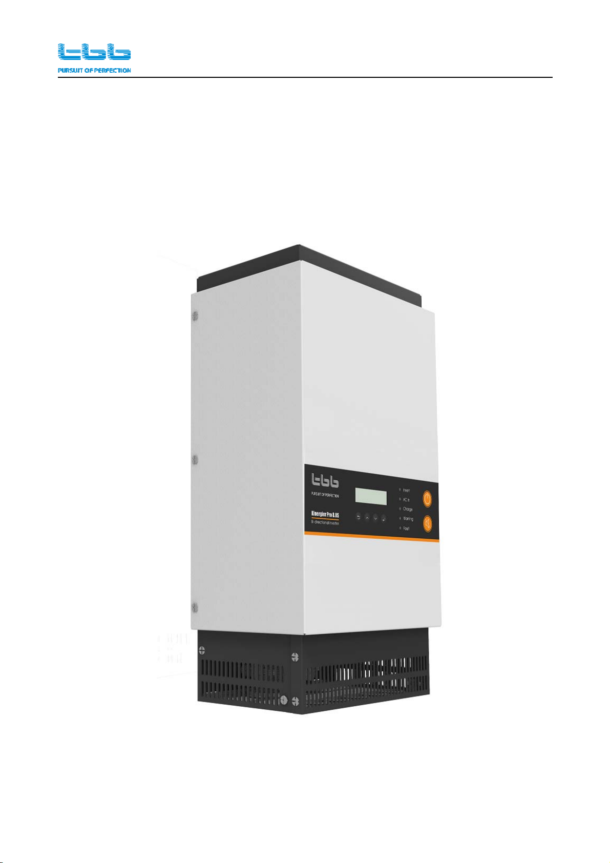
3.1.1
3.1.1 Kinergier
Kinergier pro
pro bi-directional
bi-directional inverter
inverter
1) CK 4.0S/6.0S/8.0S

Kinergier pro bi-directional inverter User Manual
TBB Power Co., Ltd 9
3.2
3.2 Product
Product size
size
3.2.1
3.2.1 Kinergier
Kinergier pro
pro bi-directional
bi-directional inverter
inverter
1)CK 4.0S/6.0S/8.0S
Kinergier pro bi-directional inverter User Manual
TBB Power Co., Ltd 10
4.
4. Pre-installation
Pre-installation Configuration
Configuration
4.1
4.1 Unpacking
Unpacking and
and inspection
inspection
4.1.1
4.1.1 Inspection
Inspection of
of appearance
appearance
Please confirm whether the equipment is damaged during transportation and whether the
accessories are complete after unpacking.
4.1.2
4.1.2 Packing
Packing list
list
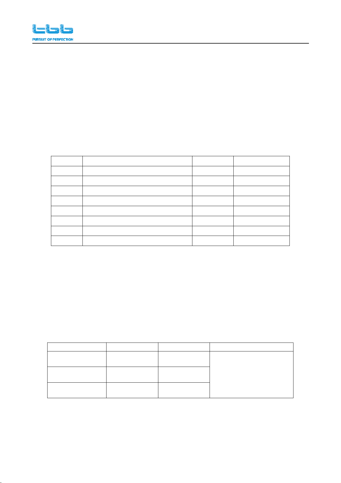
No. Category Quantity Remark
1. Bi-directional inverter 1
2. BTS - battery temperature sensor 1
3. Wall mount 1
4. Expansion screw 4
5. Hex Screw,M6*40mm 4
6. User
,
manual 1
7. 8P8C communication cable, 2m 1
8. 4P4C communication cable, 2m 1
The equipment should be transported to the installation site and then the outer packaging
should be removed. Check the various equipments and materials are correct according to the
packing list in this manual, and properly keep all kinds of spare parts and accessories for later
installation and upgrade equipment or maintenance.
4.2
4.2 Wiring
Wiring recommendation
recommendation
Please find the following minimum wire size. In case of DC cable longer than 1m, please
increase the cross section of cable to reduce the loss.
System capacity AC wiring PE wiring DC wiring
CK 4.0S 4mm²~10mm² 4mm²~10mm² 35mm²~90mm²
φ8aperturecopper
terminal
Length<2m
CK 6.0S 6mm²~10mm² 6mm²~10mm²
CK 8.0S 8mm²~10mm² 8mm²~10mm²
Kinergier pro bi-directional inverter User Manual
TBB Power Co., Ltd 11
4.3
4.3 Tools
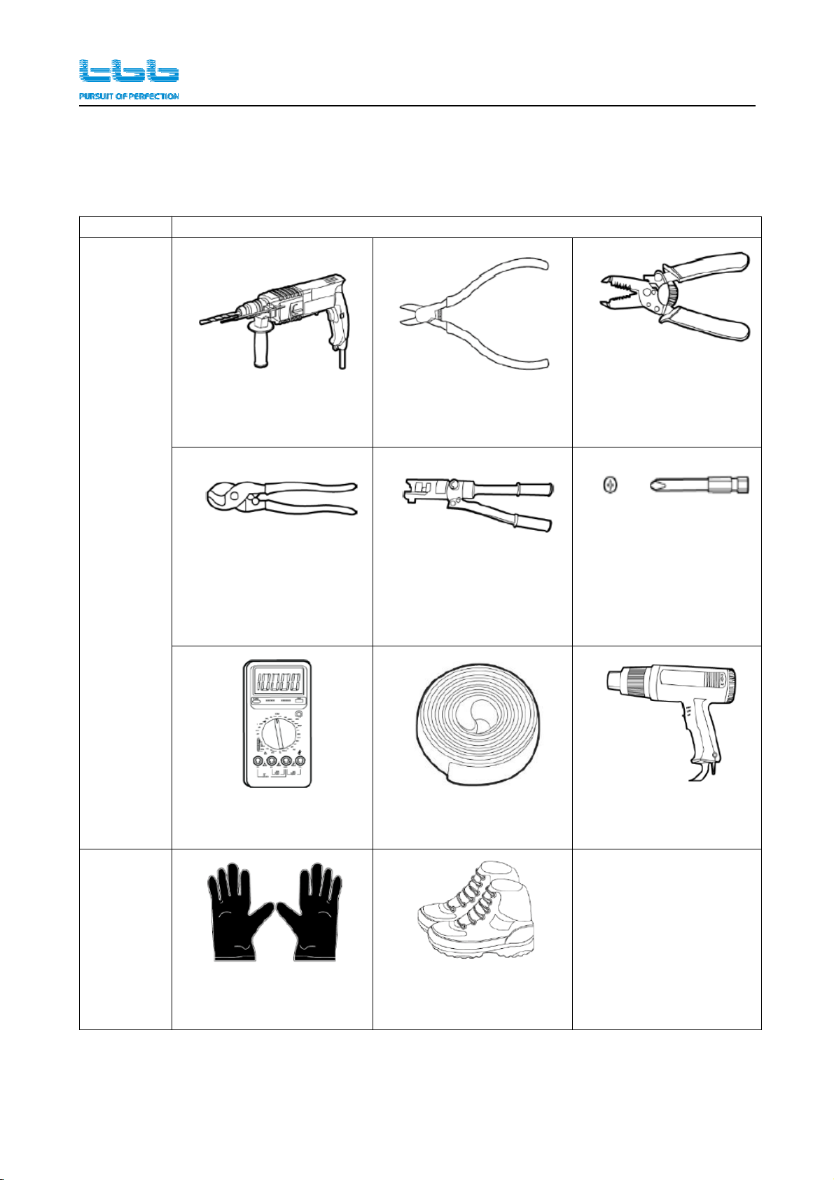
Please prepare tools and instruments following the Tab in advance.
Classify Tools and instruments
Installing
Percussion drill (φ8mm) Diagonal pliers Wire stripper
Wire cutters
(25mm²~35mm²)
Hydraulic pliers
(25mm²~35mm²)
Cross screwdrivers
(M4、M6)
Universal meter(600V)Heat-shrinkable tubing Heat gun
Personal
safety
equipment
Protective gloves Protective shoes
Kinergier pro bi-directional inverter User Manual
TBB Power Co., Ltd 12
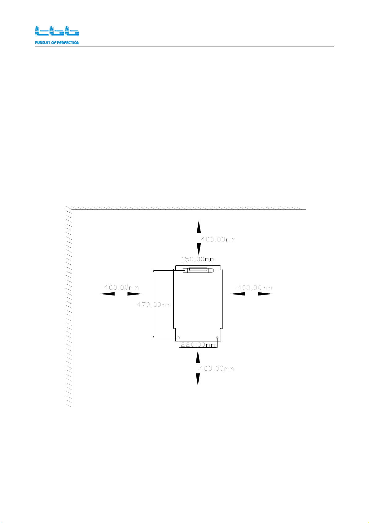
4.4
4.4 Location
Location
Keep away from fire, avoid direct sunlight and rain; do not store flammable,
explosive or corrosive gases or liquids in the working environment. Don't install in
a working environment with metal conductive dust.
Please install the equipment in a location of dry, clean, cool with good ventilation.
Operating temperature: -20~60℃
Storage temperature: -40~70℃
Cooling: Force fan
Relative humidity in operation: 95% without condensation.
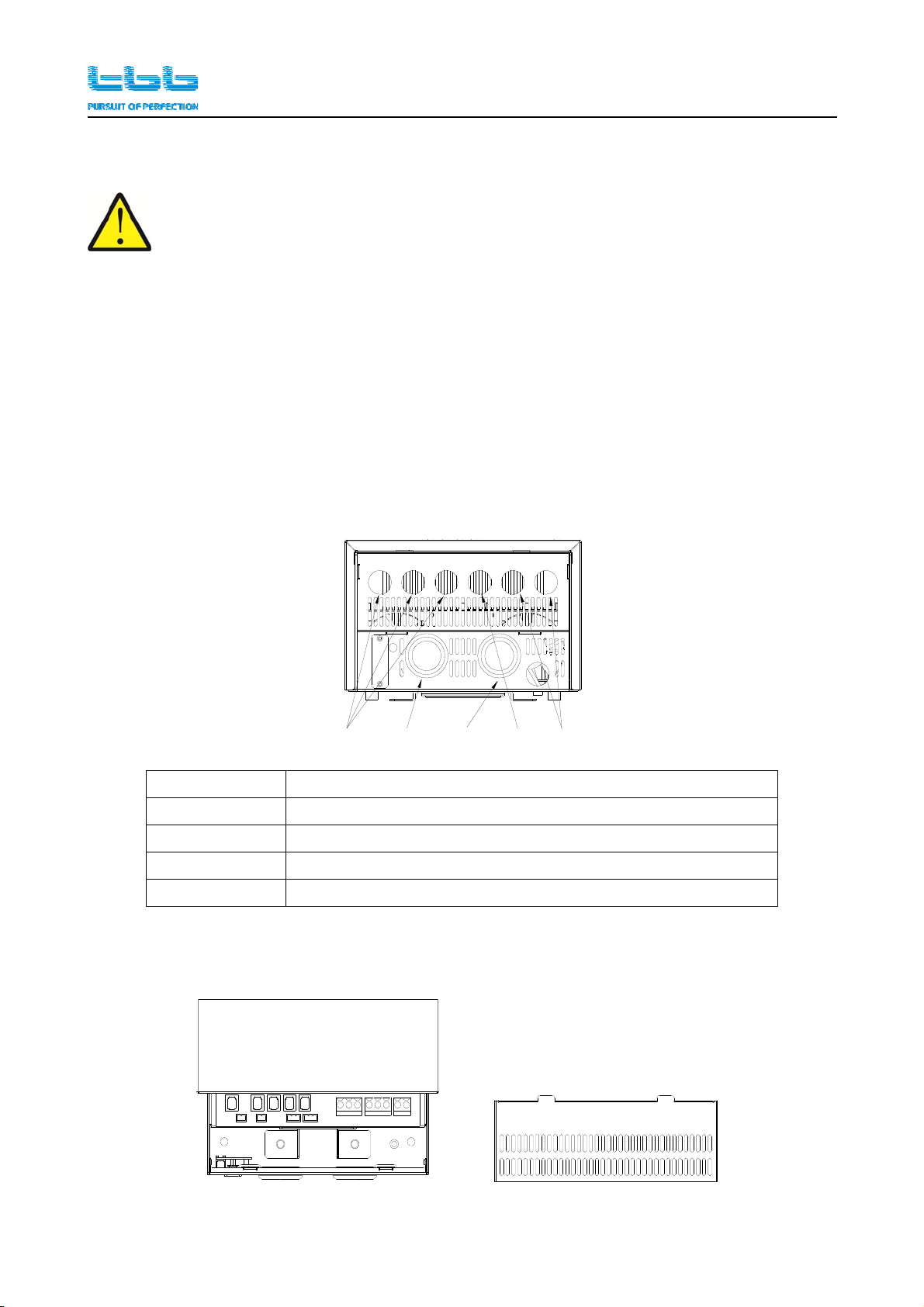
4.5
4.5 Installation
Installation interface
interface
Front panel
A B CDE
A Communication cable, dry contact cable threading hole
B Battery negative cable threading hole
C Battery positive cable threading hole
D AC input cable threading hole
E AC output cable threading hole
Remove the top panel

Kinergier pro bi-directional inverter User Manual
TBB Power Co., Ltd 13
5.
5. Installation
Installation And
And Connection
Connection
5.1
5.1 General
General advice
advice
Ensure that the Kinergier pro bi-directional inverter has the correct DC voltage with the
existing battery system.
Install Kinergier pro bi-directional inverter as close to the batteries as possible reducing the
voltage drop on cable for the better performance of the equipment.
We recommend connecting a DC fuse corresponding to the conductor between battery and
Kinergier pro bi-directional inverter, which will offer protection to the battery cable. Please
refer to following chart of our recommendations.
Type 48Vdc
CK 4.0S 125A/80V
CK 6.0S 200A/80V
CK 8.0S 250A/80V
On the AC output side, we recommend connecting the output from Kinergier pro
bi-directional inverter to a suitable Residual Current Circuit Breaker and Circuit Breaker.
Please make sure Kinergier pro bi-directional inverter is turned off before
connection. Otherwise, high voltage could be present.
Fo
r
the use
r
o
p
eration safet
y,
cut off the
p
ower before installation.
Kinergier pro bi-directional inverter User Manual
TBB Power Co., Ltd 14
5.2
5.2 Fix
Fix the
the bi-directional
bi-directional inverter
inverter
Basically, Kinergier pro bi-directional inverter could be installed either vertically on wall or
horizontally on floor.
Take the case of installing on the wall as an example, please choose a flat surface to fix the unit
securely.
Step1:Punch the wall according to the mounting hole cardboard.
step2:Fix the mount to the wall with 2*M6 screws.
step3:Snap the bottom hook into the wall mount.
step4:Fix the bottom plate to the wall with 2*M6 screws.
Step 1
This manual suits for next models
3
Table of contents
Other TBB Inverter manuals


