Siel SOLEIL DSPX TLH 1500 User manual
IV408E
Rev.
0
1
Installation manual
Dateof issue
: 20
21
-
03
-
1
0
Pag.
1
di
26
Inverter for photovoltaic applications
INSTALLATION MANUAL
SOLEIL DSPX TLH 15
EEP FOR FUTURE REFERENCE
for the entire life of the appliance

IV408E
Rev.
0
1
Installation manual
Dateof issue
: 20
21
-
03
-
1
0
Pag.
2
di
26
INDICE
1
AIM OF THE DOCUMENT .................................................................................................................................... 3
1.1
O
VERVIEW
............................................................................................................................................................ 3
1.2
G
RAPHIC SYMBOLS USED
.......................................................................................................................................... 3
2
POSITIONING...................................................................................................................................................... 5
3
POWER CONNECTIONS AND AUXILIARIES .......................................................................................................... 6
3.1
M
ECHANICAL LAYOUT
............................................................................................................................................. 6
3.2
C
ABLE QUANTITY AND SECTION
................................................................................................................................. 9
3.3
G
ROUND CONDUCTOR
S
IZING
................................................................................................................................. 10
3.4
M
AXIMUM TORQUE TIGHTENING CABLES
.................................................................................................................. 11
3.5
FAN
CHARACTERISTIC
........................................................................................................................................... 11
4
INSTALLATION .................................................................................................................................................. 12
4.1
V
ISUAL INSPECTION
.............................................................................................................................................. 12
4.2
U
NPAC ING
........................................................................................................................................................ 12
4.3
S
AFETY CONSIDERATIONS
....................................................................................................................................... 14
4.4
E
NVIRONMENTAL CONSIDERATIONS
......................................................................................................................... 15
4.4.1
Load-bearing capacity of the floor .............................................................................................................. 15
4.4.2
Temperature and humidity ......................................................................................................................... 15
4.5
I
NSTALLATION
L
OCATION OF INVERTERS
.................................................................................................................... 15
4.6
I
NSTALLATION
L
OCATION OF OUTDOOR INVERTERS
...................................................................................................... 16
4.7
POSITIONING
AND
VENTILATION .................................................................................................................... 16
4.8
E
LECTRICAL CONSIDERATIONS
................................................................................................................................. 17
4.9
M
EDIUM TO
L
OW VOLTAGE TRANSFORMER FOR CONNECTION TO
MV
GRID
:
CRITERIA OF CHOICE
. ....................................... 17
4.10
P
REVENTIVE
M
AINTENANCE
................................................................................................................................... 17
5
BASIC INSTALLATION HINTS ............................................................................................................................. 18
5.1
P
OSITIONING OF THE INVERTERS AND VENTILATION
..................................................................................................... 18
6
SYNCHRONIZATION CABLE AND CAN-BUS (MULTI-INVERTER SYSTEMS) .......................................................... 19
7
CONNECTION OF THE EPO CIRCUIT (EMERGENCY POWER OFF) ........................................................................ 21
7.1
C
ONNECTION OF THE MODULES
’
TEMPERATURE SENSOR
.............................................................................................. 21
8
SERIAL COMMUNICATION CONNECTIONS ........................................................................................................ 22
8.1
T
YPE OF CABLES TO BE USED
................................................................................................................................... 22
8.2
M
ONITORING SYSTEM AND
P
OWER
P
LANT
C
ONTROLLER
(PPC)
RS485
M
ODBUS COMMUNICATION
................................... 22
8.3
C
ONNECTION OF THE
M
ODBUS SERIAL PORT SHIELD
.................................................................................................... 22
8.4
C
ONNECTION OF THE
SAC
BUS
SERIAL SHIELD
........................................................................................................... 22
8.5
R
ULES FOR THE LAYING OF
RS485
SERIAL CABLES
....................................................................................................... 22
9
USER SETTINGS ................................................................................................................................................. 25
9.1
C
ONNECTING AN INPUT POLE TO THE PHOTOVOLTAIC FIELD EARTH
................................................................................. 25
9.2
C
ONTROL FEATURES
–
N
ETWOR SERVICES
................................................................................................................ 26
IV408E
Rev.
0
1
Installation manual
Dateof issue
: 20
21
-
03
-
1
0
Pag.
3
di
26
1AIM OF THE DOCUMENT
1.1 Overview
This document constitutes a rapid guide for the installation of the product in the operating room and
provides summary and schematic instructions for the positioning and network connection of the product
and signal connections.
In no way can this document be considered a substitute for the IV346
Instruction Manual to which reference is made particularly for the
recommendations contained in it on the issue of safety regarding the handling
and electrical connection of the equipment.
The failure to follow the recommendations contained in the IV346 Instruction
Manual may have serious consequences, such as the destruction of the
apparatus, injury to persons and death due to electrocution.
The information and technical features contained in this manual refer to the
date of the drafting of the document. SIEL SPA reserves the right to modify
such technical features at any moment and without warning.
1.2 Graphic symbols used
The following symbols are used in this manual to warn and inform users of particular situations of special
importance. The symbols used and their meanings are explained below.
Simbolo
Descrizione
INFORMATION
Supplementary description to be taken into due consideration.
Used for important notes and/or recommendations
CAUTION
Danger (situation which may cause severe injuries to persons and/or damage to
equipment)
ELECTRICAL DANGER
Serious risk of electrocution.
These warnings signal compulsory behaviour.
UNPACKING INSTRUCTIONS
Describe how to unpack equipment.
IV408E
Rev.
0
1
Installation manual
Dateof issue
: 20
21
-
03
-
1
0
Pag.
4
di
26
INSTALLATION INSTRUCTIONS
Describe the inverter installation process step by step.
MANDATORY INSTRUCTIONS
Read and understand the instruction manual before working on the inverter.
DISPOSAL
Contains information useful for disposal of the equipment.
THE WARNING TRIANGLES INDICATE INSTRUCTIONS REGARDING SAFETY FOR
STAFF. FOLLOW THEM CAREFULLY TO AVOID DAMAGES TO PERSONS OR OBJECTS.

IV408E
Rev.
0
1
Installation manual
Dateof issue
: 20
21
-
03
-
1
0
Pag.
5
di
26
2POSITIONING
In the installation of the Soleil product, it is recommended that the distance
between the inverter and any walls or other objects be respected, as shown in
the following diagrams.
SOLEIL DSPX xxxx TLH 15
3
cm
1
cm
1
cm

IV408E
Rev.
0
1
Installation manual
Dateof issue
: 20
21
-
03
-
1
0
Pag.
6
di
26
3POWER CONNECTIONS AND AUXILIARIES
3.1 Mechanical layout
The following figures illustrate the power terminals of the DC (input) and AC (output) sections.
Frontal view of the inverter:
Internal view of the inverter:
Display Touch-screen User
interface
Air-intake grid for power
modules
Air-intake grid for magnetic
cores
Power core ‘B’
Power core ‘A’
Input DC Switch
Fuses and SPD
Output AC Circuit
Breaker
IV408E
Rev.
0
1
Installation manual
Dateof issue
: 20
21
-
03
-
1
0
Pag.
7
di
26
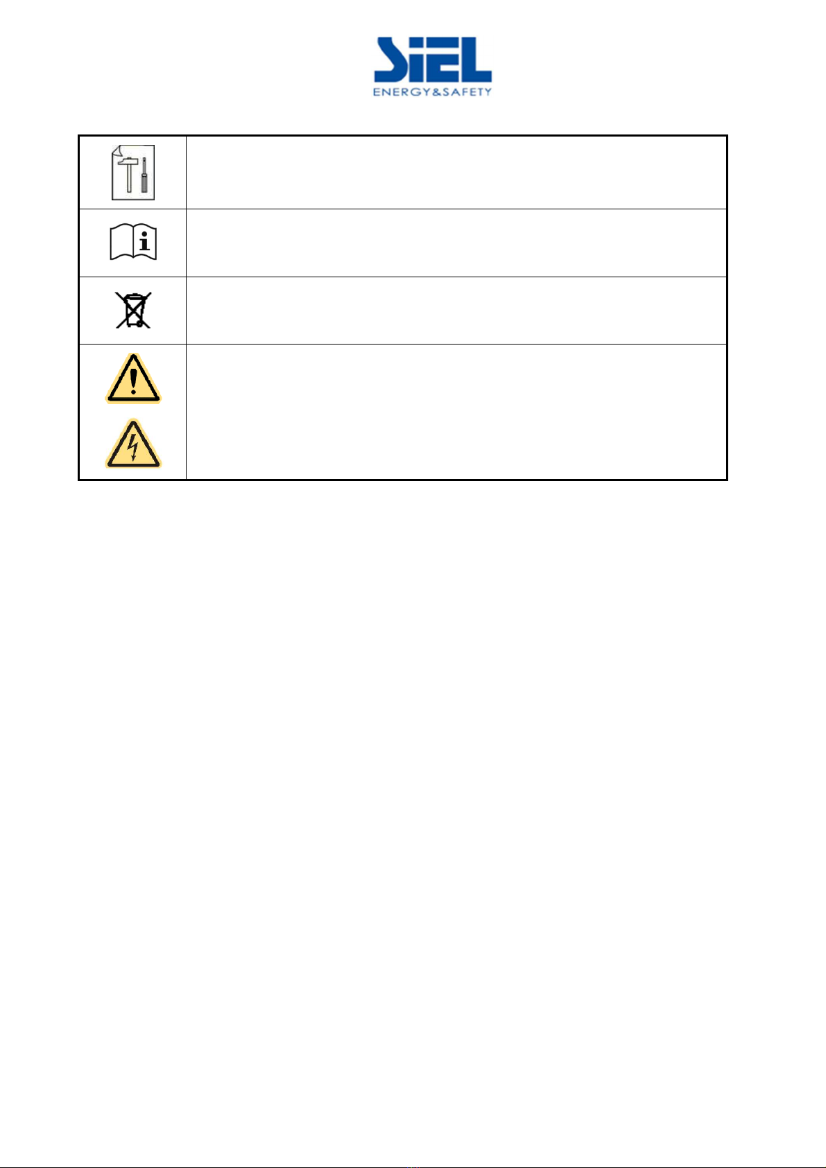
DC Terminal side:
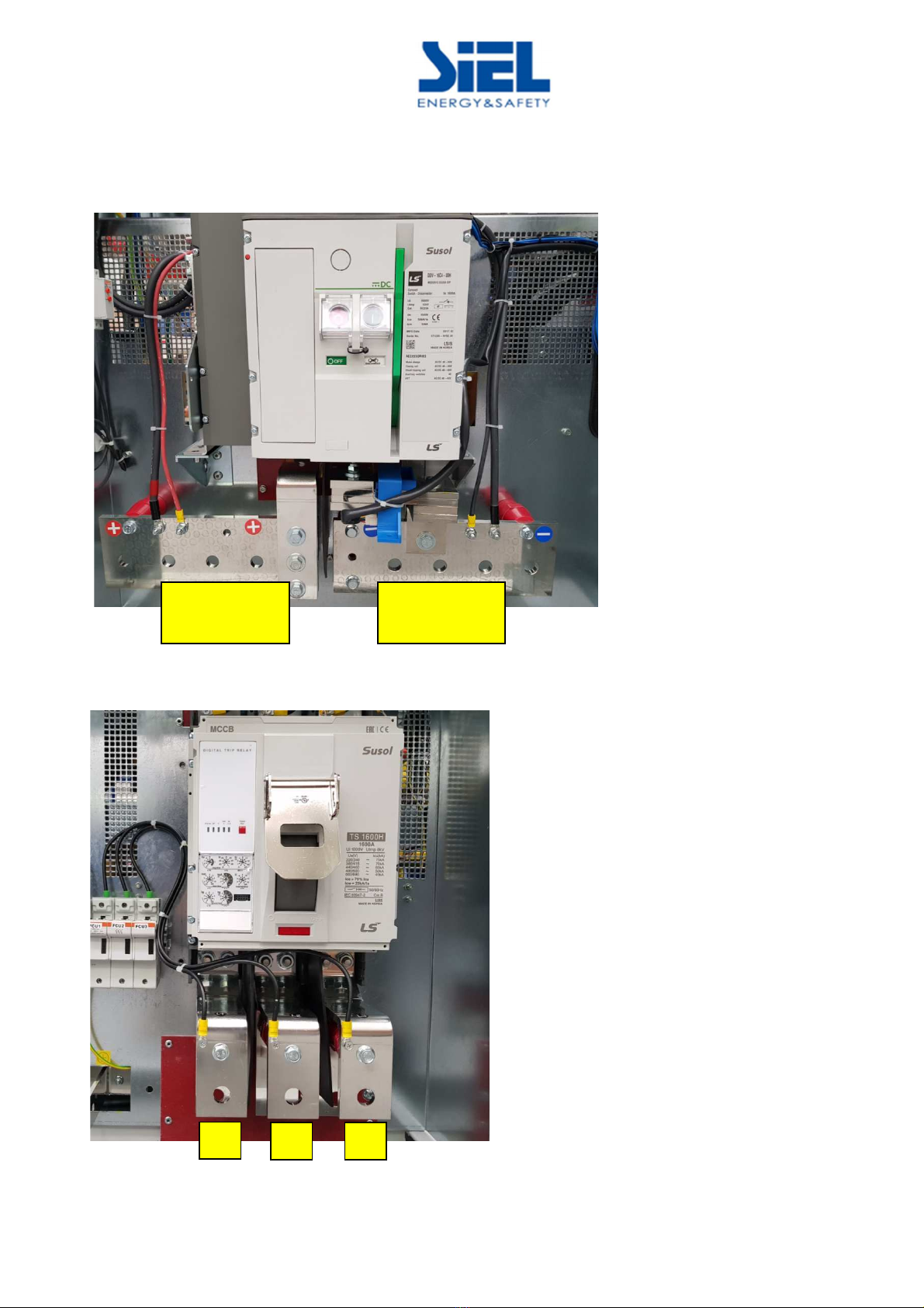
AC terminal side:
Positive pole
(+)
Negative pole
(-)
L1
L2
L3

IV408E
Rev.
0
1
Installation manual
Dateof issue
: 20
21
-
03
-
1
0
Pag.
8
di
26
Connecting AC side cables are dimensioned taking into account the electrical parameters of the circuit
breakers, summarised in the following table:
Current(A)
-
Curve
Magnetic curve
Breaking capacity [kA]
1600A
10 In (Programmab
le
)
50kA
The characteristics (curve type, magnetic current) of the switch on the
electrical board connected to the inverter must be compatible with the
characteristics of the machine switch.
IV408E
Rev.
0
1
Installation manual
Dateof issue
: 20
21
-
03
-
1
0
Pag.
9
di
26
3.2 Cable quantity and section
The following tables indicate the maximum quantity and the maximum section of copper-made cables
that can be connected to the DC input and the AC output.
Inverter soleil DSPX xxxx TLH 15
Inverter 55 665 7 8 75 11 M 133 M 1415M 15 M
AC Cables ( cables number x section in mmq )
Suggerito 2 x 400 2 x 400 2 x 400 2 x 400 4 x 400 4 x 400 4 x 400 4 x 400
DC Cables (cables number x section in mmq)
Suggerito 2 x 400 2 x 400 2 x 400 2 x 400 4 x 400 4 x 400 4 x 400 4 x 400
Ground Conductor (PE) (cables number x section in mmq)
Suggerito 1 x 240
(Nota 1)
1 x 240
(Nota 1)
1 x 240
(Nota 1)
1 x 240
(Nota 1)
1 x 300
(Nota 1)
1 x 400
(Nota 1)
1 x 400
(Nota 1)
1 x 400
(Nota 1)
Note 1: Refer to the table for the sizing of the earth wires for the calculation of the total cable section
The type of cable and its cross section to be used must be determined at the design stage by the designer
or installer
IV408E
Rev.
0
1
Installation manual
Dateof issue
: 20
21
-
03
-
1
0
Pag.
10
di
26
3.3 Ground conductor Sizing
The size of the ground conductor must be made according to the following table, extracted from the
product Safety standard CEI EN 62109-1.
The cross section of the phase conductors
connected to the inverter, ‘S’
mm²
Relevant minimum cross section of the
protective conductor to the ground, Sp
S ≤ 16
16 < S ≤ 35
35 < S
S
16
S/2
NOTE: The values shown in the previous table are valid only if the protective earthing conductor is made of the same
material used for the phase conductors AC. If not, the cross section of the protective conductor to ground must be
determined in order to get the same conductance value equivalent.
IV408E
Rev.
0
1
Installation manual
Dateof issue
: 20
21
-
03
-
1
0
Pag.
11
di
26
3.4 Maximum torque tightening cables
Coppia massima di serraggio
Ingresso DC
Uscita AC
Cavo di Terra
30 N m
3.5 FAN characteristic
The following table includes the air flow volume and the power dissipation values
.
Model
Air capacity
aria [m³/h]
Inverter
FAN
Air capacity
aria [m³/h]
Magnetics
FAN
Inverter
FAN
consumption
[W]
Magnetics
FAN
consumption
[W]
Dissipated
power
[kW]
SOLEIL DSPX 1528M TLH 1500
7000 4000 1200 420
17,5
SOLEIL DSPX 1415M TLH 1500
17,5
SOLEIL DSPX 1330M TLH 1500
16,5
SOLEIL DSPX 1100M TLH 1500
13,5

IV408E
Rev.
0
1
Installation manual
Dateof issue
: 20
21
-
03
-
1
0
Pag.
12
di
26
4INSTALLATION
4.1 Visual inspection
All inverter components (electrical and mechanical) are carefully inspected
before the unit is delivered to the customer and must be integral even after
delivery. Always visually check a UPS after delivery for any transit damage, and
immediately inform Siel SPA if such damage is evident.
4.2 Unpacking
The inverter packaging is usually consitituted by a plastic ground cloth, put on from the top part of the
equipment and lowered till the lower limit of the equipment. Above the ground cloth, a carton box is
secured with plastic strips.
In order to unpack the inverter, it firstly required to cut the plastic strips and push the carton toward the
top of the unit, until the equipment is totally out of the box. Once this operation is done, it is possible to get
the inverter out of its plastic ground cloth.
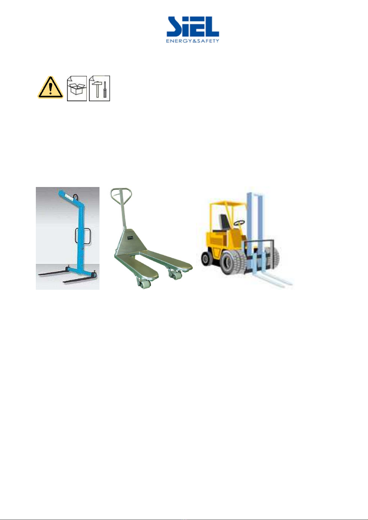
Removal from the pallet: please use a forklift (with proper capacity for weight). Please refer to chapter
(TECHNICAL INFORMATION) of this manual to retrieve the weight information.
Forks of the forklift have to be inserted either from the front or from the rear of the cabinet (never from
the lateral side of it).
Due to the eight of the equipment, it is strongly recommended the use of all the safety tools as
prescribed by the safety regulation in force in any specific country here the equipment is installed.
IV408E
Rev.
0
1
Installation manual
Dateof issue
: 20
21
-
03
-
1
0
Pag.
13
di
26
The drive comes with plinths which close the base of the equipment.
When the apparatus comes from the factory skirtings are not mounted
so that it can be lifted from the bottom with a forklift.
Please do not tilt or lay down the inverter on either lateral side.
Following tools can be used for tran sport:
- Crane Forks
- Forklift
- Transpallets
Please use only tools designed to stand the weight of the inverter to be lifted.
In case of a pre-installed inverter removal, please remove the grid at the bottom of the equipment.
For weights and dimensions refer to the chapter "T CHNICAL INFORMATION" section of the instruction
manual.
Due to the order of magnitude of the weights, it is strongly recommended to use all the safety devices
required by current safety-related standards for movement and placement.

IV408E
Rev.
0
1
Installation manual
Dateof issue
: 20
21
-
03
-
1
0
Pag.
14
di
26
4.3 Safety considerations
Accidents can be prevented by simply following a few precautions:
•Walls, ceilings, floors and any other item placed next to the converter
should not be made of inflammable materials.
•The floor on which the inverter is installed should always be kept clean to
prevent metal particles or scraps of iron or metal from being sucked inside
the unit and causing short circuits.
•A dry powder fire extinguished should be positioned at the installation
site.
•For units of 100kW or higher, an automatic fire-fighting system should be
installed (as explained in the section “choice of installation site”).
•Access to the inverter installation site should only be given to service staff
and maintenance personnel; inward opening doors (with handles) to the
room where the inverted is sited and to the inverter itself) should be kept
closed at all times (limited access area).
•All service and electrical maintenance personnel must be trained and able
to perform both ordinary and emergency procedures. New personnel
must be given suitable training before being allowed to work on inverters.

IV408E
Rev.
0
1
Installation manual
Dateof issue
: 20
21
-
03
-
1
0
Pag.
15
di
26
4.4 Environmental considerations
The environmental factors that need to be taken into account are detailed in
the paragraphs that follow.
4.4.1 Load-bearing capacity of the floor
The weight of the inverter (specified in the Technical specifications in the instruction
manual) is taken by a small floor area. Therefore, it is important to make sure that the
area selected for installation can bear the weight of the appliance.
If the UPS is installed on a raised floor, it is important to use a base with pedestals (this
base can be provided by Siel SPA upon request).
All cables should be routed from below the floor.
4.4.2 Temperature and humidity
The premises where the inverter is to be installed must be able to disperse the
w that the device gives off during operation to keep the temperature
between -5°C and 45°C; with a humidity percentage between 0 and 95% as
shown on the technical specifications table.
The type and the implementation of any air distribution line must be checked
and approved by Siel SPA. The manufacturer is not in any way liable for
inverter malfunctions due to the failure to observe the rules of Installation,
particularly the permitted temperature and humidity requirements. It is
recommended therefore to adopt design features (for example air-
conditioning, heating or dehumidification of the premises), suitable to
guarantee the maintenance of the permitted temperature and humidity
conditions.
4.5 Installation Location of inverters
The inverter must be installed on a stable, level surface that is longer and wider than
the base of the appliance.
The inverter is not designed to be installed in areas where it could be exposed to
impacts or vibration: being transported by road, rail, sling, air or ship or by similar
equipment (e.g. cranes, moving parts of the appliance etc.).
IV408E
Rev.
0
1
Installation manual
Dateof issue
: 20
21
-
03
-
1
0
Pag.
16
di
26
The room intended for installation of the inverter must be a access-restricted only, such
as containers, electrical substations or suitable technical rooms suited to accommodate
electrical power, where no risk of items falling from above is present. The requirement
of security to prevent falling objects from that area is IP3X.
For indoor-type inverters, the installation site must be kept clean and dry at all
times so as to prevent foreign material or liquids from entering the
equipment.
1 m clearance, at least, must be kept in front of the inverter to allow all
routine and maintenance operations to be carried out.
The top of the equipment should be positioned at least 1m from the ceiling in order to
ensure good ventilation.
As these appliances can reach significant power levels, the site where an
inverter is positioned should be fitted with an automatic smoke detector that
has a remote alarm system that stops the unit and cuts off the power supply.
The detector should also be able to set off a fire-fighting system suitable for
an electrical device.
4.6 Installation Location of outdoor inverters
The inverter must be installed on concrete reinforced basement, such to stand the
weight of the inverter. The basement has to be prepared with cable conduits and
fixation holes before the installation. The inverter has to be secured to the basement
through dedicated screws inserted into the fixation holes.
The inverter is not designed to be installed in areas where it could be exposed to
impacts or vibration.
4.7 POSITIONING AND VENTILATION
Although “SOLEIL DSPX” series inverters are highly efficient, be aware that during
normal operation a certain amount of heat is generated. If this heat is not properly
dissipated, it can lead to an increase in temperature in the room where the inverter is
located and so the inverter itself can start to overheat.

IV408E
Rev.
0
1
Installation manual
Dateof issue
: 20
21
-
03
-
1
0
Pag.
17
di
26
4.8 Electrical considerations
Please refer to document IT0068 “Guidelines for the creation of photovoltaic plants” for the design
recommendations for the creation of LV and MV plants based on SOLEIL DSPX inverters.
4.9 Medium to Low voltage transformer for connection to MV grid:
criteria of choice.
The choice of MV/LV transformer for connection to MV grid, has to be done paying attention to the hints
provided by document IT0124 ‘Technical Properties MV trafo for oleil TL D PX 1000&1500Vdc’.
4.1 Preventive Maintenance
To ensure the functionality of the inverter over time, it is necessary to carry out some checks periodically:
-Check status connections (any oxidation) - Annual
-Check tightening of power connections - Annual
-Check tightening signal connections (terminals) - Annual
-Check correct operation of the cooling fans – Every 6 months
-Check integrity of fuses – Every 6 months
The equipment must also internally and externally cleaned-up, at least every six months.
It is strongly recommended to replace capacitors AC side and DC before the end of life expectancy (10
years). This activity, due to its complexity, requires being done by qualified personnel.
Replacement of fans is better done at intervals of five years, to prevent their failure or performance de-
rating due to the aging of its components (rotor, winding, bearings, etc.)
All the above operations and access to the internal components have to be carried out by trained
technicians.
During operation the inverter must be switched off and secured, opening the switches / disconnectors
side AC and DC side,
Particularly, for access to the upper compartment and the rear part of the unit:
1- disconnect the DC input
2- disconnect the AC output
3- if the fans are po ered by an external source, please make sure that the external s itch for
selecting the source of the aux circuits, is open.
To access the lower compartment, where the connection terminals and bars are located, in addition to
the steps described above, it is necessary to disconnect the incoming DC source from the photovoltaic
field and open the AC switch downstream the inverter.
Before accessing any part of the inverter, make sure that the capacitors are completely discharged and
that the fans are not operating.

IV408E
Rev.
0
1
Installation manual
Dateof issue
: 20
21
-
03
-
1
0
Pag.
18
di
26
5BASIC INSTALLATION HINTS
This Chapter contains a brief summary of the criteria for a correct installation of a multi-inverter system, in
order to get it into operation in the quickest and most reliable way.
5.1 Positioning of the inverters and ventilation
The positioning of the inverter has to take into account the type of installation:
Dedicated concrete-made technical room : the inverter can be positioned either on a floating floor
or on a concrete soil (in this case, power cables have to be routed to the inverter’s power
connection through underground dedicated conduits). In both cases, a dedicated mounting kit
provided by SIEL has to be used to secure the inverter to the hosting surface.
Containerized Metal Conversion Unit: the best practice to position the inverter, is placing it on a
metal frame of crossbeams, covering the perimeter of the inverter itself.
A dedicated mounting kit provided by SIEL has to be used to secure the inverter to the metal frame.
Regardless of the type of installation, the inverter has to lie on a horizontal surface, able to carry at least
1000kg/m^2.
If the system is a multi-inverter system, all the inverters have to be placed one beside the other, all front-
sided, as per following figure (example: DSPX TLH 5660M TLH 1500):
Fresh air intake is from the front , hot air exhaust from
the rear of the unit.Proper clearance (1m from the front,
1m from the rear side) must be left respect to walls and
possible obstacles, in order to ensure proper ventilation
to the inverter.
Following table shows the required minimum air flow:
Model
Air flow (m^3/h)
550, 665, 708
, 750
5500
1100M, 1330M, 1415M
, 1500M
11000
2200M, 2660M, 2830M
, 3000M
22000
3300M, 4000M, 4245M
, 4500M
33000
4400M, 5330
M
, 5660
M
, 6000M
44000

IV408E
Rev.
0
1
Installation manual
Dateof issue
: 20
21
-
03
-
1
0
Pag.
19
di
26
6SYNCHRONIZATION CABLE AND CAN-BUS (MULTI-INVERTER
SYSTEMS)
In multi-inverter models (2200M, 2660M, 2830M, 3000M, 3300M, 4000M, 4245M, 4500M, 4400M, 5330M,
5660M, 6000M), every inverter is connected in a daisy-chain fashion with the next one and the previous
one (except the Master and the last inverter of the system) as far as:
•Synchronization channel: the synchronized firing commands are received by one unit on the
‘Interface Board’ and retransmitted forward, by using a twisted multi-conductor, shielded cable ,
terminated with a multi-pole DIN connector (link ‘Sync_in’ & ‘Sync_out’ in the figure below).
• CAN-bus channel: the CAN link carrying the status information of every unit, is received by one
unit on the ‘DSP control board’ and retransmitted forward, by using a twisted multi-conductor
shielded cable for high frequency, terminated with a CAT5 – RJ45-like connector (‘CAN-in’ & ‘CAN-
out’ in the figure below).
As anticipated, these two communication links are functional to the Master & Slave operation of
the system.
In a multi-inverter system, the overall length of these two connection has to be kept as low as possible and,
however, less than 20m, for signal integrity and timing constraints.
This is the main reason why, as recommended in previous paragraph, it is essential to keep the inverters
aligned to each other on the front side.
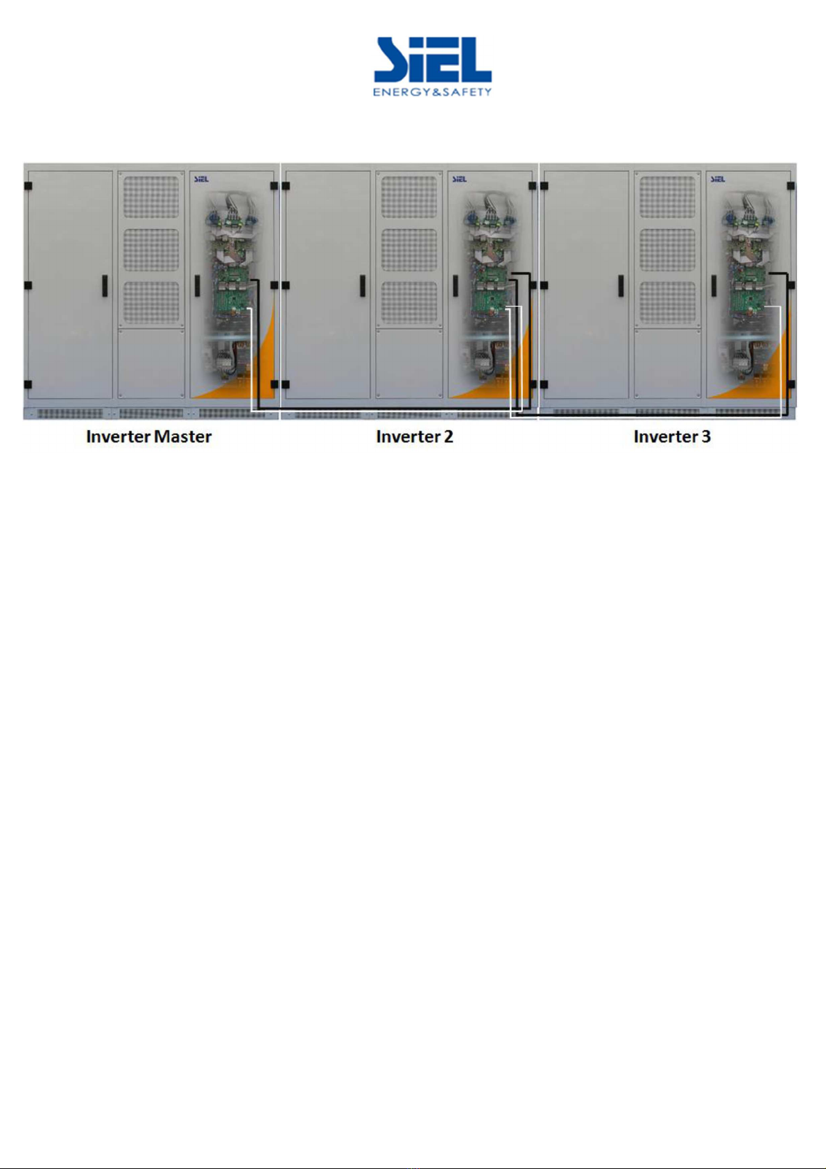
Next figure shows the path of both ‘Sync’ and ‘CAN’ connections among units:
IV408E
Rev.
0
1
Installation manual
Dateof issue
: 20
21
-
03
-
1
0
Pag.
20
di
26
SINCHRONIZATION AND CAN BUS CONNECTION EXAMPLE (DSPX 4 M TLH 15 )
•Synchronization connections: black lines
•CAN bus connections: white lines
This manual suits for next models
4
Table of contents
Other Siel Inverter manuals


Popular Inverter manuals by other brands


SolarEdge
SolarEdge StorEdge SE5000H-O4 quick guide

Patron
Patron GI-3500P user manual

True blue power
True blue power TI1200 Installation manual and operating instructions

Northern Lights
Northern Lights Lugger P984 Operator's manual

Atlas Copco
Atlas Copco QAX 12 Dd S2 APP instruction manual

Go Power
Go Power SOLAR EXTREME user manual