Siemens-Allis LA3000A User manual

r
SIEMENS-ALLIS
----
-
~~-~
INSTRUCTIONS
TYPES
LA3000A
&
LA4000A
(UNFUSED)
AIR
CIRCUIT
BREAKERS'
WITH
MANUAL
OR ELECTRICAL
OPERATORS
..
-18X5689
MAY,
1977
(
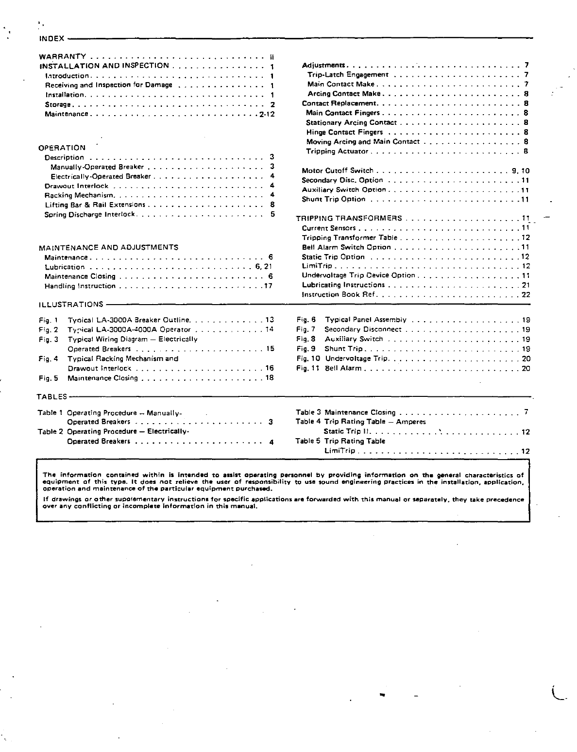
INDEX-----------------------------------------------------------------------------------
WARRANTY
.•......
"
....
INSTALLATION
AND
INSPECTION
1.1.roduction
....•..........
Receiving
and
Inspection
for
Damage
Installation
..
Storage
....
Maintenance.
OPERATION
Description
.•
_
........
.
Manually-Operated
Breaker
..
Electrically·Operated
Breaker.
Drawout
Interlock
Racking
Mechanism
...
Lifting Bar & Rail
Extensions.
Spring
Discharge
Interlock
...
MAINTENANCE
AND
ADJUSTMENTS
Maintenance
..
Lubrication
....•
Maintenance
Closing
Handling
Instruction
ii
2
.
2-12
3
3
4
4
4
8
5
. . 6
6.21
· 6
..
17
Adjustments
.......
.
Trip-Latch
Engagement
Main
Contact
Make
..
ArCing
Contact
Make.
Contact
Replacement
..
Main
Contact
Fingers
.
Stationary
Arcing
Contact
..
Hinge
Contact
Fingers
....
Moving
Arcing
and
Main
Contact
Tripping
Actuator
..
Motor
Cutoff
Switch
.
Secondary
Oisc.
OPtion
.
Auxiliary
Switch
OpTion.
Shunt
Trip
Option
....
TRIPPING
TRANSFORMERS
Current
Sensors
...
Tripping
Tran
...
former
Table.
Bell Alarm
Switch
Option
Static
Trip
OPtion
....
UmiTrip
__
Undervoltage
Trip
Oevice
Option.
Lubricating
Instructions.
Instruction
Book
Ref
..
-
.......
7
7
7
8
8
8
8
8
8
8
9.10
.11
.11
.11
·
1'.
_
.11
.12
.11
.12
·
12
.11
·
21
.22
ILLUSTRATIONS---------------------------------------------------------------------------------
Fig.
1
Fig.2
F:g.3
Tyoical
LA-30aDA
Breaker
Outline.
T,,;,ical
LA-3000A-4000A
Operator
Typical
Wiring
Diagram -
Electrically
Operated
Breakers . _
..
Fig.4
Typical
RaCking Mechanism
and
Drawout
Interlock.
Fig.5
Maintenance
Closing
·
13
14
· 15
·
16
.18
Fig.6
Fig.7
Fig.8
Fig.9
Typical
Panel
Assembly
Secondary
Disconnect
Auxiliary
Switch
.
Shunt
Trip
...
Fig.
10
Undervoltage
Trip,
Fig, 11 Bell
Alarm
...
' .
·
19
19
19
.19
.20
.20
TABLES----------------------------------------------------------------------------------------
Table
1
Operating
Procedure
-
Manually-
Table
3
Maintenance
Closing
.....
. 7
Operated
Breakers
........
. .
...........
3
Table
2
Operating
Procedure
-
Electrically·
Table
4
Trip
Rating
Table
-
Amperes
Static
Trip
11
•..••..••••
Table
5
Trip
Rating
Table
·
12
Operated
Breakers
.........
,
............
4
LimiTrip
,
.............
12
The
information
contained
within
is
intanded
to
assist
operating
personnel
by
providing
information
on
the
general
characteristics
of
equipment
of
this
type.
It
does
not
relieve
the
user
of
responsibility
to
use
sound
engineering
practices
in
the
installation,
application,
operation
and
maintenance
of
the
particular
equipment
purchased.
If
drawings
or
other
supotementary
instructions
for
specific
applications
.re
forwarded
with
this
manual
or
separately.
they
take
precedence
over
any
conflicting
or
incomplete
information
in
this
manual.
..

WARRANTY
Allis-Chalmers
"LA"
air circuit breakers are warranted to be free
of
defects
in
material and workmanship
for a period
of
one
year
from
date
of
initial operation
but
not
more
than
eighteen
months
from
date
of
shipment
by
company
_
This
warranty
is
limited to the furnishing
of
any
part
which
to
our
satisfaction has
been proven defective_Allis-Chalmers will
not
in
any case assume responsibility f
or
allied
equipment
of
any kind_(See Allis-Chalmers Warranty Form 5992.)
. . .
Typical Shipping Methods Used With
"LA"
Breakers
:
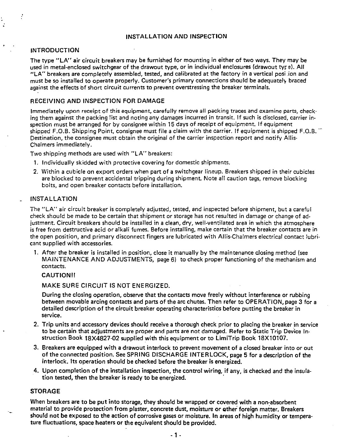
INSTALLATION AND INSPECTION
INTRODUCTION
The type
"LA"
air circuit breakers may be furnished for mounting
in
either
of
two ways. They may be
used
in
metal-enclosed switchgear
of
the
drawout type,
or
in
individual enclosures (drawout
tyre).
All
"LA"
breakers are completely assembled, tested, and calibrated
at
the
factory
in
a vertical posi :ion and
must be so installed
to
operate
properly. Customer's primary connections should be adequately braced
against
the
effects
bf
short
circuit currents
to
prevent overstressing
the
breaker terminals.
RECEIVING AND INSPECTION FOR DAMAGE
Immediately upon receipt
of
this equipment, carefully remove
all
packing traces and examine parts, check·
ing
them against
the
packing list and noting any damages incurred
in
transit. If such
is
disclosed, carrier in·
spection
must
be arranged for by consignee within 15 days
of
receipt
of
equipment.
If
equipment
shipped F.O.B. Shipping Point, consignee must file a claim with
the
carrier.
If
equipment
is
shipped F.O.B. -
Destination,
the
consignee must obtain the original of the carrier inspection report and notify Allis-
Chalmers immediately.
Two shipping methods are used with
"LA"
breakers:
1.
Individually skidded with protective covering for domestic shipments.
2.
Within a cubicle on
export
orders when part
of
a switchgear lineup. Breakers shipped
in
their cubicles
are blocked to prevent accidental tripping during shipment. Note
all
caution tags, remove blocking
bolts, and open breaker contacts before installation.
INSTALLATION
The
"LA"
air circuit breaker
is
completely adjusted, tested, and inspected before shipment,
but
a careful
check should be made
to
be certain
that
shipment or storage has
not
resulted
in
damage or change
of
ad·
justment. Circuit breakers should be installed
in
a clean, dry, well·ventilated area
in
which the atmosphere
is
free from destructive acid
or
alkali fumes. Before installing, make certain
that
the
breaker contacts are
in
the open position, and primary disconnect fingers are lubricated with Allis-Chalmers electrical contact lubri-
cant supplied with accessories.
1.
After
the
breaker
is
installed
in
position, close it manually by
the
maintenance closing method (see
MAINTENANCE AND ADJUSTMENTS, page
6)
to
check proper functioning
of
the
mechanism and
contacts.
CAUTION!!
MAKE SURE CIRCUIT
IS
NOT ENERGIZED.
During
the
closing operation, observe
that
the
contacts move freely
without
interference or rubbing
between movable arcing contacts and parts
of
the
arc chutes. Then refer
to
OPERATION, page 3 for a
detailed description
of
the
circuit breaker operating characteristics before putting
the
breaker
in
service.
2.
Trip units and accessory devices should receive a thorough check prior
to
placing the breaker
in
service
to
be certain
that
adjustments are proper and parts are
not
damaged. Refer
to
Static Trip
Dev·ice
In-
struction Book
18X4827·02
supplied with this equipment
or
to
LimiTrip Book 18X10107.
3. Breakers are equipped with a drawout interlock
to
prevent movement
of
a closed breaker into
or
out
of
the
connected position. See SPRING DISCHARGE INTERLOCK, page 5 for a description
of
the
interlock. Its
operation
should be checked before the breaker is energized.
4. Upon completion
of
the
installation inspection, the control wiring, if any,
is
checked and the insula·
tion
tested,
then
the
breaker
is
ready
to
be energized.
STORAGE
When
breakers are
to
be
put
into
storage, they should be wrapped
or
covered with a non-absorbent
material
to
provide
protection
from plaster, concrete dust, moisture
or
Qther foreign matter. Breakers
should
not
be exposed
to
the
action
of
corrosive gases
or
moisture.
In
areas
of
high humidity
or
tempera-
ture fluctuations, space heaters
or
the
equivalent should be provided.
- 1 -

MAINTENANCE
Occasional checking
and
cleaning
of
the
breaker
will
promote
long and trouble-free service. A periodic
in-
spection
and
servicing
on
an
annual basis should
be
included in
the
breaker
maintenance
routine
or
at
shorter
intervals if necessary
due
to
environmental
or
operating conditions.
If
the
circuit
breaker
is
not
operated
during
extended
periods,
the
breaker
should
not
remain
in
either
the
closed
or
open position
any
longer
than
six months. Maintenance opening and closing
operations
should be
made
to
ensure freedom
of
movement
of
all parts.
CAUTIONS TO
BE
OBSERVED IN
THE
INSTALLATION
AND
OPERATION
OF
"LA"
CIRCUIT
BREAKERS
1. Never
try
to
remove
the
breaker
from
the
compartment
or
reinsert
into
the
compartment
without
using
the
guide
rail
extensions
supplied. See page 17.
2. Read
the
Instruction
Book
before installing
or
making any changes
or
adjustments
on
the
breaker.
3.
As
the
closing springs
on
stored-energy breakers may be charged
with
the
breaker
contacts
in
either
the
open
or
closed
position.
extreme
care should be
taken
to
discharge
the
springs
before
working on
the
breaker.
4. When charging manually-operated breakers, always hold handle firmly until it
is
returned
to
the
normal
vertical position.
5. Check
current
ratings against single line diagram
to
assure
that
breakers are
properly
located
in
switch-
gear
at
installation.
6. Check
the
alignment
of
the
secondary
disconnect
fingers
to
ensure against misalignment due
to
possible
distortion
of
fingers
during
shipment
and handling.
7.
Once
the
breaker
is
energized, it should
not
be
touched,
except
for
operating, since
most
of
the
com-
ponent
parts
are also energized.
..
- 2 .
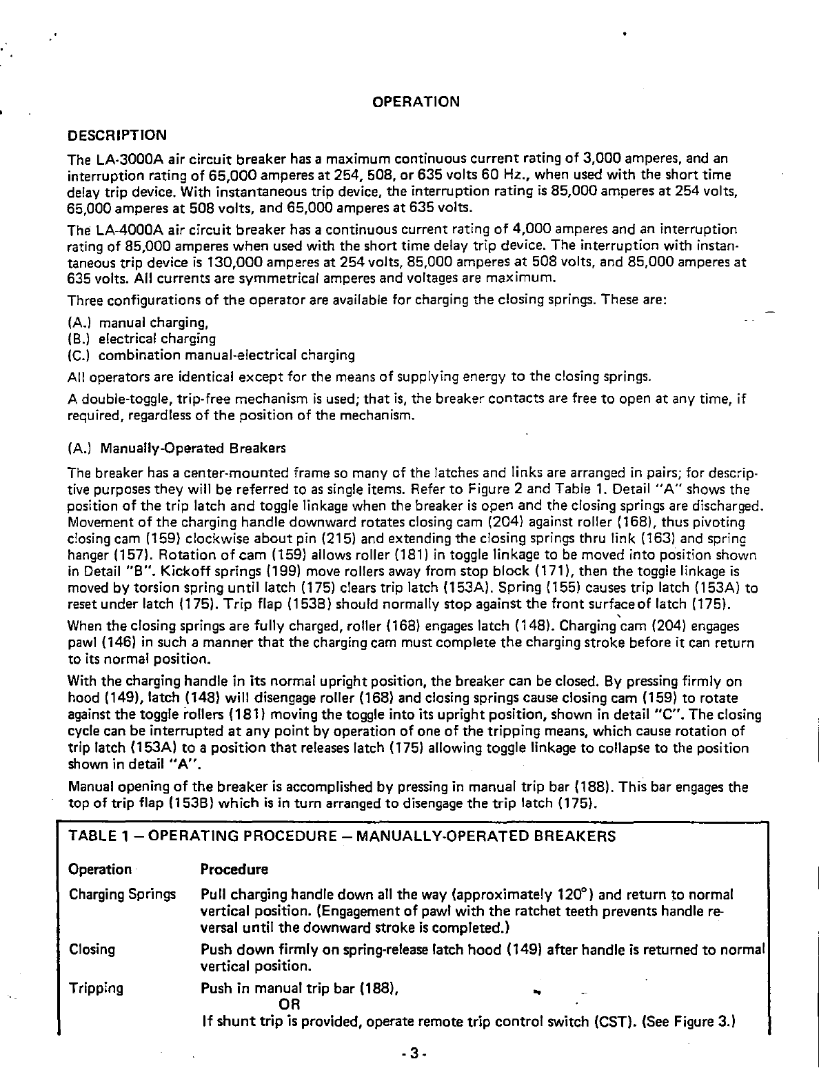
OPERATION
DESCRIPTION
The LA·3000A air circuit breaker has a maximum continuous
current
rating
of
3,000
amperes, and an
interruption rating
of
65,000
amperes
at
254, 508,
or
635 volts
60
Hz., when used with the short time
delay trip device. With instantaneous trip device, the interruption rating
is
85,000
amperes
at
254 volts,
65,000 amperes
at
508 volts, and 65,000 amperes
at
635 volts.
The LA-4000A air circuit breaker has a continuous current rating
of
4,000
amperes and an interruption
rating
of
85,000
amperes
when
used with the short time delay trip device. The interruption with instan·
taneous trip device
is
130,000
amperes
at
254
volts, 85,000 amperes
at
508 volts, and
85,000
amperes
at
635 volts.
All
currents are symmetrical amperes and voltages are maximum.
Three configurations of
the
operator
are available for charging the closing springs. These are:
(A)
manual charging,
(8.) electrical charging
(C.)
combination manual·electrical charging
All
operators are identical
except
for the means
of
supplying energy
to
the
closing springs.
A double-toggle, trip·free mechanism
is
used;
that
is,
the breaker
contacts
are free
to
open
at
any time, if
required, regardless
of
the
position of the mechanism.
(A.) Manually·Operated Breakers
The breaker has a
center·mounted
frame
so
many of the latches and links are arranged
in
pairs; for descrip·
tive purposes they
will
be referred to
as
single items. Refer
to
Figure 2 and Table
1.
Detail
"A"
shows the
position
of
the
trip latch
and
toggle linkage when the breaker
is
open and the closing springs are discharged.
Movement
of
the
charging handle downward rotates closing cam (204) against roller (168), thus pivoting
closing cam (159) clockwise
about
pin (215) and extending
the
closing springs thru link (163) and spring
hanger (157). Rotation
of
cam (159) allows roller (181)
in
toggle linkage to be moved into position shown
in
Detail
"8
".
Kickoff springs (199) move rollers away from stop block (171), then the toggle linkage
is
moved by torsion spring until latch (175) clears trip latch (153A). Spring (155) causes trip latch (153A) to
reset under latch (175).
Trip
flap (1538) should normally stop against
the
front surface
of
latch (175).
When
the
closing springs are fully charged, roller (168) engages latch (148). Charging'cam (204) engages
pawl
(146)
in
such a
manner
that
the charging cam must complete
the
charging stroke before it can return
to its normal position.
With
the charging handle in its normal upright position, the breaker can be closed.
8y
pressing firmly on
hood (149), latch (148) will disengage roller (168) and closing springs cause closing cam (159) to rotate
against
the
toggle rollers (181) moving
the
toggle into its upright position, shown
in
detail
"C".
The closing
cycle can be interrupted
at
any
point
by
operation
of
one
of
the
tripping means, which cause rotation of
trip latch (153A)
to
a position
that
releases latch (175) allowing toggle linkage
to
collapse
to
the position
shown in
detail"
A".
Manual opening
of
the
breaker
is
accomplished by pressing
in
manual trip bar (188). This bar engages the
top
oftrip
flap (1538) which
is
in turn arranged
to
disengage
the
trip latch (175).
TABLE 1 - OPERATING PROCEDURE -MANUALLY·OPERATED BREAKERS
Operation·
Charging Springs
Closing
Tripping
Procedure
Pull charging handle down
all
the way (approximately 120°) and return to normal
vertical position. (Engagement
of
pawl with
the
ratchet teeth prevents handle
re-
versal until
the
downward stroke
is
completed.)
Push
down
firmly
on
spring·release latch
hood
(149) after handle is returned
to
normal
vertical position.
Push in manual trip bar (188),
OR
..
If
shunt
trip is provided, operate remote trip
control
switch (CST). (See Figure 3.)
·3·

(B.) Electrically·Operated Breaker
The mechanism
of
the
electrically operated breaker
is
the
same as
the
manually operated breaker except
that
the manual charging
handle
is
replaced by a
motor
and gear system. Refer
to
Figure 1·2 and 4. With
power available
to
the
control
circuit, closing
the
motor
control switch (MI) will
start
the
automatic
charg.
ing cycle. The
motor
gear
box
pinion rotates gear (224) counterclockwise, cam follower (233) engages an
arm
of
wind and close cam (223) which rotates
the
cams
in
the
same
manner
as for
the
manually
charged.
breaker. When
the
wind
and
close cam (223) reaches its charged position,
the
back
of
the
cam engages
switch lever (229) rotating
the
lever away from
the
switch
operator.
Gear switch lever (231) will still be
holding
the
switch
in
the
operate
position, and the
motor
will
continue
to
run until
the
roll pins on
the
side
of
gear (224) lifts lever (231) clear. releasing
the
motor
cutoff
switch (MCO)' When
the
MCO
switch
opens,
the
motor
stops,
and
the
closing coil circuit
is
set up through
one
side
of
the
MCO
switch.
The breaker can now be closed by depressing the latch hood (149)
or
by
energizing
the
closing coil
(CC)
through
the
external close control switch (CSC). When
the
ClOSE
circuit
is
energized,
the
"Y"
relay
is
energized
and
opens
the
"Y"
contact
in
the
motor
circuit,
thus
preventing
"pumping"
or
repeated at·
tempts
to
charge
the
closing springs.
If
the
close circuit
CSC
switch
is
opened,
the
motor
will automatically recharge the closing springs, if
power
is
available for
the
motor
circuit. The close coil circuit
is
always interrupted by
the
motor
cut·off
switch
MCO.
Trip free
operation
of
the
mechanism, discharging
the
springs on a closed breaker
is
pre·
vented by completing
the
close coil circuit through auxiliary
contact
of
the
breaker.
TABLE 2 - OPERATING PROCEDURE -ELECTRICALLY·OPERATED BREAKERS
Operation
Charging Springs
Closing
Tripping
Procedure
Energize control circuit.
Move
motor control switch on
front
of
breaker
to
"ON"
position.
After
springs are charged, actuate remote close
control
switch (CSC).
OR
Push
down
firmly on spring·release latch
hood
(149).
Actuate
remote trip control switch (CST).
OR
Push in manual trip
bar
(188).
(C.) Combination
Operated
Breaker
The combination manually
and
electrically operated breaker includes
both
the motor·gear charging
system
as
well
as
the
manual charge handle. NOTE: Manual Handle
must
be
in
vertical position during
electrical charging.
Drawout Interlock
The breakers include
as
integral parts
the
mechanism
to
rack
the
breaker
in
or
out
of
the
cubicle compart·
ment, interlocking
to
prevent
racking a closed breaker into
or
out
of
the
connected position, and inter·
locking
to
prevent withdrawing a breaker from
the
cubicle while
the
closing springs are charged.
Racking Mechanism
Refer
to
page 17. With
the
breaker resting on
the
cubicle
rail
the
following sequence should be used
to
rack
the
breaker into
the
cubicle. .
CAUTION!! NEVER INSTALL OR REMOVE A BREAKER FROM THE COMPARTMENT WITHOUT
HAVING
RAIL
EXTENSIONS
IN
PLACE. SEE PAGE 17.
CAUTION!!
ON
ELECTRICALLY OPERATED BREAKERS,
BE
SURE MOTOR CONTROL SWITCH
ON
THE
FRONT
OF THE BREAKER
IS
OFF.
1. Push trip bar in, lower interlock slide
and
insert racking crank.
NOT~
Interlock slide
cannot
be open·
ed unless manual
trip
bar
is
pressed in. While
the
trip bar
is
pressed in,
the
breaker is in
the
TRlp·FREE
position and
cannot
be
closed.
·4·

2. With
the
racking crank,
rotate
the
racking screw (273) until
the
racking
shah
is
in
the
disconnected
position.
The
clevis can
now
engage
the
racking pins (E)
in
the
cubicle.
The
breaker should now be
pushed along
the
rail
into
the
DISCONNECTED position. Double
check
that
the
racking clevis does en-
gage
the
pins
in
the
cubicle.
3. Check
to
see
that
the
floor
interlock (Item 113)
is
clear
before
racking.
4. Counterclockwise
rotation
of
the
racking screw will rack
the
breaker
into
the
TEST
position.
At
the
TEST
position,
the
floor
mounted
interlock
is
clear and
the
cover slide interlock can be closed, allow-
ing
the
trip
bar
to
extend
and
the
breaker can be operated. Between
the
TEST
position and
the
CON-
NECTED position,
the
slide interlock will engage
the
stop pin
and
the
breaker will be tripped through
the
interlock mechanism,
and
the
cover slide
cannot
be closed.
In
the
CONNECTED position,
the
slide interlock will clear
the
stop
pin
of
the
racking toggle and the
floor interlock
is
clear allowing
the
breaker
to
be closed. This prevents moving a closed breaker into
or
out
of
the
CONNECTED position.
5.
To
withdraw
the
breaker
from
the
CONNECTED position,
the
procedure
is
the
same
only
the
racking
screw
rotation
is
clockwise.
6. Before
attempting
to
operate
the
breaker,
the
position
of
the
device should be checked with reference
to
the
marking
in
the
cubicle,
to
be certain
that
it
is
fully
connected.
Two
stop
nuts
are provided on
the
racking screw
to
set
the
connected position. These are adjusted
by
setting
the
angle
of
the
racking
clevis, as shown
in
detail
"0"
of
Figure
1,
and by tightening
the
nuts
against
the
"L"
links (281) the
two
nuts
(278) should
be
then
locked against each other.
CAUTION!! TO AVOID DAMAGE TO THE RACKING MECHANISM,
DO
NOT ROTATE THE RACK-
ING
CRANK
IN
THE COUNTERCLOCKWISE DIRECTION
WHEN
IN
THE CONNECTED
POSITION.
Spring Discharge Interlock
When racking
the
breaker
out
to
the
DISCONNECTED position,
the
closing springs will automatically dis-
charge,
at
or
before reaching
the
disconnect position. The barrel
nut
engages
the
spring interlock. This
in
turn
connects
to
the
manual close
hood
which releases
the
closing springs.
CAUTION!!
ON
MANUALLY CHARGED BREAKERS, THE CLOSE HOOD
IS
INTER LOCKED TO
THE MANUAL CHARGE CAM, AND
MUST
BE
CLEAR BEFORE RACKING THE
BREAKER
TO
THE DISCONNECT POSITION.
NOTE:
Manual charge handle
must
be
in vertical position during racking
and
racking mechanism
must
be returned
to
the
test
position
before
closing springs can
be
charged while
breaker
is
removed from cubicle.
Note also
that
the
spring discharge interlock produces a TRIP-FREE
operation
in which all
of
the
stored
energy
of
the
springs
is
dissipated in
the
mechanism. It
is
preferable
to
turn
the
motor
control
switch
off
in
the
TEST
position, close
the
breaker normally in
that
position,
then
rack
out
in
the
normal manner.
..

MAINTENANCE
AND
ADJUSTMENTS
MAINTENANCE
Occasional checking and cleaning
of
the
breaker
will
promote long and trouble-free service. A
r:
~riodic
inspection
and
servicing, normally
at
intervals
of
one year, should be included
in
the
maintenar:e
routine.
Circuit breakers located
in
areas subject to acid fumes, cement dust,
or
other
abnormal conditi,ms, require
more frequent servicing.
After
a severe overload interruption, the breaker should be inspected.
If the Circuit breaker
is
not
operated during extended periods, it should
not
remain
in
either the closed
or
open position any longer
than
six months. Maintenance opening and closing operations should be made to
ensure freedom
of
movement
of
all
parts.
A suggested procedure to follow during maintenance inspections
is
given below.
1.
De·energize the primary
and
control circuits.
2.
Rack breakers to the disconnected position.
3. Install rail extensions.
4. Remove breaker from cubicle.
5. Remove arc chutes (Figure 1, Item 901) and examine for burned, cracked
or
broken parts. To remove
arc chutes, proceed
as
follows:
a.
Remove wing nuts from holding bar, remove bar and phase barriers.
b. Lift arc chutes vertically
to
clear arc runners.
6.
Wipe
the
contacts with a clean cloth saturated with a non-toxic cleaning fluid.
7.
Replace badly burned
or
pitted
contacts. (See Contact Replacement, Page 8, and Lubrication Instruc·
tions, Pages 6 and 21.)
8. Wipe all insulated parts with a clean cloth saturated with a non·toxic cleaning fluid.
9. Bearing pins and other sliding
or
rotating surfaces should be cleaned and then coated with a light film
of
grease. (See Lubrication chart page 21.:
10. Charge the breaker manually for maintenance closing
(see
Maintenance Closing belQw)
to
check
latch and linkage movement. (Rotate racking screw to the approximate
test
position to clear spring
dump interlock before
attempting
to change closing springs.)
11. Check breaker adjustments (see Adjustments,
Page
7).
LUBRICATION
Lubrication should be a
part
of
the
servicing procedure. Old grease should be removed from bearing pins
and
other
non-current carrying rotating
or
sliding surfaces, and they should be wiped with a thin film of
petroleum-oil-base precision·equipment grease, such
as
BEACON
P·290.
Greasing should be done with care so
as
to
avoid getting on insulating members, since it may affect the
dielectric strength. Faces
of
main and arcing contacts should
not
be lubricated. The rubbing surfaces
of
the
main
contact
fingers and hinge
contact
fingers are lubricated with coating
of
A-C
contact
lubricant,
15-171·370-002. If dust has accumulated, disassembly
is
necessary
to
clean and relubricate these points.
(See Contact Replacement, Page 8, and Lubrication Instructions,
Page
21).
MAINTENANCE CLOSING
During inspect:on prior to insta'lation and for routine maintenance inspections, the breaker contacts may
be closed slowly
to
check clearances,
contact
adjustments, and movement
of
links and latches. A manual
charging handle
is
used for maintenance closing the breaker.
Electrically-op~rated
breakers
do
not
have a marual charging handle,
but
it
is
available
as
a maintenance
item. Figure 5 shows the charging handle installed
in
an
electrically-operated breaker
after
removal
of
the front cover from the breaker. When
the
hole
in
t;e
charging handle assembly
is
aligned with
the
holes
in
the
operating mechanism frame,
the
pin which
is
attached
to
the
cam is inserted. This pin holds
the
assembly in place and acts as a pivot
point
for the cam. After installation
of
the
manual charging
-6-
l
..
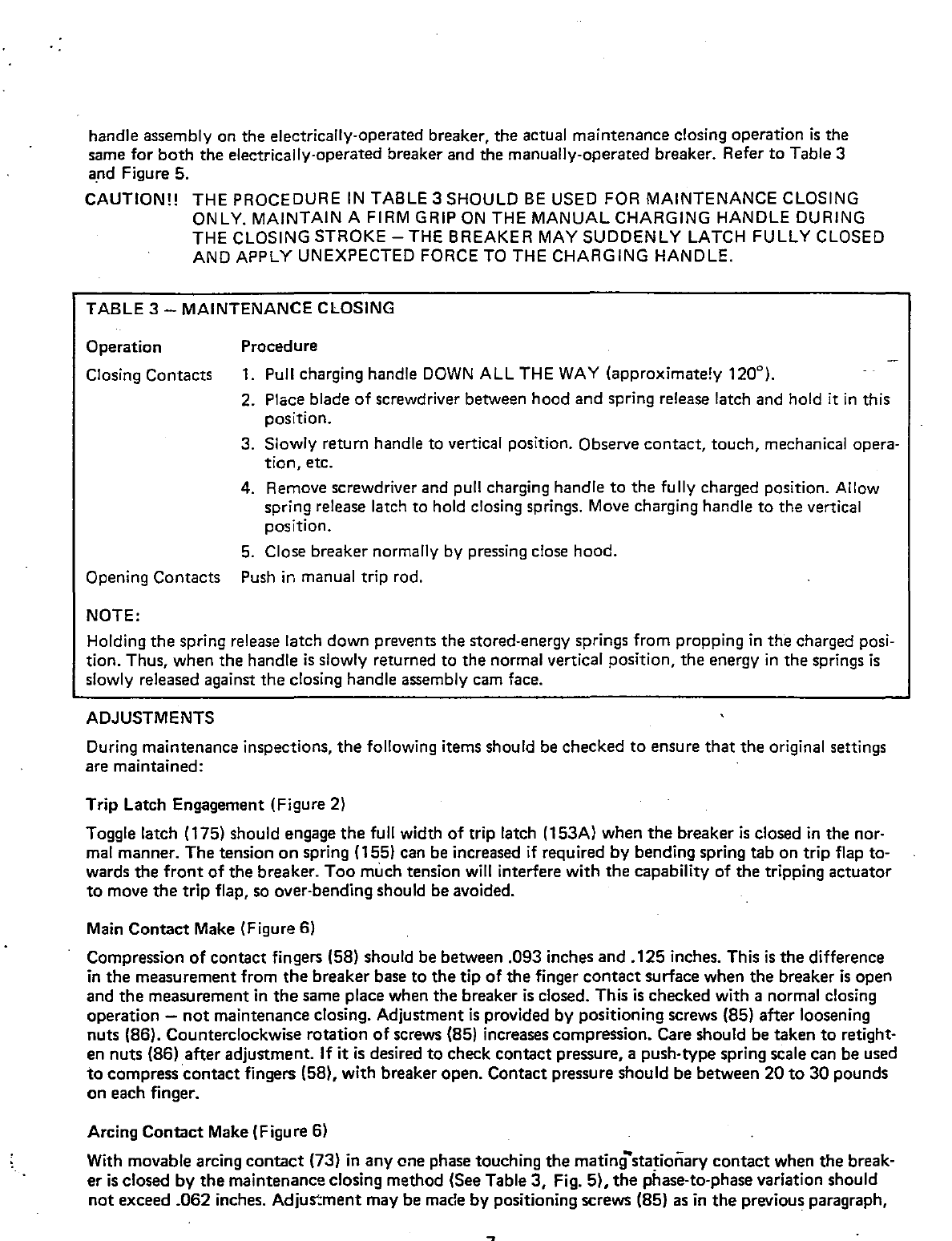
handle assembly on the electrically-operated breaker, the actual maintenance closing operation
is
the
same for
both
the electrically-operated breaker and the manually-operated breaker_ Refer
to
Table 3
and Figure 5.
CAUTION!! THE PROCEDURE
IN
TABLE 3 SHOULD
BE
USED FOR MAINTENANCE CLOSING
ONLY. MAINTAIN A FIRM GRIP
ON
THE MANUAL CHARGING HANDLE DURING
THE CLOSING STROKE -THE BREAKER
MAY
SUDDENLY
LATCH
FULLY CLOSED
AND
APPLY UNEXPECTED FORCE
TO
THE CHARGING HANDLE.
TABLE 3 - MAINTENANCE CLOSING
Operation Procedure
Closing Contacts 1. Pull charging handle
DOWN
ALL THE
WAY
(approximate!y 120°),
2. Place blade
of
screwdriver between hood and spring release latch and hold it
in
this
position.
3. Slowly return handle to vertical position. Observe contact, touch, mechanical opera-
tion,
etc.
4. Remove screwdriver and pull charging handle
to
the fully charged position. Allow
spring release latch to hold closing springs. Move charging handle
to
the vertical
position.
5. Close breaker normally by pressing close hood.
Opening Contacts Push
in
manual trip rod.
NOTE:
Holding
the
spring release latch down prevents the stored-energy springs from propping
in
the charged posi-
tion. Thus, when the handle
is
slowly returned to the normal vertical position,
the
energy
in
the
springs
is
slowly released against
the
closing handle assembly cam face.
ADJUSTMENTS
During maintenance inspections,
the
following items should be checked
to
ensure
that
the
original settings
are maintained:
Trip Latch Engagement (Figure 2)
Toggle latch (175) should engage
the
full width
of
trip latch (153A) when
the
breaker
is
closed
in
the nor-
mal manner. The tension
on
spring (155) can be increased
if
required
by
bending spring tab on trip flap to-
wards the
front
of
the breaker.
Too
much tension
will
interfere with
the
capability of the tripping actuator
to
move
the
trip flap,
so
over-bending should be avoided.
Main
Contact
Make (Figure 6)
Compression
of
contact fingers
(5B)
should be between .093 inches and
.125
inches. This
is
the
difference
in
the
measurement from
the
breaker base to
the
tip
of
the finger
contact
surface when the breaker
is
open
and
the
measurement
in
the
same place when the breaker
is
closed. This
is
checked with a normal closing
operation -
not
maintenance closing. Adjustment
is
provided by positioning screws (85) after loosening
nuts (86). Counterclockwise rotation
of
screws (85) increases compression_ Care should be taken
to
retight-
en nuts (86) after adjustment. If
it
is
desired
to
check contact pressure, a push-type spring scale can be used
to
compress'contact fingers (58), with breaker open. Contact pressure should be between
20
to
30
pounds
on each finger.
Arcing
Contact
Make (Figure 6)
With movable arcing
contact
(73) in
anyone
phase touching the mating"stationary
contact
when the break-
er
is
closed
by
the
maintenance closing method (See Table
3,
Fig. 5).
the
phase-to-phase variation should
not
exceed
_062
inches. Adjus:ment may be made by positioning screws (85)
as
in
the
previous paragraph,
..

but
it
is
essential
that
the main
contact
compression be maintained within
the
tolerance listed
in
the
pre-
vious paragraph. Arcing
contact
pressure should be between
20
and
30
pounds when checked with a pull-
type spring scale
at
the
base
of
the arcing contact tip insert with the breaker contacts closed. Measure each
blade separately.
Contact Replacement
(F
igu
re 6)
The
contact
structure consists
of
main current carrying contacts and arcing contacts arranged so
that
initial
contact make and final
contact
breaker
is
by means of the arcing contacts. The actual
contact
surfaces are
clad with an alloy facing which greatly reduces mechanical
w~ar
.and arc erosion.
When
inspection
of
the
alloy facing indicates that the contacts should be replaced, it should be noted
that
hinge
contact
fingers (66, 67) main
contact
fingers (70) and arcing contacts (73) are spring loaded. There-
fore, care
must
be exercised
in
removal and installation of any
of
the contacts.
Main
Contact
Fingers (Figure 6)
With
the
breaker contacts open and the stored-energy springs discharged, main
contact
fingers (58) may be
removed by loosening screws (75) enough to relieve the compression on springs (54, 57). There are two
springs behind each finger and it
is
important that they be positioned properly upon reinstallation.
If
diffi-
culty
is
experienced
in
correctly positioning these springs, the upper and lower primary disconnects (902,
Figure
1)
may be removed from each phase and the breaker inverted
to
rest on the ends
of
connectors (52)
and (62).
Stationary Arcing Contact (Figure 6)
The stationary arcing
contact
is
part
of
connector (52) and may be replaced by proceeding
as
above.
In
this
case, screws (60) must be removed.
Hinge
Contact
Fingers (Figure 6)
Hinge
contact
fingers can be replaced by removing lower connector and removing fingers individually.
Moving Arcing
and
Main
Contact
(Figure 6)
Either moving arcing
contact
(73)
or
main contact (70) or both may be removed and replaced
as
follows:
Remove
two
screws on each side
of
lower connector. The complete movable
contact
assembly may now be
brought
to
a bench_ The location
of
spacers should be noted,
in
disassembly.
CAUTION!! EXTREME CARE SHOULD
BE
TAKEN
TO
HOLD
THE ASSEMBLY FIRMLY TO
RE-
TAIN SPRING GUIDE (80)
AND
SPRING
(82,83)
UPON REMOVAL OF THE SCREWS.
The moving arcing
contact
or
the
main contact may now be easily repli'lced. The reverse procedure
is
fol-
lowed for re-installation. Care should be taken
to
replace spacers correctly. Check alignment and adjust-
ment
of
contacts
upon
reassembly.
T ripping
Actuator
When
the
static trip device senses a circuit condition
that
requires
the
circuit breaker
to
open,
it
produces
an
output
that
is fed
to
the
tripping actuator. This device then causes
the
circuit breaker contacts
to
open
and isolate
the
circuit.
Mounted
on
the
circuit breaker,
the
tripping actuator
is
held
in
a charged position
by
a permanent magnet.
It contains a coil
that
is
energized
by
the
output
of
the
static trip device. When energized,
the
coil causes
the
magnetic flux
to
shift
to
a new
path,
releasing the stored energy
of
a spring located inside the tripping
actuator. The spring provides
the
energy
to
trip the breaker moving
the
trip flap clear
of
the
toggle latch.
If
the
spring loaded armature does
not
reset during trip operation as explained above, spacer washers may
be added
to
obtain positive reset
of
the
armature. ..
If
adding spacers does
not
allow
the
armature
to
be reset,
the
tripping actuator should be replaced (if break-
er mechanism
is
not
at
fault)_
_R -
NOTE:
Do
not
attempt
to
disassemble
the
tripping
actuator
as
this may
destroy
the
magnetic field set-up by
the
permanent
magnet
and
will render
the
actuator
latch inoperative until remagnetized.
When replacing a tripping actuator,
the
coil leads must be connected
to
the
terminal block
of
the
static
trip in
the
correct
polarity relationship.
The black lead
of
coil
must
be
connected
to
terminal 7 (negative)
and
the
red lead
of
coil connected
to
terminal 8 (positive)
of
the
static trip device.
When
the
tripping
actuator
has been replaced,
the
circuit breaker should be given a FUNCTION TEST
to
ensure
proper
operation
of
all
components.
Refer to Allis-Chalmers Instruction Book 18X4827-02 for
the
procedures
of
the
FUNCTION TEST.
Motor
Cutoff
Switches
The
function
and
adjustment
of
the
motor
cutoff
switches
on
electrically-operated breakers
is
described on
Page
10_
..
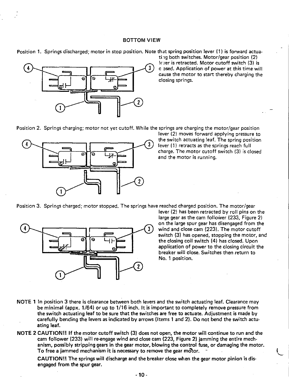
Position 1.
Position 2.
BOTTOM
VIEW
Springs discharged; motor
in
stop position. Note
that
spring position lever (1)
is
forward actua·
t;:,g both switches. Motor/gear position (2)
Iner
is
retracted. Motor
cutoff
switch
(3)
is
c osed. Application
of
power
at
this time
will
cause
the
motor
to
start
thereby charging the
closing springs.
Springs charging;
motor
not
yet cutoff.
Wh
ile
the springs are charging the motor/gear position
e e
lever (2) moves forward applying pressure to
the
switch actuating leaf. The spring position
lever
(1)
retracts
as
the springs reach full
charge.
The.motor
cutoff
switch
(3)
is
closed
and the
motor
is
running.
Position 3. Springs charged;
motor
stopped. The springs have reached charged position. The motor/gear
lever (2) has been retracted by roll pins on the
large gear
as
the
cam follower (233, Figure 2)
on
the large
spur
gear has disengaged from the
wind and close cam (223). The
motor
cutoff
switch (3) has opened, stopping
the
motor, and
the
closing coil switch (4) has closed. Upon
application
of
power
to
the
closing circuit the
breaker will close. Switches then return
to
No.1
position.
NOTE 1
In
position 3 there
is
clearance between both levers and the switch actuating leaf. Clearance may
be minimal (appx. 1/64)
or
up
to
1/16
inch. It
is
important
to
completely remove pressure from
the
switch actuating leaf
to
be sure
that
the
switches are free
to
actuate. Adjustment
is
made by
carefully bending
the
levers as indicated by arrows (Items 1 and 2). Do
not
bend
the
switch actu-
ating
leaf_
NOTE 2 CAUTION!! If
the
motor
cutoff
switch (3) does not open,
the
motor
will continue
to
run and the
cam follower (233) will re-engage wind and close cam (223, Figure 2) jamming
the
entire mech-
anism, possibly stripping gears
in
the
gear motor, blowing the control fuse,
or
damaging
the
motor.
To
free a jammed mechanism
it
is
necessary
to
remove
the
gear
m~or.
CAUTION!! The springs
will
discharge and
the
breaker close when
the
gear
motor
pinion is dis-
engaged from
the
spur
gear.
-
10-
(
'-...
ACCESSORIES
Tripping Transformers -Static Trip
II
There are several tripping transformer ratings available, each with seven calibrated pickup settings (Page 12).
The tripping transformers are mounted on the lower connector and mounted with the polarity mark facing
the breaker panel.
Current
Sensors -LimiTrip
The
current
sensors provided with the optional LimiTrip device are integrated units containing two cores
with four terminals. Proper polarity
is
established when the terminals face away from the panel. LimiTrip
sensors should never be subjected to primary current with the LimiTrip device disconnected from the
sensor.
OPTIONAL DEVICES
Secondary Disconnect Assembly Option
The electrical
attachments
are wired
to
the
terminals
of
a secondary disconnect assembly (See Figure 7).
which
is
mounted
on
the
left side
of
the
breaker. Three blocks
of
ten terminals each can be mounted on
the breaker.
The
secondary disconnect assembly
is
accessible from
the
front of the breaker and aligns with
a stationary
unit
in
the
cubicle. The stationary contact strips should be lubricated with a light film
of
con·
tact grease which
is
furnished with
the
switchgear.
Atfxiliary Switch
Option
The auxiliary switch (See Figure
8)
is
of
the rotary type and functions by direct connect
to
the
breaker
mechanism.
The
contacts are factory set for
"a"
(open when the breaker
is
open) and
"b"
(closed when
the breaker
is
open) position,
but
each rotor (955) may be adjusted individually
in
steps
of
30
degrees. This
adjustment
is
made by removing cover (962) and lifting the entire
rotor
assembly
out
of case (950) after
disconnecting arm (957) from
the
linkage. Cotter pin and bearing (956) are removed to permit
reo
moval
of
rotors (955) from shaft (954). To change rotors (955) from
"a"
to
"b"
position,
the
rotor should
be
rotated 60°
in
the
clockwise direction after removal and replaced on the shaft
in
this new position.
Shunt
Trip
Option
Each electrically·operated breaker
is
equipped with a
shunt
trip attachment for tripping from a remote
location. (See Figure 9). Since the
shunt
trip coil
is
designed for a momentary
duty
cycle, an
"a"
auxiliary
contact switch
is
used
to
interrupt
its circuit immediately after
the
breaker
is
tripped. Energization
of
the
coil causes
the
armature
to
pick up and rotate the trip latch
to
trip
the
breaker. A compression spring (808)
returns
the
armature
to
its normal position.
Undervoltage Trip Device Option
The undervoltage
trip
device (Figure 10) automatically trips the breaker on loss of voltage. Either instan·
taneous
or
time·delay operation can be supplied. A .06 inches
gap
should be maintained between flap ex·
tension and pull link (738) when
the
device
is
energized with the breaker closed. Pick·up and drop-out
is
set so
that
the
device picks up
at
a voltage of 85%
or
less
of rated value and drops
out
between 30% and
60%
of
the
rated value.
NOTE:
Pick-up and
drop-out
are
not
individually adjustable.
Bell
Alarm Switch
Option
The bell alarm switch
option
(See Figure 11) functions
to
operate a switch. A single pole double
throw
or
a double pole
double
throw
switch
is
available. The switch operator
is
connected
to
and
is
operated by the
tripping
actuator.
The
switch operator remains tripped even when
the
actuatorJs reset
by
the
breaker. The
switch
operator
must
be reset either manually,
or
by an additional optional electrical reset solenoid.
The
contacts
of
the
bell alarm switch can be connected
in
series with
the
hreaker closing coil,
to
provide a
lockout feature
to
prevent reclosing after a fault.

TABLE 4 - TRIP RATING TABLE -AMPERES
STATIC TRIP
II
Breaker Tripping Long Time Element Ground Element
Type and XFMR Calibrated Pick-Up Settings
Max_
Calibrated Pick-Up
Frame Rating E Cont_ Settings
Size (Primary) A C D E F G Rating 15%
25%
50% 100%
LA-3000A 2000 Amps 1000 1250 1500 1750 2000 2250 2500 2500
300
500
1000 2000
LA-30OOA
3200
Amps 1600 2000 2400 2800
3200 3600
4000
3000
480
800
1600 3200
LA-4000A
4000
Amps
2000
2500 3000
3500
4000 4500
5000
4000
600
1000 2000 4000
TABLE 5 - TRIP RATINGS -AMPERES.
LlMITRIP
Breaker Tripping Long Time Element
Type and XFMR Calibrated Pick-Up Settings Max.
Frame Rating Cant.
Size (Primary) A B C D E F Rating
LA-3000A
2000
Amps 1000 1250 1500 I 1750 2000 2250 2500
LA-3000A
3200
Amps 1600 2000 2400
2800
3200
3600
3000
LA-4000A
4000
Amps 2000 2500
3000
3500
4000
4500
4000
Static Trip
Option
The optional tripping devices are covered
in
detail under their own instruction books which are referenced
on the last page. Several
types
are available
that
provide a range
of
tripping functions.
The Static Trip
II
device
mounts
onto
a slide type bracket
on
the
circuit breaker.
To
remove trip device,
the terminal block cover located above the trip device should be removed, exposing
the
terminal block
screws. The lower row
of
screws can be loosened with a screwdriver, allowing
the
terminal block fanning
strip from
the
static
trip
to
be
removed from
the
terminal block. Removal
of
the fanning strip exposes a
mounting screw. This screw can be removed allowing the static trip device
to
be removed from the breaker
by pulling the
trip
device towards
the
front
of
the
breaker.
_
1")
_

273
-:..l
I 902
DETAIL
"0"
@
.~~
-"
,,
"
,\
:l
'~--i'
I
¥l
, "
I
::.
, ,
I
I',
I " ),
I '1/'
.
J.:
I
I
~".I..
I
·~"'--'ir·J
to
~
~f~~-""""='~-""!-'"
-~t.:
0 : 0 I"
'1':~~
t
~
~:
LH
SIDE
VIEW
B
I 901
12-1.
______
...
-----
-:r
"-4
~Jj
_902
o o @
o 0 o
RH
SIDE
VIEW
C
Fig. 1 - LA·3000A Circliit Brenl<er
240
241
~
FRONT
VIEW
A
SECTION "AA"
k
241
240
,",
,,
,,
,,
,0

DETAIL
"A"
\
1S3A
DETAIL
"US"
DETAIL
"C"
~,
11
171
1538
VIEWCC
231
~
168
VIEWAA
VIEW
EE
199
o
LH
SIDE
VIEW
149
['--
--~~
I~,:
/'48
,
204
'~"
\
~.
'
..
..,
.
'"
:::
J
~
~<~l\~
~"
,:~
~rr
.
\.1':
1T"l~
l1lt1:,~
DETAIL G -
157
f=i~h",.:J!
188
FRONT
VIEW
223
ij
~=
VIEW
FF
kllf~
233
rr=-fl
V
'-I
224
~~g;;;m,,=
''1Ilr"
VIEWHH
Fig. 2 - Operator
:111
1
~
181
~
.!t
VIEWDD
\
175
r,,,.,ommm",
''''
. \
113

'.
-~--------------------~--1---
I I I
I
I
I
I
I
I
I
I
I
I
SUPPLY
L[:1r-r---,--------
I I
I
~,~.
I
I
esc
II
II
~CST
I J.:
L,J;r.
T
I T
('G',
,
R'1
I
I I
\..1'
\....
I
l~
I
l!-
L_
~
3
4 Y
3A
1
2
8 )
BR'KR.
&)
f
CaNTACT~
13
HII
C.T. I
1
'-;...."r
88
y
88·2
12
7 2 7A
~4
1
sl
1 b
MI
6 1 a
6~9
2l:==='-
__
b=:::::!.
8
2;
~
y~
,
I I
STO
STATIC
TRIP
DEVICE
r-rr:]}-----------J...----
:
-~--------------------
..
--
AS
.r
r
fS.r
SO
f
bxat
2 4 6 8
10
AUX. SWITCH
cgv
"8V
"7'-'
<>sv
7
o-:-v
"3'v
~
~
<>-'-v
SEC. DISC.
SYMBOLS
CC
-
CIRCUIT
BREAKER CLOSING
COIL
TC -
CIRCUIT
BREAKER
TRIP
COIL
Y -
AUX.
CLOSING
RELAY·
ANTI
PUMP
MCO -MOTOR CUTOFF SWITCH
88 -SPRING CHARGING MOTOR
CSC
-CONTROL SWITCH· CLOSE
CONTACT
CST -CONTROL SWITCH· TRIP
CONTACT
R - RED INDICATING LAMP
G -GREEN INDICATING LAMP
• -
AUX,
SWITCH·
OPEN
WHEN
8R'KR.
IS OPEN
b -
AUX.
SWITCH -CLOSED WHEN
BR'KR.
IS OPEN
MI -
MECHANICAL
INTERLOCK
CT
-CURRENT TRANSFORMER .
STD -STATIC TRIP DEVICE
AL
-
ALARM
DEVICE
RC -
ALARM
DEVICE ELECT. RESET
COIL
TA
-
TRIP
ACTUATOR
~
UV
-UNDERVOLTAGETRIPCOIL
CLASS C WIRING
NO. 14 WIRE, (SISI
00·557·286·341
Mca
BL
1
tJ
~
1~
~1P
~~
<S2
2
Fig, 3 - Typical Wiring Diagram -Electrically Operated Breakers
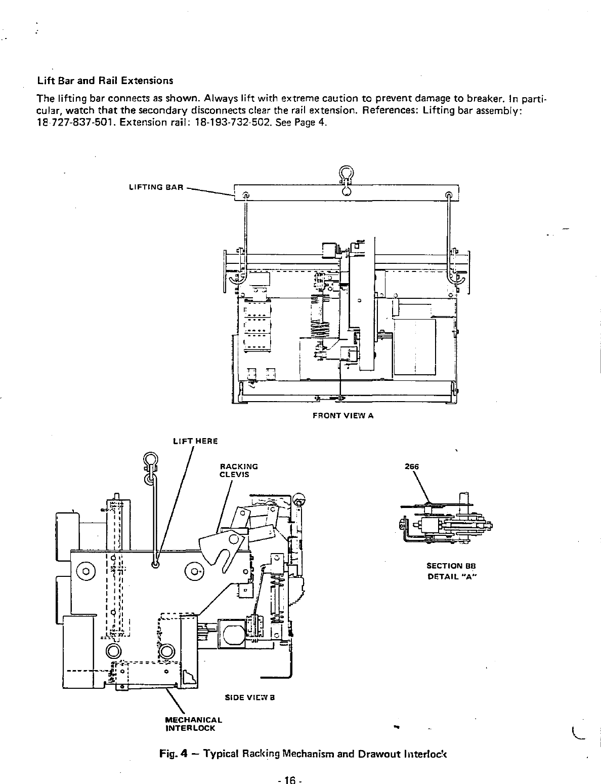
Lift Bar
and
Rail Extensions
The
lifting
bar
connects as
shown.
Always lift with extreme caution
to
prevent damage
to
breaker.
In
parti·
cular, watch
that
the
secondary
disconnects clear the
rail
extension. References: Lifting bar assembly:
18
727·837
·501. Extension rail: 18·193·732-502. See
Page
4.
-~~
"
1----1"
..
,)
,;
LIFTING
BAR
--
__
I
LIFT
HERE
MECHANICAL
INTERLOCK
SIDE
VIEWS
FRONT
VIEW
A
266
SECTION
BB
DETAIL
"A"
Fig. 4 - Typical Racking Mechanism
and
Drawout
Illterloc'<
.
16
.
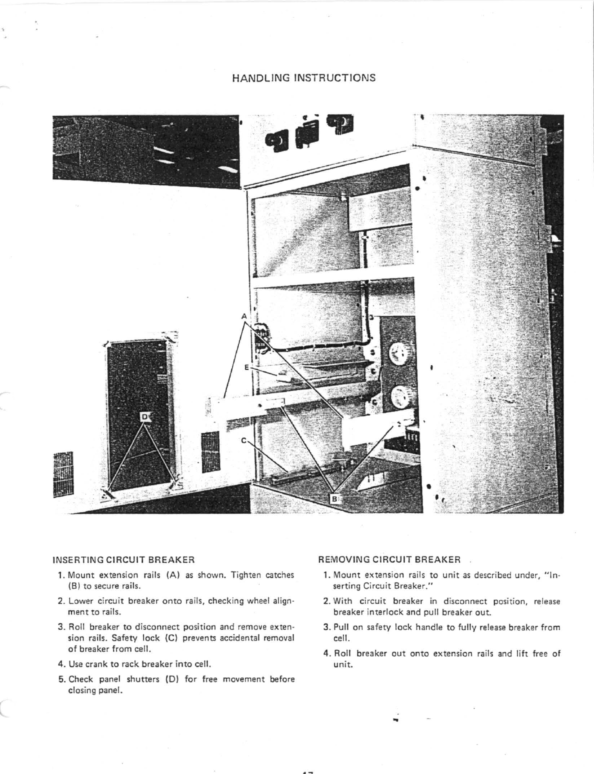
HANDLING
INSTRUCTIONS
I
INSERTING
CIRCUIT
BREAKER
1. Mount extension rails (A) as shown. Tighten catches
(8) to secure rails.
2. Lower circuit
breaker
onto
rails, checking wheel align-
ment
to
rails.
3. Roll breaker
to
disconnect
position
and
remove exten-
sion rails. Safety
lock
(e)
prevents accidental removal
of
breaker from cell.
4.
Use
crank
to
rack
breaker
into
cell.
5. Check panel
shutters
(0)
for
free movement before
closing panel.
REMOVING
CIRCUIT
BREAKER
1.
Mount
extension
rails
to
unit
as
described under,
"in-
serting Circuit Breaker,"
2. With
circuit
breaker
in
disconnect position, release
breaker i
nterlock
and pull breaker
out.
3. Pull on safety lock handle
to
fully release breaker from
cell.
4.
Roll breaker
out
onto
extension rails and
lift
free
of
unit.
This manual suits for next models
1
Table of contents
Other Siemens-Allis Circuit Breaker manuals


Popular Circuit Breaker manuals by other brands


Moeller
Moeller NZMS 4 Series installation instructions

Allen-Bradley
Allen-Bradley Guardmaster 442G-MABR-URM-C03 manual

IDEAL
IDEAL 61-534EU Staff Quick Start Guide

GE
GE AM-4.16-250-6 instructions

Eaton
Eaton IL047011ZU Instruction leaflet

GTE SYLVANIA
GTE SYLVANIA SSPB 800 Installation, operating, & maintenance instructions

Allen-Bradley
Allen-Bradley 140M-C-AFA Series Installation instruction

WEG
WEG AGW650 quick start guide

Siemens
Siemens CDT3A Series operating instructions

DCC Specialties
DCC Specialties PS 1 Series manual

GE
GE AM-13.8-750-4C INSTRUCTIONS AND RECOMMENDED PARTS FOR MAINTENANCE

Eaton
Eaton RASP5 EIP Series Original operating instructions