Siemens-Allis R Series Guide


CONTENTS
TABLE
OF
CONTENTS
Introduction
General
Warranty
General
Description
Foundation
General
Indoor
Outdoor
Weights
of
Cubicles
Receiving
and
Handling
General
Identification
Inspection
and
Uncrating
Lifting
Switchgear
Use
of
Rollers
and
Jacks
Storage
Indoor
Switchgear
Outdoor
Switchgear
Installation
Introduction
Installing
Shipping
Sections
Setting
Shipping
Sections
Plumbing
and
Leveling
Instructions
Plumbing
Leveling
Indoor
Switchgear
Leveling
Outdoor
Switchgear
Installation
of
Traveling
Crane
Safety
Warning
Cleaning
Electrical
Connections
Primary
Connections
Bolted
Bus
Joints
Hardware
Note
Connection
to
Power
Transformer
Primary
Cable
Connections
Current
Transformers
Ground
Connections
Optional
Devices
Shutters
(
MOC
)
Switches
(
TOC
)
Switches
Key
Interlock
Drip
Resistant
Switchgear
(
Indoor
Option
)
Switchgear
Expanding
General
Indoor
Switchgear
Outdoor
Switchgear
Breaker
Preparation
and
Insertion
Preparation
Compartment
Identification
Placing
Breaker
in
Compartment
Racking
Breaker
Handling
Instructions
Drawout
Fuse
Carriage
(
3200
Amp
and
4000
Amp
)
Future
Breaker
Compartments
Inspection
and
Testing
Before
Energising
General
Inspection
Testing
Inspection
and
Testing
Before
Operation
Current
Transformers
Secondary
Load
Circuits
Control
Circuits
Watt
Meters
,
Watt
-
Hour
Meters
and
Directional
Relays
Static
Overcurrent
Trip
Devices
High
Potential
Tests
Phasing
-
Out
Maintenance
General
Time
Interval
Inspection
Cleaning
Insulation
—
Caution
Lubrication
Wiping
Electrical
Contacts
Mechanical
Devices
Circuit
Breakers
Relays
and
Instruments
Equipment
Surfaces
19
1
21
2
22
2
23
3
23
3
23
3
4
24
25
5
25
5
25
5
26
5
6
27
27
8
8
28
28
9
28
10
11
29
11
29
11
29
11
11
29
12
29
12
29
12
29
13
31
13
31
13
31
14
31
15
31
17
32
17
32
32
18
32
19
32
Courtesy of NationalSwitchgear.com

r
INTRODUCTION
Page
1
A
DANGER
GENERAL
This
manual
contains
instructions
for
receiving
,
handling
,
storage
,
installation
,
inspection
,
testing
and
maintenanceof
Siemens
-
Allis
low
voltage
metal
-
enclosed
switchgear
.
The
switchgear
described
herein
consists
of
the
600
volt
class
indoor
and
outdoor
designs
.
The
contents
of
this
manual
are
applicable
to
all
"
R
”
and
“
SR
”
switchgear
classes
arid
designs
unless
noted
otherwise
.
Siemens
-
Allis
low
voltage
switchgear
carries
letter
designations
as
follows
:
“
R
”
for
indoor
and
“
SR
”
for
outdoor
walk
-
in
(
NEMA
3
R
)
equipment
.
These
designations
may
appear
on
drawings
and
other
media
,
and
familiarity
with
them
will
simplify
communication
with
the
factory
.
Figures
1
and
2
show
typical
installations
.
Standard
construction
details
of
necessary
auxiliary
and
accessory
equipment
are
included
in
appropriate
sections
.
Instructions
for
spe
-
cial
mechanical
and
electrical
devices
,
as
specified
in
the
purchase
order
,
are
covered
by
supplementary
data
sub
-
mitted
with
this
instruction
manual
.
Ratings
described
in
this
manual
are
in
accordance
with
NEMA
,
IEEE
and
ANSI
standard
requirements
.
(
This
equipment
is
listed
with
Underwriters
Laboratories
,
Inc
.
)
Due
to
the
nature
of
this
product
,
there
is
inherent
danger
in
its
use
through
possible
exposure
to
high
electrical
voltage
.
Only
qualified
persons
thoroughly
familiar
with
these
instructions
should
be
allowed
to
operate
these
devices
.
Improper
use
or
procedures
can
result
in
serious
personal
injury
or
death
.
^
DANGER
No
attempt
to
operate
this
equipment
should
be
undertaken
without
fully
reading
the
instruction
manual
.
Operators
must
be
familiar
with
the
equipment
,
its
operation
,
and
have
read
these
instructions
prior
to
each
use
.
Failure
to
do
so
result
in
electrical
shock
or
burn
causing
may
death
or
serious
personal
injury
and
property
damage
.
Use
of
the
Siemens
-
Allis
equipment
must
be
restricted
to
qualified
personnel
.
A
qualified
person
is
one
who
is
familiar
with
the
installa
-
tion
,
construction
or
operation
of
the
equipment
and
the
hazards
involved
.
In
addition
,
this
quali
-
fied
person
has
the
following
qualifications
:
Is
trained
and
authorized
to
de
-
energize
,
clear
ground
and
tag
circuits
and
equipment
in
accor
-
dance
with
established
safety
practices
.
Is
trained
in
the
proper
care
and
use
of
protective
equipment
such
as
rubber
gloves
,
hard
hat
,
safety
glasses
or
face
shields
,
flash
clothing
,
etc
.
,
in
accordance
with
established
safety
practices
.
Is
trained
in
rendering
first
aid
.
Figure
1
.
Picture
of
Typical
Low
Voltage
Indoor
Switchgear
Group
,
Type
“
R
”
Courtesy of NationalSwitchgear.com
INTRODUCTION
Page
2
WARRANTY
GENERAL
DESCRIPTION
For
warranty
coverage
,
see
sales
contract
.
Equipment
furnished
has
been
designed
to
operate
in
a
system
having
the
circuit
capacity
specified
by
the
purchaser
.
If
for
any
reason
the
equipment
is
used
in
a
different
system
,
or
if
short
-
circuit
capacity
of
the
system
is
increased
,
a
check
must
be
made
of
the
rating
of
the
switchgear
,
the
interrupt
-
ing
capacity
of
the
circuit
breakers
and
the
bus
capacity
.
Failure
on
the
part
of
the
user
to
obtain
approval
of
intended
changes
from
Siemens
-
Allis
may
be
cause
for
voiding
the
warranty
.
The
switchgear
described
in
this
manual
is
of
the
metal
-
enclosed
type
.
The
cubicles
described
are
comprised
of
full
depth
side
sheets
and
components
segregating
breaker
compartments
from
the
bus
section
,
from
each
other
and
from
compartments
containing
auxiliary
sec
-
ondary
equipment
.
In
addition
,
the
cubicle
and
intercubi
-
cte
bus
work
may
be
shielded
(
optional
)
from
the
primary
entrance
cable
area
with
segregating
barriers
.
Interlocks
are
provided
,
where
necessary
,
to
insure
proper
sequence
and
safe
operation
.
Indoor
switchgear
,
type
“
Ft
”
,
consists
of
one
or
more
cubi
-
cles
secured
together
as
a
single
group
.
It
is
completely
operational
when
installed
and
connected
to
customer
’
s
power
supply
.
When
connected
directly
to
a
power
trans
-
former
a
14
”
(
355.6
mm
)
wide
transition
section
may
be
provided
to
adjust
connections
to
the
proper
elevation
or
provide
space
for
incoming
metering
current
transformers
.
Circuit
breaker
compartments
are
provided
with
hinged
access
doors
for
installing
or
removing
circuit
breakers
.
Auxiliary
compartmentsare
designed
with
hinged
panels
for
mounting
of
instruments
,
relays
and
switches
.
Outdoor
switchgear
,
type
“
SR
”
,
is
similar
to
indoor
switch
-
gear
,
except
that
it
is
enclosed
in
a
weather
resistant
(
NEMA
3
R
)
steel
housing
.
The
equipment
is
designed
so
that
weather
conditions
will
not
affect
operation
of
the
switchgear
.
An
illuminated
service
aisle
is
provided
at
the
front
of
the
switchgear
allowing
inspection
and
mainte
-
nance
without
exposure
to
the
elements
.
An
access
door
is
provided
at
each
end
of
the
aisle
wall
with
panic
bar
latch
release
inside
the
aisle
.
The
rear
of
each
cubicle
is
equipped
with
a
door
for
access
to
the
primary
cable
entrance
area
and
secondary
terminal
blocks
.
These
doors
and
all
external
covers
are
secured
with
tamper
-
resistant
screws
.
Special
1
/
4
"
-
drive
sockets
for
these
screws
are
shipped
with
the
accessories
(
Part
No
.
15
-
171
-
404
-
051
)
.
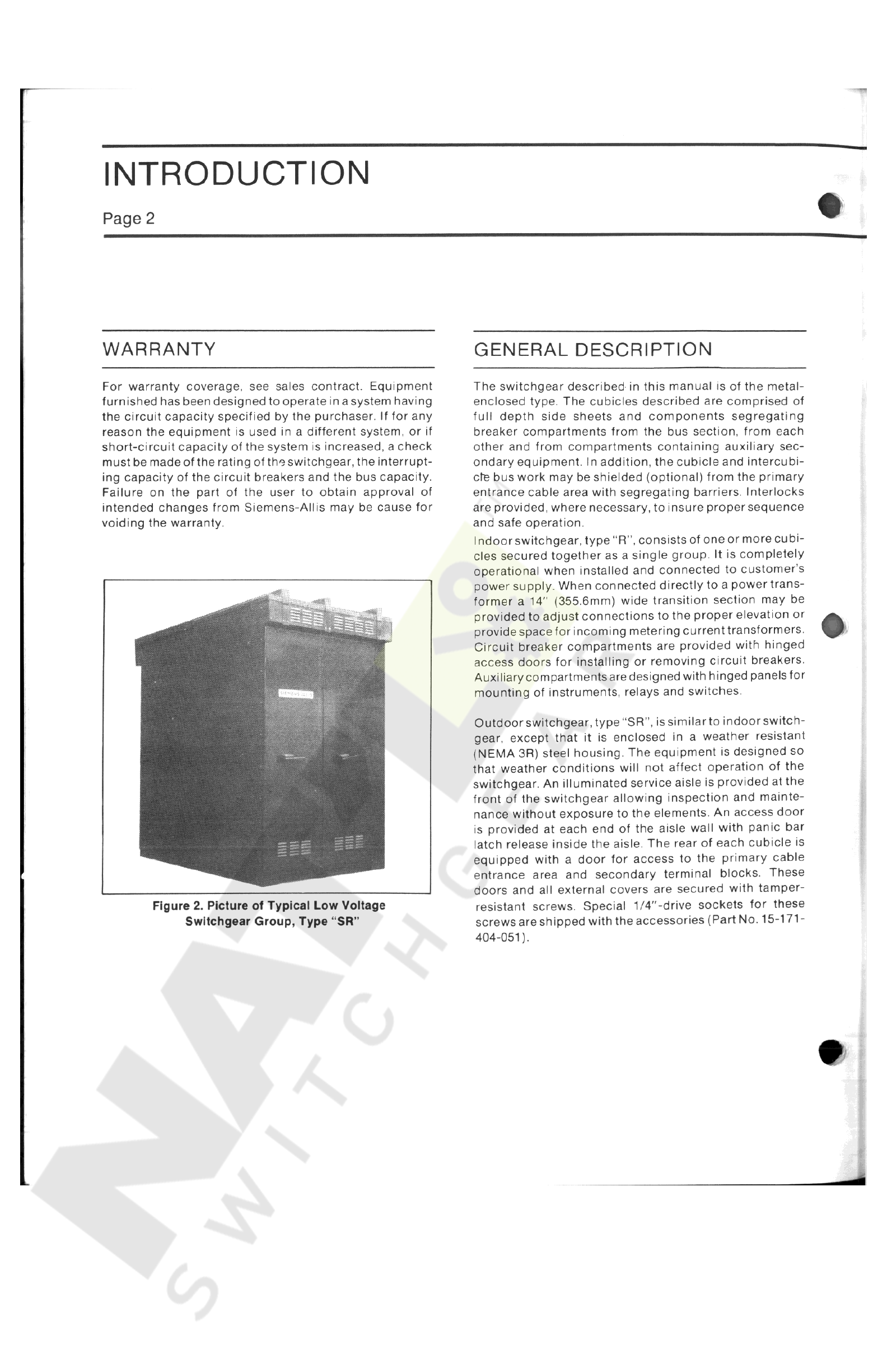
Figure
2
.
Picture
of
Typical
Low
Voltage
Switchgear
Group
,
Type
“
SR
”
Courtesy of NationalSwitchgear.com

I
4
I
FOUNDATION
Page
3
horizontal
plane
within
1
/
16
"
(
1.6
mm
)
.
There
should
not
beany
projection
above
this
plane
within
the
area
covered
by
the
switchgear
.
If
the
customer
’
s
floor
or
sills
do
not
meet
this
requirement
it
will
be
necessary
to
use
shims
when
installing
the
switchgear
on
the
mounting
surface
.
GENERAL
Prior
to
installation
of
the
switchgear
,
careful
design
,
planning
and
construction
of
the
foundation
or
base
on
which
the
switchgear
will
rest
must
be
made
.
A
thorough
analysis
and
careful
construction
may
alleviate
many
problems
at
the
time
of
installation
.
It
is
important
that
a
true
and
level
surface
be
provided
,
with
the
structure
being
capable
of
supporting
the
weight
of
the
switchgear
and
other
related
equipment
.
OUTDOOR
Concrete
slab
,
sill
channels
,
piers
or
pilings
,
whichever
type
of
foundation
is
used
,
must
have
smooth
and
level
surfaces
and
be
in
the
same
horizontal
plane
within
1
/
16
"
(
1
6
mm
)
.
If
these
conditions
are
not
met
it
will
be
neces
-
sary
to
shim
when
installing
the
switchgear
.
The
use
of
a
transit
to
obtain
a
true
level
during
foundation
construc
-
tion
is
recommended
.
In
any
group
of
outdoor
switchgear
support
points
shall
be
at
each
end
and
at
the
division
of
every
second
or
third
cubicle
,
however
,
the
span
between
supports
shall
not
exceed
66
"
(
1514
mm
)
,
see
Figure
4
.
If
pilings
are
used
,
the
diameter
is
to
be
determined
by
INDOOR
As
it
is
difficult
to
obtain
a
true
and
level
floor
on
a
con
-
crete
slab
,
it
is
highly
recommended
that
3
"
(
minimum
)
sill
channels
be
grouted
in
as
shown
in
Figure
3
.
It
should
be
noted
that
the
surface
of
the
sills
is
slightly
above
floor
level
.
The
surfaceof
the
sills
must
be
level
and
in
the
same
Anchor
Bolts
Front
3.0
"
(
76.2
mm
)
33.68
"
(
860.5
mm
)
«
*
i
1
J
y
A
Floor
Line
-
»
I
/
T
*
A
,
•
i
V
1
*
>
J
9
.
62
"
(
15.7
mm
)
Dia
.
Holes
for
Anchor
Bolts
or
Welding
to
Sills
I
*
1.0
"
Max
.
(
25.4
mm
)
Cust
.
Floor
Must
Not
Project
Above
Top
of
Sill
Channels
.
50
"
(
12.7
mm
)
Dia
.
Anchor
Bolts
or
Sill
Furn
.
By
Cust
.
When
Req
'
d
.
(
See
Alternates
)
Side
View
Indoor
Bolting
Arrg
’
t
.
Weld
to
Floor
Steel
Drill
and
Tap
Floor
Steel
Alternates
vMrmv
5
~
7
\
/
*
•
m
*
;
%
Figure
3
.
Indoor
Anchoring
Courtesy of NationalSwitchgear.com
t
-
FOUNDATION
Page
4
restrictions
,
conduit
couplings
may
be
grouted
in
flush
with
foundation
,
and
conduit
nipples
added
after
switch
-
gear
is
in
place
.
Conduits
should
be
capped
during
con
-
struction
to
prevent
entry
of
dirt
,
moisture
and
vermin
.
When
“
J
”
bolts
or
other
types
of
anchor
bolts
are
grouted
in
foundation
they
must
be
located
exactly
as
shown
on
general
arrangement
drawing
.
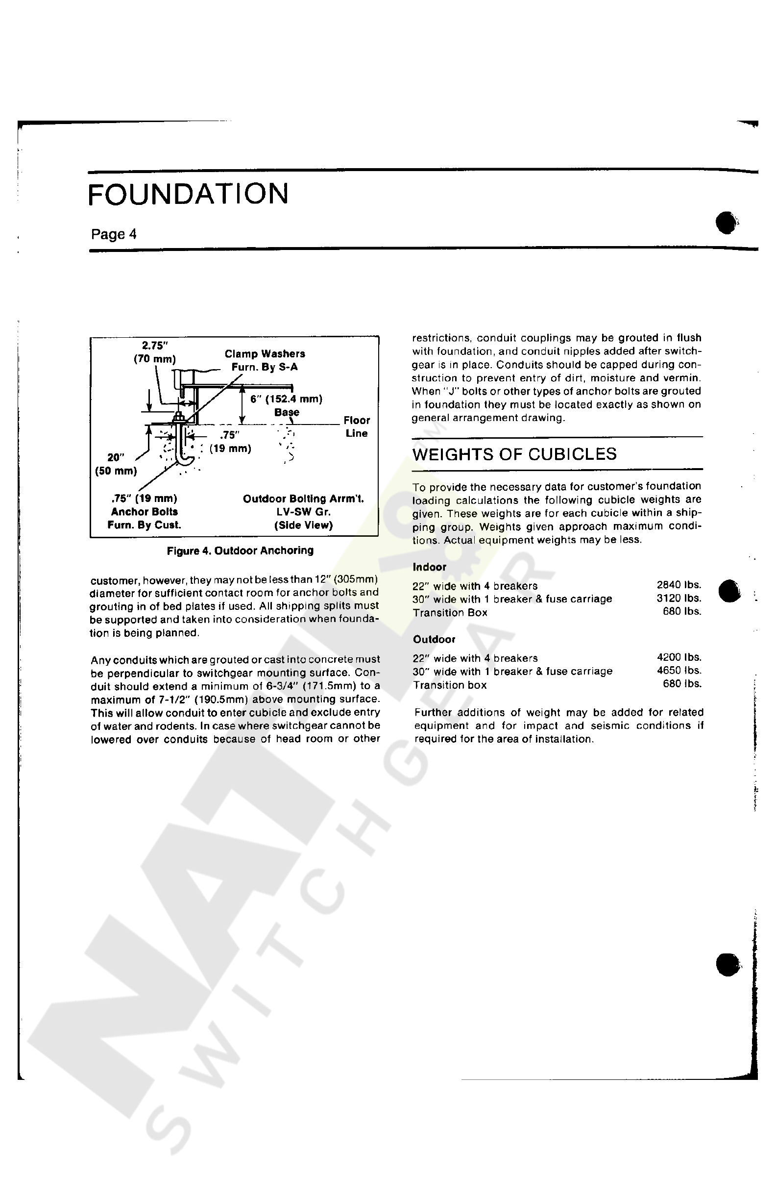
2.75
"
(
70
mm
)
Clamp
Washers
Furn
.
By
S
-
A
/
i
6
"
(
152.4
mm
)
Base
V
Floor
Line
\
|
4
—
•
:
(
19
mm
)
75
"
t
-
WEIGHTS
OF
CUBICLES
20
"
,
'
(
50
mm
)
To
provide
the
necessary
data
for
customer
’
s
foundation
loading
calculations
the
following
cubicle
weights
are
given
.
These
weights
are
for
each
cubicle
within
a
ship
-
ping
group
.
Weights
given
approach
maximum
condi
-
tions
.
Actual
equipment
weights
may
be
less
.
.
75
"
(
19
mm
)
Anchor
Bolts
Furn
.
By
Cust
.
Outdoor
Bolting
Arrm
’
t
.
LV
-
SW
Gr
.
(
Side
View
)
Figure
4
.
Outdoor
Anchoring
Indoor
22
"
wide
with
4
breakers
30
"
wide
with
1
breaker
&
fuse
carriage
Transition
Box
customer
,
however
,
they
may
not
be
less
than
12
"
(
305
mm
)
diameter
for
sufficient
contact
room
for
anchor
bolts
and
grouting
in
of
bed
plates
if
used
.
All
shipping
splits
must
be
supported
and
taken
into
consideration
when
founda
-
tion
is
being
planned
.
2840
lbs
.
3120
lbs
.
680
lbs
.
Outdoor
22
"
wide
with
4
breakers
30
”
wide
with
1
breaker
&
fuse
carriage
Transition
box
4200
I
bs
.
4650
lbs
.
680
lbs
.
Any
conduits
which
are
grouted
or
cast
into
concrete
must
be
perpendicular
to
switchgear
mounting
surface
.
Con
-
duit
should
extend
a
minimum
of
6
-
3
/
4
"
(
171.5
mm
)
to
a
maximum
of
7
-
1
/
2
"
(
190.5
mm
)
above
mounting
surface
.
This
will
allow
conduit
to
enter
cubicle
and
exclude
entry
of
water
and
rodents
.
In
case
where
switchgear
cannot
be
lowered
over
conduits
because
of
head
room
or
other
I
\
Further
additions
of
weight
may
be
added
for
related
equipment
and
for
impact
and
seismic
conditions
if
required
for
the
area
of
installation
.
fc
r
?
L
.
Courtesy of NationalSwitchgear.com
RECEIVING
AND
HANDLING
Page
5
drawings
.
These
numbers
insure
that
all
components
,
applying
to
a
particular
substation
,
are
correctly
located
before
uncrating
.
When
there
are
multiple
shipping
sec
-
tions
each
may
be
identified
by
an
attached
tag
giving
a
drawing
number
which
also
appears
on
the
customer
'
s
copy
of
the
shipping
list
.
The
shipping
list
also
describes
the
content
of
the
crate
or
package
as
cubicle
or
unit
No
.
1
-
2
-
3
etc
.
Refer
to
general
arrangement
drawing
for
loca
-
tion
of
each
shipping
section
within
a
group
line
-
up
.
GENERAL
Each
shipping
section
of
switchgear
is
securely
blocked
and
braced
for
shipment
.
It
is
crated
,
boxed
or
covered
as
required
by
shipping
conditions
.
Whatever
method
of
shipment
is
employed
,
every
precaution
is
taken
to
insure
its
safe
arrival
.
If
special
handling
is
required
,
it
is
so
indicated
on
the
shipment
.
All
moving
parts
are
secured
,
however
,
relatively
delicate
instruments
are
included
which
requires
that
each
section
be
handled
carefully
until
installed
in
its
final
location
.
INSPECTION
AND
UNCRATING
Before
uncrating
inspect
for
splintered
crate
or
other
abuse
.
In
the
process
of
uncrating
nail
pullers
are
recom
-
mended
.
The
use
of
sledge
hammers
and
crow
bars
could
bend
or
damage
the
finish
of
the
switchgear
.
Check
ship
-
ping
manifest
to
be
certain
that
all
items
have
been
received
.
Do
not
destroy
any
packing
material
until
all
items
listed
on
shipping
manifest
have
been
accounted
for
.
Small
packages
of
parts
can
be
lost
in
packing
mate
-
rial
.
Do
not
remove
identification
tags
from
apparatus
until
the
switchgear
is
completely
installed
.
If
there
are
any
shortages
,
or
damage
not
previously
noted
,
make
certain
it
is
noted
on
the
freight
bill
and
contact
carrier
and
Siemens
-
Allis
sales
office
immediately
.
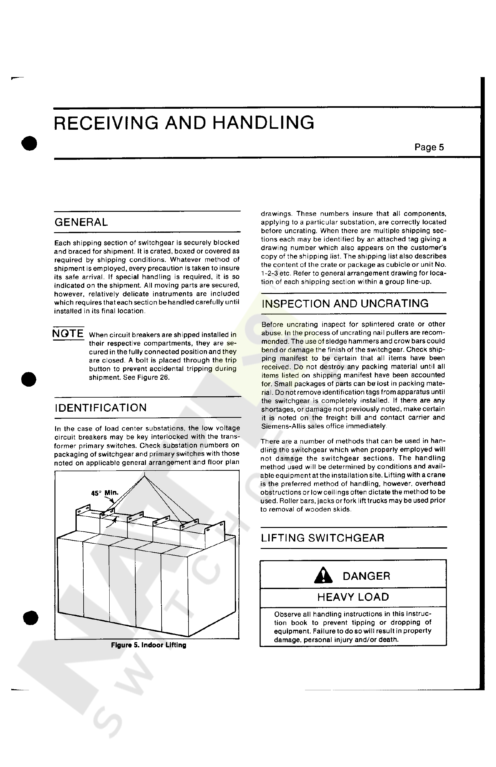
NOTE
When
circuit
breakers
are
shipped
installed
in
their
respective
compartments
,
they
are
se
-
cured
in
the
fully
connected
position
and
they
are
closed
.
A
bolt
is
placed
through
the
trip
button
to
prevent
accidental
tripping
during
shipment
.
See
Figure
26
.
IDENTIFICATION
In
the
case
of
load
center
substations
,
the
low
voltage
circuit
breakers
may
be
key
interlocked
with
the
trans
-
former
primary
switches
.
Check
substation
numbers
on
packaging
of
switchgear
and
primary
switches
with
those
noted
on
applicable
general
arrangement
and
floor
plan
There
are
a
number
of
methods
that
can
be
used
in
han
-
dling
the
switchgear
which
when
properly
employed
will
not
damage
the
switchgear
sections
.
The
handling
method
used
will
be
determined
by
conditions
and
avail
-
able
equipment
at
the
installation
site
.
Lifting
with
a
crane
is
the
preferred
method
of
handling
,
however
,
overhead
obstructions
or
low
ceilings
often
dictate
the
method
to
be
used
.
Roller
bars
,
jacks
or
fork
lift
trucks
may
be
used
prior
to
removal
of
wooden
skids
.
LIFTING
SWITCHGEAR
A
DANGER
HEAVY
LOAD
Observe
all
handling
instructions
in
this
instruc
-
tion
book
to
prevent
tipping
or
dropping
of
equipment
.
Failure
to
do
so
will
result
in
property
damage
,
personal
injury
and
/
or
death
.
Figure
5
.
Indoor
Lifting
Courtesy of NationalSwitchgear.com
RECEIVING
AND
HANDLING
Page
6
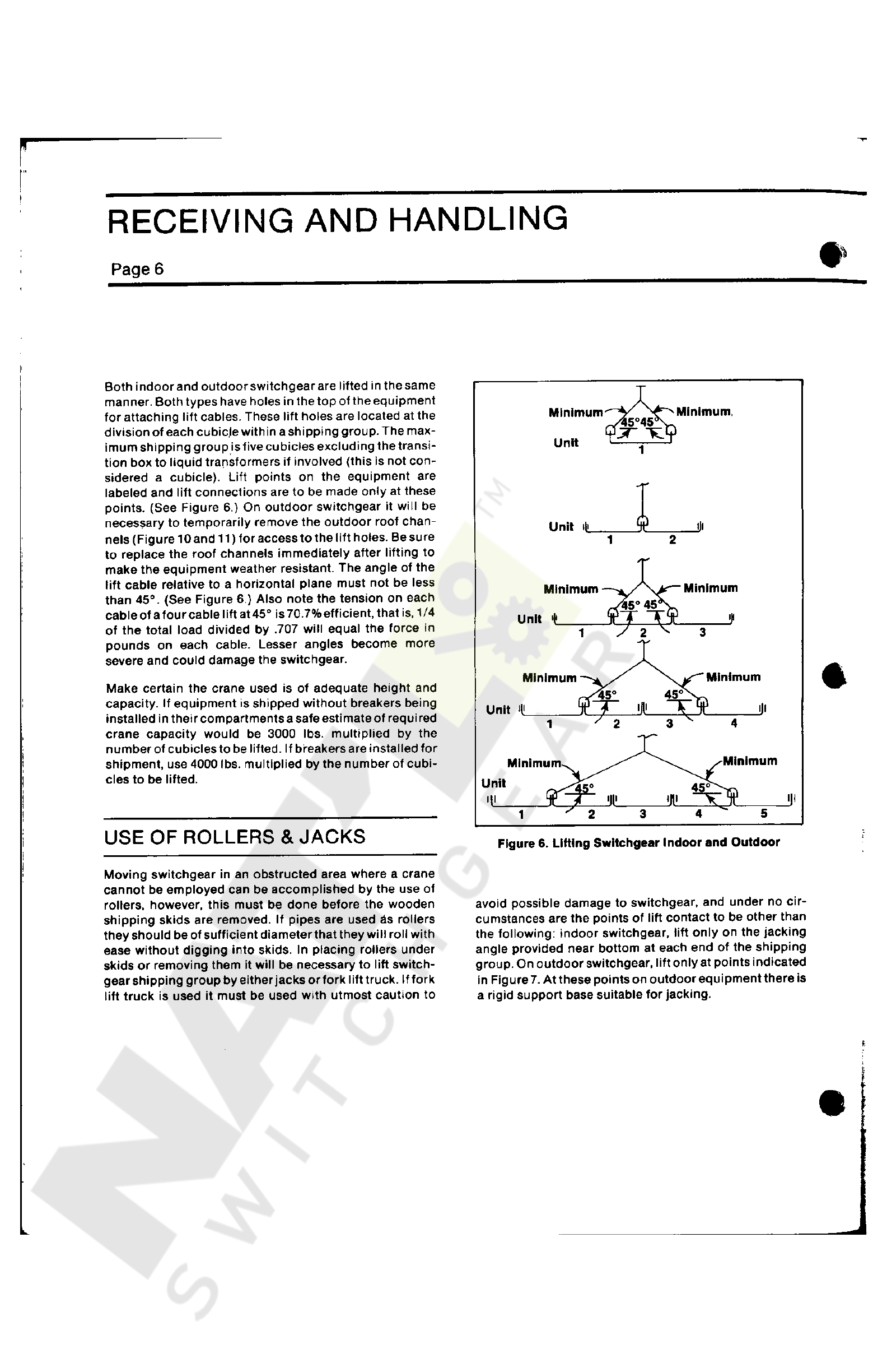
Both
indoorand
outdoorswitchgearare
lifted
in
the
same
manner
.
Both
types
have
holes
in
the
top
of
the
equipment
for
attaching
lift
cables
.
These
lift
holes
are
located
at
the
division
of
each
cubicle
within
a
shipping
group
.
The
max
-
imum
shipping
group
is
five
cubicles
excluding
the
transi
-
tion
box
to
liquid
transformers
if
involved
(
this
is
not
con
-
sidered
a
cubicle
)
.
Lift
points
on
the
equipment
are
labeled
and
lift
connections
are
to
be
made
only
at
these
points
.
(
See
Figure
6
.
)
On
outdoor
switchgear
it
will
be
necessary
to
temporarily
remove
the
outdoor
roof
chan
-
nels
(
Figure
10
and
11
)
for
access
to
the
lift
holes
.
Be
sure
to
replace
the
roof
channels
immediately
after
lifting
to
make
the
equipment
weather
resistant
.
The
angle
of
the
lift
cable
relative
to
a
horizontal
plane
must
not
be
less
than
45
°
.
(
See
Figure
6
.
)
Also
note
the
tension
on
each
cableof
afourcable
lift
at
45
°
is
70.7
%
efficient
,
that
is
,
1
/
4
of
the
total
load
divided
by
.
707
will
equal
the
force
in
pounds
on
each
cable
.
Lesser
angles
become
more
severe
and
could
damage
the
switchgear
.
Make
certain
the
crane
used
is
of
adequate
height
and
capacity
.
If
equipment
is
shipped
without
breakers
being
installed
in
their
compartments
a
safe
estimate
of
requi
red
crane
capacity
would
be
3000
lbs
.
multiplied
by
the
number
of
cubicles
to
be
lifted
.
If
breakers
are
installed
for
shipment
,
use
4000
lbs
.
multiplied
by
the
number
of
cubi
-
cles
to
be
lifted
.
USE
OF
ROLLERS
&
JACKS
Figure
6
.
Lifting
Switchgear
Indoor
and
Outdoor
Moving
switchgear
in
an
obstructed
area
where
a
crane
cannot
be
employed
can
be
accomplished
by
the
use
of
rollers
,
however
,
this
must
be
done
before
the
wooden
shipping
skids
are
removed
.
If
pipes
are
used
as
rollers
they
should
be
of
sufficient
diameter
that
they
will
roll
with
ease
without
digging
into
skids
.
In
placing
rollers
under
skids
or
removing
them
it
will
be
necessary
to
lift
switch
-
gear
shipping
group
by
either
jacks
or
fork
lift
truck
.
If
fork
lift
truck
is
used
it
must
be
used
with
utmost
caution
to
avoid
possible
damage
to
switchgear
,
and
under
no
cir
-
cumstances
are
the
points
of
lift
contact
to
be
other
than
the
following
:
indoor
switchgear
,
lift
only
on
the
jacking
angle
provided
near
bottom
at
each
end
of
the
shipping
group
.
On
outdoor
switchgear
,
lift
only
at
points
indicated
in
Figure
7
.
At
these
points
on
outdoor
equipment
there
is
a
rigid
support
base
suitable
for
jacking
.
f
Courtesy of NationalSwitchgear.com


TJ
1
»
<
l
#
1
STORAGE
Page
8
ble
oxidation
.
Do
not
lubricate
slide
rails
,
or
aluminum
hinge
gear
on
shutter
!
INDOOR
SWITCHGEAR
When
switchgear
is
not
to
be
erected
immediately
,
it
•
should
be
uncrated
and
inspected
for
damage
within
fif
-
teen
days
of
receipt
and
stored
in
a
clean
,
dry
location
.
Indoor
cubicles
are
neither
weather
resistant
nor
drip
re
-
sistant
;
therefore
,
they
should
be
stored
indoors
.
If
they
must
be
stored
outdoors
,
or
if
they
are
to
be
kept
in
a
humid
,
unheated
area
,
provide
adequate
covering
and
place
a
heat
source
of
approximately
500
watts
output
within
each
cubicle
to
prevent
condensation
.
Space
heat
-
ers
are
not
standard
equipment
on
indoor
switchgear
.
If
storage
is
for
an
extensive
period
of
time
lubricate
moving
parts
such
as
hinges
,
shutters
,
etc
.
to
protect
from
possi
-
OUTDOOR
SWITCHGEAR
When
storing
outdoor
switchgear
in
an
area
exposed
to
weather
or
humid
conditions
,
the
space
heaters
provided
must
be
energized
.
Access
to
heater
circuit
is
gained
through
rear
doors
.
See
wiring
diagram
for
terminal
identi
-
fication
.
If
storage
is
for
an
extensive
period
of
time
lubri
-
cate
moving
parts
such
as
hinges
,
shutters
(
but
not
the
shutter
hinge
gears
)
and
other
moving
parts
.
Do
not
lubri
-
cate
slide
rails
,
or
aluminum
hinge
gear
on
shutters
!
t
>
\
\
j
I
Courtesy of NationalSwitchgear.com

INSTALLATION
Page
9
installation
instruction
drawing
,
panel
arrangement
and
panel
arrangement
bill
of
material
,
nameplate
engraving
list
and
accessories
drawing
.
In
reading
this
instruction
book
special
attention
should
be
given
to
"
Foundation
”
already
covered
on
Pages
3
and
4
.
Check
the
foundation
whichatthistimeshould
be
complete
.
It
must
conform
to
the
requirements
described
in
this
book
and
the
general
arrangement
drawing
.
INTRODUCTION
Prior
to
installation
of
switchgear
read
this
instruction
book
and
drawings
mailed
at
an
earlier
date
,
such
as
general
arrangement
,
three
line
diagram
,
schematic
dia
-
gram
,
master
wiring
diagram
,
cubicle
wiring
diagram
,
S
«
e
Fig
.
6
for
Locating
Lifting
Cablet
Space
Available
In
Top
or
Bottom
of
Unit
*
For
Customers
Primary
and
Secondary
Cables
.
See
Instruction
Book
.
Customer
to
Oritt
Top
Plate
to
Suit
1.2
"
(
30.5
mm
)
Die
.
Lifting
Hole
*
TO
0
"
{
254
mm
)
25.94
(
651
9
mm
)
Ho
*
i
1
10.0
(
254
mm
|
Ref
.
>
96
2
"
(
2443
mm
)
Overall
—
W
y
vent
12.0
"
(
305
mm
)
Rear
Eat
i
26.0
’
MJ
;
'
(
370
mm
)
28.0
"
15.1
'
15.1
"
’
(
660.4
mm
)
e
”
(
355.6
mm
)
(
M
0.4
mm
)
14.0
"
(
363.5
mm
)
14
.
P
”
i
(
363.5
mm
)
,
.
14
,
y
,
12
'
(
30
5
mm
)
Rear
Door
:
1
14.0
'
53
(
355
6
mm
)
(
355
65
mm
)
(
355
-
6
mm
)
i
(
355.6
mm
)
J
-
Hinged
Rear
If
"
Dpor
(
Option
)
/
1 2
"
(
30.5
mm
)
Rear
Door
f
W A
»
*
1
60.0
'
(
1524
mm
)
Untl
Depth
Standard
23
5
'
30
-
0
'
(
762
mm
)
w
/
12
(
304.6
mm
)
Exttn
.
26
.
Q
'
(
660.4
mm
)
w
/
8
"
(
203
2
mm
)
Eaten
.
14
0
'
(
457
2
mm
)
w
/
0
Eaten
.
Rear
/
*
\
(
597
mm
)
Hot
si
Eaten
Exien
.
(
Opilon
)
r
T T
\
.
16.0
'
(
457
mm
)
I
J
102.0
'
(
2561
mm
)
Top
of
Holst
r
,
•
0
0
"
(
1524
mm
)
Standard
Unit
Depth
TK
I
o
S
*
c
Wir
.
O
Sac
-
oo
o
With
Breaker
in
Bo
Horn
Position
Cable
Space
Is
Obstructed
Here
Wir
.
Throat
I
I
i
Loc
.
Loc
.
I
i
7
J
.
2
"
(
IBS
9
mm
)
c
c
£
33.66
'
(
660.5
mm
)
3
=
J
D
i
4.8
~
42
"
(
1067
mm
)
V
MJn
—
ft
.
Space
Recommended
With
30
"
(
762
mm
)
Artie
Recom
—
»
Side
6
Rear
O
'
OJ
(
122
mm
)
12
"
34.64
(
865
mm
)
40.9
f
(
1039
mm
)
b
-
J
40.9
"
13.94
'
13
94
"
13.94
"
13.94
'
Rear
nr
(
1038.6
mm
)
"
*
j
Extension
<
354
mm
)
I
(
»
4
mm
)
(
354
mm
)
(
354
mm
)
f
I
i
I
t
Floor
t
J
.
I
'
“
4
J
I
I
Une
Front
Location
oi
Holes
In
Bottom
of
Units
for
Anchor
Bolls
—
See
Sotting
Arrangement
9.94
'
{
252.5
mm
)
9.94
"
(
252.5
mm
)
3
0
'
U
Customer
Conduit
1.5
'
1
Maximum
Above
Floor
J
1
A
(
76.2
mm
)
33
88
'
3.0
"
Hinged
Panels
(
880.5
mm
)
(
76.2
mm
)
(
139.7
mm
)
Side
View
w
/
Hotil
4
Anchor
Bolting
Floor
Plan
Figure
9
.
Typical
Indoor
Floor
Plan
and
Side
View
Courtesy of NationalSwitchgear.com

INSTALLATION
Page
10
INSTALLING
SHIPPING
SECTIONS
As
previously
covered
under
“
Foundation
,
”
mounting
sur
-
faces
,
sills
,
slab
,
piers
or
pilings
must
be
level
and
in
the
same
plane
.
Also
,
conduits
must
be
properly
located
and
perpendicular
to
such
a
degree
that
they
will
clear
the
floor
plate
cutouts
.
Mounting
surfaces
must
be
swept
free
of
stones
,
chips
and
other
debris
which
might
impede
rollers
or
leveling
of
switchgear
.
The
proper
method
of
installation
depends
on
whetherthe
switchgear
has
been
shipped
as
one
complete
group
,
or
in
two
or
more
shipping
sections
.
The
general
arrangement
drawing
will
indicate
the
shipping
sections
,
cubicle
num
-
bers
and
their
location
within
the
switchgear
line
-
up
.
Sec
-
tions
are
assembled
and
wired
in
accordance
with
the
arrangement
as
in
final
installation
.
!
11
?
.
315
"
(
2851
mm
)
Overall
See
Figure
6
for
Locating
Lifting
Cablet
$
0
*
e
»
Available
In
Toe
04
Bottom
ol
Unit
*
lor
Cuitom
*
Primary
and
1
aeon
dory
Cable
-
$
o
*
Instruction
Book
.
Cutlomor
lo
Drill
floor
Plate
or
Hoof
lo
lull
Shippin
?
Group
$
0.12
'
'
—
(
1427
mm
)
26.0
'
Shippfng
Group
sur
(
1324
am
)
-
220
"
11
-
0
"
(
558.8
mm
)
1
23
Diam
*
l
»
f
Lifting
Holes
in
floof
ol
Flange
Each
Unit
Accessible
With
Channel
Removed
Removable
Roof
Channel
v
I
11.12
“
(
282
mm
)
u
.
ir
(
3
$
4
mm
’
|
m m
)
11.0
'
6.0
'
9
(
203
mm
)
Aisle
Eilenelon
,
9.44
-
•
Cable
Spec
*
Top
(
240
mm
)
10.00
V
-
Cable
Spec
*
Bottom
(
2
S
4
nun
)
13.44
”
(
341
mm
)
14.00
"
9.44
"
_
1194
“
(
3032.8
mm
)
Overall
V
50
'
(
1270
mm
)
(
240
mm
)
10.0
P
"
(
254
mm
)
4
I
22
'
Holst
X
{
558.8
mm
)
2.0
"
*
—
>
(
Ui
mm
)
+
L
I
(
T
V
»
nt
^
f
T
Liquid
Filled
Transformer
Throat
J
Vant
Vent
14.8
"
(
1378
mm
)
31
(
78.2
mm
)
‘
Overhang
t A
L
A
N
j
/
\
L
JAL
j
/
f
\
/
'
'
7
r
*
.
7
t
Secondary
Wiring
Location
I s
3.0
'
A
14.0
{
76
2
mm
)
£
*
cc
*
a
V
0
E
N
C
as
(
355.8
mm
)
\
30.0
"
(
762
mm
)
Aisle
Recomm
,
Side
$
Rear
113.38
"
(
2880
mm
)
Unit
Depth
\
\
/
3
tf
J
T
42.06
'
(
1008
mm
)
Able
'
A
59.84
"
(
1522
mm
)
Inner
Unit
t
3.0
-
7
2.0
-
?
2
\
118.4
-
9.0
/
(
228.6
mm
)
110
-
0
"
(
2784
mm
)
(
78.2
mm
)
1.5
"
(
38
mm
)
(
50.8
mm
|
-
re
(
3033
mm
)
3.0
”
\
I
7
i
Over
(
78.2
mm
)
ee
st
st
Hoof
c
Captive
Temper
-
reslelenl
Hardware
on
Doors
I
A
With
Breaker
In
Bottom
Position
Cable
Space
Is
Obstructed
Mere
Front
Inner
Unit
See
Anchor
Bolling
Detail
Papa
4
c
c
c
D
=
3
3
Hang
Door
Handle
Ol
Oi
Ol
"
i
-
78.78
-
{
1850
mm
)
*
{
122
mm
)
i
i
.
25
-
Front
3.0
”
A
3
33
88
'
(
860.5
mm
)
i
l
(
6
35
mm
)
(
76
J
2
mm
)
Hinged
Inner
Panels
*
Floor
I
J
-
Line
.
75
'
.
75
"
78.81
“
(
2027
mm
)
1
(
19
mm
)
*
{
19
«
m
)
Suggested
Location
tor
Customer
*
Anchor
Boris
.
See
Bolting
Arrangement
and
Mote
.
II
Required
,
Additional
Boris
Other
Than
Location
Shown
Must
Be
Located
on
Unit
1.31
'
Base
11.0
'
*
r
w
Front
(
13.3
mm
)
i
(
279.4
mm
)
t
^
^
\
(
1024
mm
)
le
—
(
102
mm
)
V
Hinged
Door
Each
Unh
8.0
"
<
152.4
mm
)
Besa
f
Side
Section
With
Outdoor
Anchor
Bolting
J
A
J
"
s
"
I
4
“
Customer
ConduM
7
5
“
Maximum
Above
Floor
Line
(
102
mm
)
(
102
mm
)
Figure
10
.
Typical
Outdoor
Floor
Plan
h
*
Courtesy of NationalSwitchgear.com

!
INSTALLATION
Page
11
is
in
firm
contact
with
the
mounting
surface
.
In
the
absence
of
contact
,
shims
must
be
added
adjacent
to
the
anchor
bolt
holes
.
These
shims
will
prevent
distortion
of
the
section
when
anchor
bolts
are
drawn
tight
.
Shims
should
be
approximately
three
inches
square
with
a
thickness
determined
by
the
existing
requirement
or
attained
by
stacking
.
Tighten
anchoring
hardware
,
and
check
for
level
.
If
line
-
up
consists
of
more
than
one
ship
-
ping
section
,
the
next
section
should
be
moved
into
place
being
certain
that
front
panels
are
in
line
with
those
of
the
first
section
.
Repeat
the
same
plumbing
as
done
on
the
first
section
;
insert
hardware
for
bolting
the
two
sections
together
,
but
do
not
tighten
.
Repeat
the
leveling
,
shim
-
ming
and
tightening
of
anchoring
hardware
as
on
the
first
section
.
Tighten
hardware
holding
the
two
shipping
sec
-
tions
together
.
Repeat
this
procedure
for
each
shipping
section
in
the
line
-
up
.
SETTING
SHIPPING
SECTIONS
After
checking
each
shipping
section
for
its
proper
loca
-
tion
sequence
,
as
shown
on
the
general
arrangement
drawing
,
move
the
first
section
of
the
switchgear
to
its
location
.
When
a
transformer
is
part
of
the
installation
and
in
its
correct
location
,
the
switchgear
is
positioned
next
to
the
transformer
as
shown
in
Figure
16
.
The
shipping
sec
-
tion
should
be
kept
high
enough
to
just
clear
any
conduits
and
then
moved
toward
the
transformer
to
the
dimensions
shown
on
the
general
arrangement
drawing
.
At
the
same
time
align
switchgear
with
the
anchor
bolt
locations
and
conduit
locations
below
.
With
all
points
aligned
and
with
conduit
caps
and
floor
plate
covers
removed
,
carefully
lower
the
section
to
its
permanent
location
.
It
is
important
that
the
first
section
be
accurately
positioned
and
leveled
as
each
successive
section
will
depend
on
the
first
.
PLUMBING
AND
LEVELING
INSTRUCTIONS
LEVELING
OUTDOOR
SWITCHGEAR
As
described
under
“
Foundation
,
"
Pages
3
and
4
of
this
instruction
book
,
the
floor
,
sills
,
piers
,
or
pilings
are
to
be
true
and
in
a
level
plane
,
and
within
the
area
of
the
switch
-
gear
in
the
case
of
a
slab
or
floor
there
are
no
projections
such
as
pebbles
in
the
concrete
protruding
above
this
plane
.
This
being
accomplished
there
should
not
be
any
problem
in
plumbing
or
leveling
the
switchgear
.
Plumbing
and
leveling
outdoor
equipment
is
basically
the
same
as
indoor
.
When
resting
on
its
permanent
founda
-
tion
cubicles
should
be
plumb
within
1
/
8
"
(
3.2
mm
)
.
Unlike
indoor
the
equipment
is
anchored
through
the
use
of
studs
or
“
J
”
-
bolts
grouted
into
foundation
and
with
clamp
washers
gripping
the
switchgear
base
.
Examine
area
adjacent
to
each
anchor
stud
to
make
certain
that
the
base
is
in
firm
contact
with
the
mounting
surface
.
If
there
are
areas
adjacent
to
these
studs
which
are
not
in
contact
with
the
mounting
surface
of
the
slab
,
piers
or
pilings
they
must
be
brought
into
contact
by
use
of
shims
.
These
shims
will
prevent
distortion
of
the
base
when
anchor
hardware
is
drawn
tight
.
With
all
points
of
contact
checked
and
ship
-
ping
section
properly
located
tighten
anchor
hardware
.
If
there
are
additional
shipping
sections
each
one
in
se
-
quence
should
be
aligned
with
that
previously
anchored
.
Check
foundation
contact
,
plumb
and
add
shims
as
required
in
same
manner
as
first
group
installed
.
Draw
the
anchor
hardware
tight
,
install
and
tighten
the
hardware
bolting
the
sections
together
and
proceed
to
the
next
section
,
if
any
.
If
the
general
arrangement
drawing
has
been
followed
there
should
not
be
any
shipping
split
(
between
twoshipping
sections
)
which
is
unsupported
by
pier
or
pilings
.
Install
roof
channels
,
one
for
each
shipping
split
,
as
shown
in
Figure
11
.
PLUMBING
To
make
certain
that
there
has
been
no
distortion
of
switchgear
in
shipping
or
handling
each
shipping
section
should
be
checked
with
a
plumb
Iine
after
it
is
resting
on
its
permanent
level
foundation
.
A
plumb
line
dropped
from
the
top
front
corner
at
each
end
of
the
shipping
section
should
verify
that
the
section
is
vertical
within
1
/
8
"
(
3.2
mm
)
.
Out
of
plumb
greater
than
1
/
8
"
(
3.2
mm
)
usually
indicates
an
uneven
base
and
shimming
may
be
required
.
LEVELING
INDOOR
SWITCHGEAR
Examine
each
cubicle
through
its
4
anchor
bolt
holes
,
those
shown
on
the
general
arrangement
drawing
,
to
make
certain
that
in
the
area
of
the
anchor
bolt
the
cubicle
Courtesy of NationalSwitchgear.com
INSTALLATION
Page
12
Stop
Angle
1
Stop
Angle
Track
©
©
.
'
Jt
?
L
CT
'
1
Figure
11
.
Outdoor
Roof
Channels
R
.
H
.
End
Unit
L
.
H
.
End
Unit
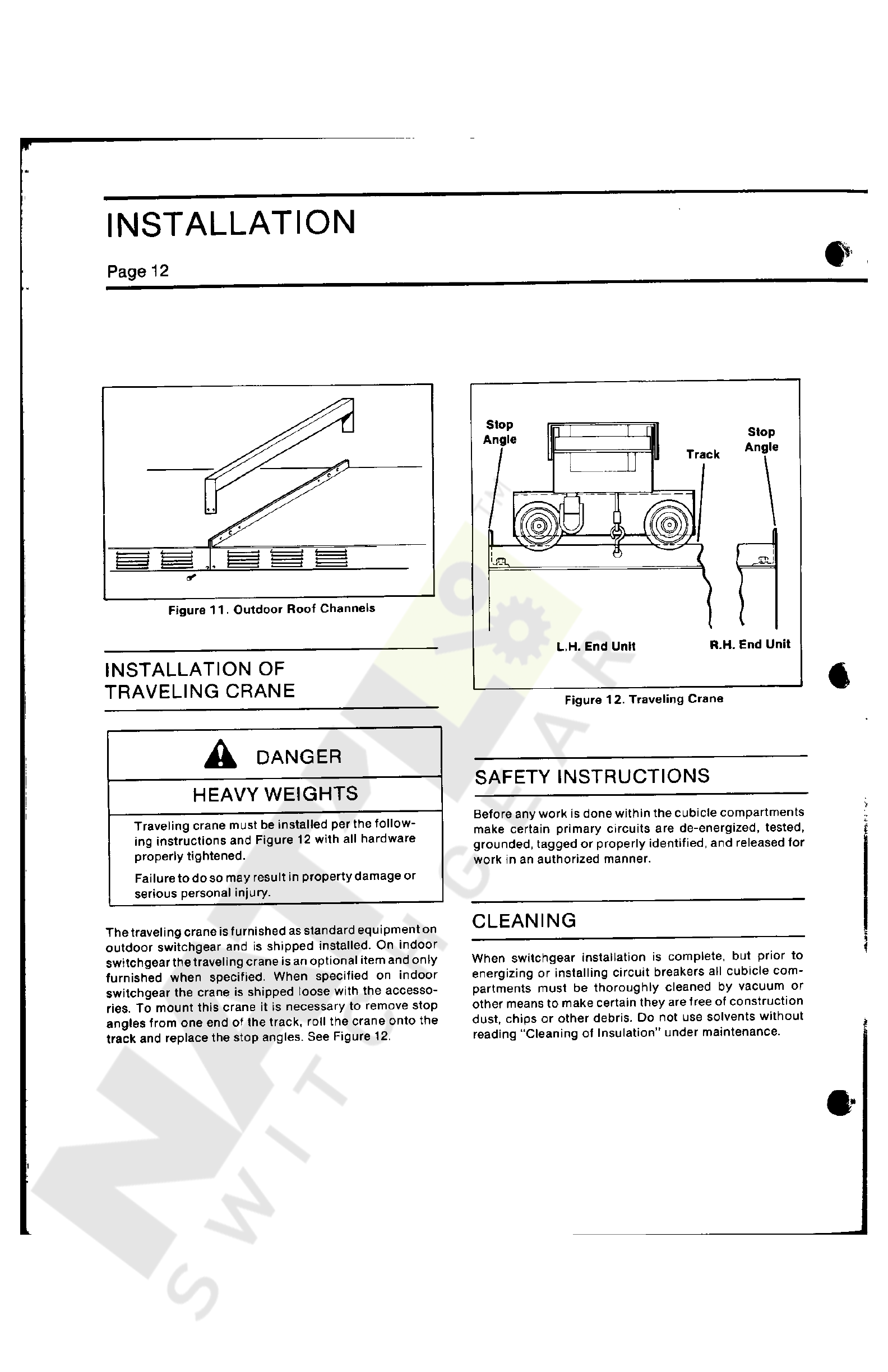
INSTALLATION
OF
TRAVELING
CRANE
%
Figure
12
.
Traveling
Crane
DANGER
SAFETY
INSTRUCTIONS
HEAVYWEIGHTS
>
Before
any
work
is
done
within
the
cubicle
compartments
make
certain
primary
circuits
are
de
-
energized
,
tested
,
grounded
,
tagged
or
properly
identified
,
and
released
for
work
in
an
authorized
manner
.
Traveling
crane
must
be
installed
per
the
follow
-
ing
instructions
and
Figure
12
with
all
hardware
properly
tightened
.
Failure
to
do
so
may
result
in
property
damage
or
serious
personal
injury
.
Jf
CLEANING
The
traveling
crane
is
furnished
as
standard
equipment
on
outdoor
switchgear
and
is
shipped
installed
.
On
indoor
switchgearthe
traveling
crane
is
an
optional
item
and
only
furnished
when
specified
.
When
specified
on
indoor
switchgear
the
crane
is
shipped
loose
with
the
accesso
-
ries
.
To
mount
this
crane
it
is
necessary
to
remove
stop
angles
from
one
end
of
the
track
,
roll
the
crane
onto
the
track
and
replace
the
stop
angles
.
See
Figure
12
.
1
When
switchgear
installation
is
complete
,
but
prior
to
energizing
or
installing
circuit
breakers
all
cubicle
com
-
partments
must
be
thoroughly
cleaned
by
vacuum
or
other
means
to
make
certain
they
are
free
of
construction
dust
,
chips
or
other
debris
.
Do
not
use
solvents
without
reading
“
Cleaning
of
Insulation
"
under
maintenance
.
t
Courtesy of NationalSwitchgear.com

ELECTRICAL
CONNECTIONS
Page
13
1
.
All
surfaces
must
be
free
of
dust
,
dirt
,
and
other
for
-
eign
material
.
2
.
Do
not
use
any
abrasive
cleaner
on
plated
contact
surfaces
.
Cleaning
normally
is
not
necessary
and
should
not
be
done
unless
parts
are
badly
tarnished
.
If
cleaning
is
necessary
,
use
a
mild
cleaner
and
thor
-
oughly
rinse
parts
to
remove
all
residue
.
3
.
Assemble
all
joints
with
parts
dry
.
Do
not
use
any
grease
or
oxide
preventing
compounds
even
where
aluminum
buses
are
used
.
Aluminum
buses
and
con
-
nectors
requiring
bolted
connections
are
tin
plated
and
can
be
applied
directly
to
other
tin
plated
alumi
-
num
parts
or
silver
plated
copper
bars
without
the
use
of
an
oxide
preventing
compound
.
4
.
For
method
of
bolting
joints
,
see
Figure
14
,
and
follow
hardware
tightening
instructions
.
PRIMARY
CONNECTIONS
BUS
BARS
AND
CONNECTORS
Bus
bars
,
risers
and
various
connectors
may
be
of
alumi
-
num
or
copper
as
required
by
the
specification
of
each
order
(
Fig
.
13
)
.
When
the
specification
calls
for
aluminum
all
bus
and
connector
joints
with
exception
of
shipping
splits
,
neutral
bus
,
primary
contacts
and
termination
points
joining
other
equipment
are
of
welded
construc
-
tion
.
Each
weldment
has
been
carefully
designed
to
meet
the
temperature
rise
limitations
as
set
forth
by
ANSI
Standards
,
C
37.20
.
At
shipping
splits
and
termination
points
the
tin
plated
aluminum
bars
have
holes
for
1
/
2
"
hardware
for
coupling
of
splice
plates
or
connectors
to
other
equipment
.
When
the
specifications
require
a
copper
bus
system
all
joints
are
of
bolted
construction
,
and
com
-
pletely
assembled
at
factory
except
for
shipping
split
spli
-
ces
and
termination
points
to
other
equipment
.
Contact
areas
are
silver
plated
and
may
be
coupled
to
tin
plated
aluminum
bars
or
to
other
silver
plated
copper
bars
.
HARDWARE
NOTE
All
bus
joint
hardware
furnished
is
zinc
plated
,
dichromate
treated
high
strength
steel
.
Cap
screws
are
1
/
2
-
13
SAE
Grade
5
,
nuts
are
SAE
Grade
2
,
hexagon
,
heavy
.
Sizes
and
grades
other
than
above
are
not
to
be
used
.
Tighten
1
/
2
-
13
hardware
to
within
a
torque
range
of
50
-
75
ft
.
lbs
.
(
67.8
to
101.7
N
m
)
.
Should
specifications
call
for
special
hard
-
ware
as
silicon
bronze
or
stainless
steel
consult
factory
for
BOLTED
BUS
JOINTS
When
bus
joints
are
field
assembled
the
following
proce
-
dure
shall
be
followed
for
both
copper
and
aluminum
conductors
:
Figure
13
.
Bus
and
Risers
Courtesy of NationalSwitchgear.com

f
ELECTRICAL
CONNECTIONS
Page
14
proper
torque
range
.
For
copper
arrange
hardware
as
shown
in
Figure
15
with
flat
washer
on
each
side
of
joint
and
lockwasher
between
the
flat
washer
and
the
nut
.
When
aluminum
bus
or
a
mixture
of
aluminum
and
copper
bars
is
involved
the
lockwasher
and
flat
washer
under
the
nut
are
replaced
by
a
single
"
Belleville
”
spring
washer
.
The
concave
side
of
this
spring
washer
is
placed
against
the
bus
or
splice
plate
.
Torque
requirements
are
the
same
as
described
above
.
Do
not
exceed
the
torque
range
given
.
Forces
within
this
range
will
produce
a
low
resis
-
tance
joint
without
cold
flow
of
material
(
Fig
.
15
)
.
Shipping
Split
FRONT
OF
UNIT
Spiice
Bar
Plan
View
A
jflk
Bus
Bar
TOT
2
"
Bolt
Cft
Gnd
.
Bus
Bar
Gnd
.
Splice
Splice
Bar
NOTE
All
hardware
furnished
is
plated
,
high
strength
steel
.
Capscrews
are
1
/
2
-
13
SAE
Grade
5
.
’
Hex
nuts
are
SAE
Grade
2
.
*
Do
not
use
metric
hardware
Bus
Bar
3
w
Bus
Bar
i
3
”
Bolt
CQi
(
Cb
Gnd
.
Bus
Bar
Gnd
.
Splice
Cap
Screw
Flat
Washers
f
Splice
Bar
Bus
Bars
Bus
Bar
Lock
Washer
Silver
Plated
Copper
I
j
^
Gnd
.
Splice
TOJ
4
"
Bolt
Flat
Washer
n
Gnd
.
Bus
Bar
Cap
Screw
Tin
Plated
Aluminum
{
Belleville
Washer
Nut
Bus
Bar
Flat
Washer
Silver
Plated
Copper
Neutral
Bus
Cap
Screw
ns
m
Splice
Bar
Gnd
.
Splice
a
jfl
7
f
I
Tin
Plated
Aluminum
Gnd
.
Bus
Bar
Belleville
Washer
Nut
Bus
Bar
&
Figure
15
.
Bus
Joint
Hardware
\
)
Neutral
Bus
<
-
i
CONNECTION
TO
POWER
TRANSFORMER
i
Splice
Bar
Gnd
.
Splice
Gnd
.
Bus
Bar
Before
making
the
primary
connections
to
a
liquid
trans
-
former
it
will
be
necessary
to
remove
the
transition
box
cover
for
access
.
The
joints
connecting
power
trans
-
formers
to
the
switchgear
are
the
same
as
joints
previously
i
i
Shipping
Split
Figure
14
.
Bolted
Bus
Joints
Courtesy of NationalSwitchgear.com
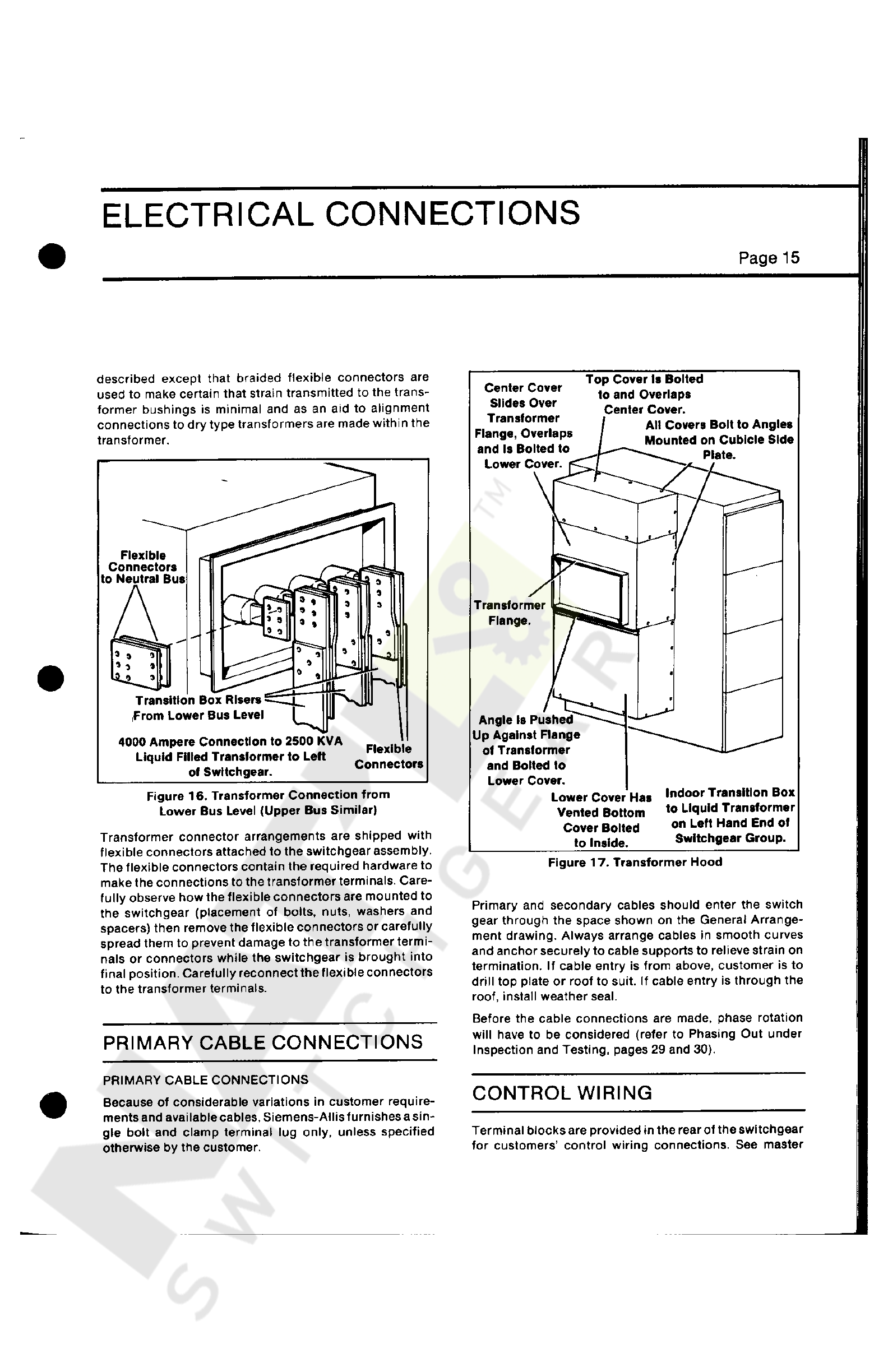
ELECTRICAL
CONNECTIONS
Page
15
described
except
that
braided
flexible
connectors
are
used
to
make
certain
that
strain
transmitted
to
the
trans
-
former
bushings
is
minimal
and
as
an
aid
to
alignment
connections
to
dry
type
transformers
are
made
within
the
transformer
.
Top
Cover
Is
Bolted
to
and
Overlaps
Center
Cover
.
Center
Cover
Slides
Over
Transformer
Flange
,
Overlaps
and
Is
Bolted
to
Lower
Cover
,
r
All
Covers
Bolt
to
Angles
Mounted
on
Cubicle
Side
-
—
_
Plate
.
V
?
Flexible
Connectors
to
Neutral
Bus
$
*
*
*
|
9
Transformer
Flange
.
3
Vo
»
*
0
r
'
P
o
•
o
0
1
*
*
9
®
0
*
3
$
*
*
00
a
*
0
0
Transition
Box
Risers
rFrom
Lower
Bus
Level
Angle
Is
Pushed
Up
Against
Flange
of
Transformer
and
Bolted
lo
Lower
Cover
.
4000
Ampere
Connection
to
2500
KVA
Liquid
Filled
Transformer
to
Lett
of
Switchgear
.
Flexible
Connectors
Indoor
Transition
Box
to
Liquid
Transformer
on
Left
Hand
End
of
Switchgear
Group
.
Figure
16
.
Transformer
Connection
from
Lower
Bus
Level
(
Upper
Bus
Similar
)
Transformer
connector
arrangements
are
shipped
with
flexible
connectors
attached
to
the
switchgear
assembly
.
The
flexible
connectors
contain
the
required
hardware
to
make
the
connections
to
the
transformer
terminals
.
Care
-
fully
observe
how
the
flexible
connectors
are
mounted
to
the
switchgear
(
placement
of
bolts
,
nuts
,
washers
and
spacers
)
then
remove
the
flexible
connectors
or
carefully
spread
them
to
prevent
damage
to
the
transformer
termi
-
nals
or
connectors
while
the
switchgear
is
brought
into
final
position
.
Carefully
reconnect
the
flexible
connectors
to
the
transformer
terminals
.
Lower
Cover
Has
Vented
Bottom
Cover
Bolted
to
Inside
.
Figure
17
.
Transformer
Hood
Primary
and
secondary
cables
should
enter
the
switch
gear
through
the
space
shown
on
the
General
Arrange
-
ment
drawing
.
Always
arrange
cables
in
smooth
curves
and
anchor
securely
to
cable
supports
to
relieve
strain
on
termination
.
If
cable
entry
is
from
above
,
customer
is
to
drill
top
plate
or
roof
to
suit
.
If
cable
entry
is
through
the
roof
,
install
weather
seal
.
Before
the
cable
connections
are
made
,
phase
rotation
will
have
to
be
considered
(
refer
to
Phasing
Out
under
Inspection
and
Testing
,
pages
29
and
30
)
.
PRIMARY
CABLE
CONNECTIONS
PRIMARY
CABLE
CONNECTIONS
Because
of
considerable
variations
in
customer
require
-
ments
and
available
cables
,
Siemens
-
Allis
furnishes
a
sin
-
gle
bolt
and
clamp
terminal
lug
only
,
unless
specified
otherwise
by
the
customer
.
CONTROL
WIRING
Terminal
blocks
are
provided
in
the
rear
of
the
switchgear
for
customers
’
control
wiring
connections
.
See
master
Courtesy of NationalSwitchgear.com

ELECTRICAL
CONNECTIONS
Page
16
FEEDER
BRKR
LUG
ARR
Up
or
Down
Feed
Optional
7
.
A
/
—
Approx
.
21.50
"
to
Rear
of
Unit
<
6
BNW
200
n
\
Gnd
.
Lug
Extension
c
8
BNW
150
(
1
)
4
SW
625
(
1
)
47.5
to
Bottom
Floor
Plate
JTFb
In
Unit
Grd
.
Bar
a
3
s
\
OD
o
o
GRD
LUG
MTG
.
6
BNW
200
NEUTRAL
LUG
ARR
SO
q
Up
to
(
4
)
Lugs
per
Unit
00
-
851
-
497
-
012
As
Req
’
d
J
Eft
m
ES
Gnd
.
Lug
Extension
/
EI
0
Inner
Unit
Neutral
Bar
Neutral
Lug
Extension
GRD
LUG
MTG
.
6
BNW
-
200
Minimum
Bare
Clearance
Phase
to
Phase
,
Phase
to
Grd
.
FEEDER
BRKR
LUG
ARR
.
6
BNW
-
200
(
2
)
(
4
)
1.0
L J
i
Neutral
Bar
Neutral
Lug
Extension
NEUTRAL
LUG
ARR
w
/
C
.
T
.
’
s
6
BNW
200
(
D
8
BNW
-
200
tnftrrf
(
4
)
o
zJ
6
BNW
200
(
2
)
I
Lug
6
BNW
150
\
\
<
2
)
\
Adaptor
oN
)
A
Similar
Adaptor
Arrangement
Can
Be
Used
for
Compartment
#
1
or
#
3
to
Clear
Neutral
Lug
Extension
FEEDER
BRKR
LUG
ARR
.
FEEDER
BRKR
.
COMPARTMENT
#
4
(
DN
FEED
)
Figure
18
.
Lug
Arrangement
wiring
diagram
for
wire
designations
.
Intersectional
wir
-
ing
at
shipping
splits
is
connected
and
tagged
as
shown
on
master
wiring
diagram
for
customers
'
ease
in
field
connection
.
On
ventilated
dry
transformer
installations
,
a
conduit
is
furnished
for
wiring
between
switchgear
and
the
temperature
cpntrol
system
box
on
the
transformer
.
This
conduit
is
installed
and
wired
by
the
customer
in
the
field
.
On
liquid
filled
transformer
installations
,
the
conduit
is
furnished
with
the
transformer
for
connecting
to
the
switchgear
in
the
field
.
All
secondary
wiring
installed
by
factory
is
bundled
and
cleated
to
the
side
plate
.
Make
all
field
connections
in
a
similar
manner
as
shown
in
Figure
19
.
Courtesy of NationalSwitchgear.com

ELECTRICAL
CONNECTIONS
Page
17
)
Current
transformers
for
metering
are
generally
mounted
on
the
stationary
primary
disconnect
studs
and
are
readily
accessible
for
inspection
and
replacement
.
Current
transformers
for
static
trip
device
use
are
called
“
tripping
transformers
”
.
They
have
a
one
ampere
second
-
ary
and
are
not
suitable
for
metering
.
They
are
mounted
on
the
circuit
breaker
except
when
a
ground
fault
trip
element
is
furnished
for
a
four
-
wire
application
.
In
this
case
,
a
fourth
tripping
transformer
is
mounted
in
the
cable
compartment
on
the
neutral
bus
or
in
the
link
between
the
neutral
bus
and
the
ground
bus
.
This
will
be
shown
on
the
three
-
line
diagram
and
may
require
that
the
neutral
cables
be
connected
to
it
with
the
cable
lugs
furnished
.
GROUND
CONNECTIONS
A
common
ground
bus
is
incorporated
in
all
cubicles
for
properly
grounding
the
switchgear
after
installation
.
Each
cubicle
has
a
tap
from
the
ground
bus
to
the
primary
entrance
cable
compartment
.
Provisions
for
connecting
this
ground
bus
to
the
station
ground
must
be
made
by
customer
in
a
reliable
manner
.
Figure
19
.
Control
Wiring
CURRENT
TRANSFORMERS
WARNING
^
HAZARDOUS
VOLTAGE
Do
not
operate
any
current
transformer
with
secondaries
open
circuited
.
To
do
so
may
cause
property
damage
,
burns
or
possible
death
.
Figure
20
.
Ground
Connection
Courtesy of NationalSwitchgear.com
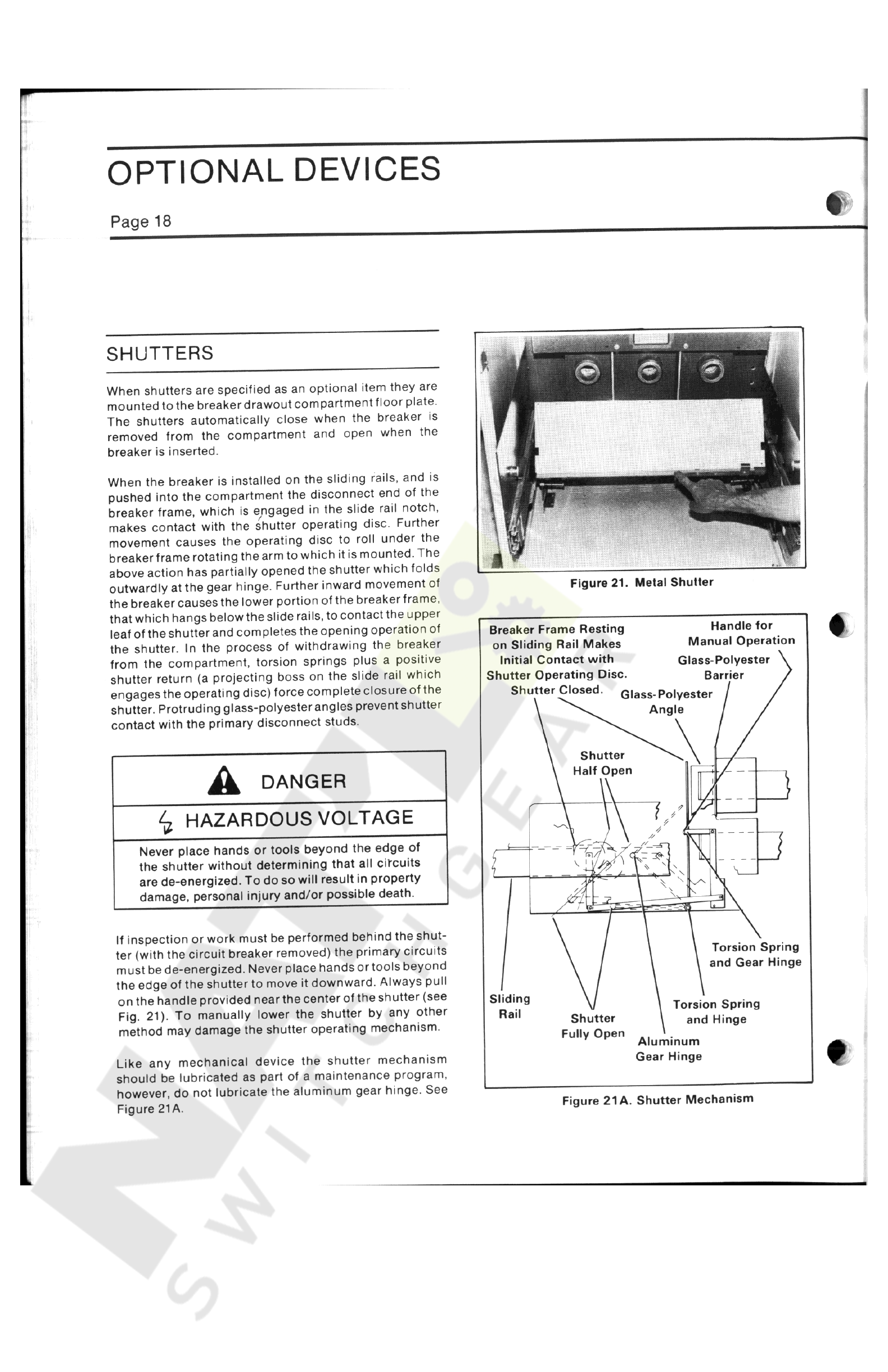
OPTIONAL
DEVICES
Page
18
SHUTTERS
When
shutters
are
specified
as
an
optional
item
they
are
mounted
to
the
breaker
drawout
compartment
floor
plate
.
The
shutters
automatically
close
when
the
breaker
is
removed
from
the
compartment
and
open
when
the
breaker
is
inserted
.
When
the
breaker
is
installed
on
the
sliding
rails
,
and
is
pushed
into
the
compartment
the
disconnect
end
of
the
breaker
frame
,
which
is
engaged
in
the
slide
rail
notch
,
makes
contact
with
the
shutter
operating
disc
.
Further
movement
causes
the
operating
disc
to
roll
under
the
breaker
frame
rotating
the
arm
to
which
it
is
mounted
.
The
above
action
has
partially
opened
the
shutter
which
folds
outwardly
at
the
gear
hinge
.
Further
inward
movement
of
the
breaker
causes
the
lower
portion
of
the
breakerframe
,
that
which
hangs
below
the
slide
rails
,
to
contact
the
upper
leaf
of
the
shutter
and
completes
the
opening
operation
of
the
shutter
.
In
the
process
of
withdrawing
the
breaker
from
the
compartment
,
torsion
springs
plus
a
positive
shutter
return
(
a
projecting
boss
on
the
slide
rail
which
engages
the
operating
disc
)
force
complete
closure
of
the
shutter
.
Protruding
glass
-
polyesterangles
prevent
shutter
contact
with
the
primary
disconnect
studs
.
Figure
21
.
Metal
Shutter
Handle
for
Manual
Operation
Glass
-
Polyester
\
Barrier
/
Breaker
Frame
Resting
on
Sliding
Rail
Makes
Initial
Contact
with
Shutter
Operating
Disc
.
Shutter
Closed
.
Glass
-
Polyester
Angle
Shutter
Half
Open
A
DANGER
)
1
/
^
HAZARDOUS
VOLTAGE
'
,
.
-
3
l
-
J
Never
place
hands
or
tools
beyond
the
edge
of
the
shutter
without
determining
that
all
circuits
are
de
-
energized
.
To
do
so
will
result
in
property
damage
,
personal
injury
and
/
or
possible
death
.
r
*
}
A
v
'
*
\
*
—
\
\
,
1
If
inspection
or
work
must
be
performed
behind
the
shut
-
ter
(
with
the
circuit
breaker
removed
)
the
primary
circuits
must
be
de
-
energized
.
Never
place
hands
ortools
beyond
the
edge
of
the
shutter
to
move
it
downward
.
Always
pull
on
the
handle
provided
nearthecenter
of
the
shutter
(
see
Fig
.
21
)
.
To
manually
lower
the
shutter
by
any
other
method
may
damage
the
shutter
operating
mechanism
.
Torsion
Spring
and
Gear
Hinge
Sliding
Torsion
Spring
and
Hinge
Rail
Shutter
Fully
Open
Aluminum
Gear
Hinge
Like
any
mechanical
device
the
shutter
mechanism
should
be
lubricated
as
part
of
a
maintenance
program
,
however
,
do
not
lubricate
the
aluminum
gear
hinge
.
See
Figure
21
A
.
Figure
21
A
.
Shutter
Mechanism
Courtesy of NationalSwitchgear.com
This manual suits for next models
2
Other Siemens-Allis Circuit Breaker manuals


