Siemens-Allis LA-3200A User manual

WAHRANTY
I
NS
T
AL
LATION
ANO
I
NSPECT
IO
N
ln
tr
oduc;t1o n .
R
ecc
1vino tHHi
ln
sp1
?c
taon
fq
t Dn
n,
nqe
l
ns
ta
ll
<J
lion
.
Sw
r:.i
g
•~
.
Ma
i
11t
en.ince .
OPERAT
ION
D
es
cri
pti
on
Ma
nua
llv ·
Op
er3
rerl
Br
e
ak
er
El
ect
r
ic
ally-Opera
ted
Br
ea
ke
r .
Drawout
I
nt
er
l
ock
.
Racking
Mecha
n
ism.
Lift
i
ng
Bar
&
Ra
il
Ext
e
nsions
.
Sp
r
ing
Disc
harge
Int
er
lock
.
M
AINTENANCE
AND
ADJ
U
STMENTS
Mai
n
te
nan
ce . .
Lub
ri
cation
.
Maintenance
Cl
osing
Handli
ng
Instruc
ti
on
Fig.
1
Fig.
2
Fig.
3
Fig.
4
T
yp
ical L
A-3000A
Breaker
Outli
ne.
Typ
ical
LA·30
00A
-
4000A
Opera
t
or
Typi
cal
Wiri
ng
Diag
r
am
- El
ectr
i
cally
Operated
Br
eakers
....
Typical
Rack
ing
Mec
h
anism
and
Drawout
I
nterlock
Fig. 5
Main
t
enance
Closing
Table
1
Oper
ating
Procedure
- Ma
nu
ally
·
Operated
Breakers
. .
..
...
.
Table
2
Operat
i
ng
P
rocedure
-
Electrical
Iy ·
Operated
Breakers
.
"
. 2 ·
L2
3
3
4
4
4
8
5
6
6.
21
6
.17
13
14
15
16
18
3
4
A<l1t
1S
t
!T
Wr\
t$
Tr
1p -
L11
t
ch
Enci;
t
CJl~f
nt-!
n
t
Mn
1n
Co
11t
:1cr
Mnke
.
Arc
1
r1q
Con
1;
1c1
Mnk
".
Contac:t R
t!
p lttCf!rTit!
nt
.
M.1
in C
on
t;
1cr
F1
nuers .
Srn
11
on
:
11
v A 1c1ng
Con
ta
ct
H 1
nge
Con
tact
F
1ng
ers .
Mo
v
11H
JArr.1n
<J
and
Mai
n Co
nt
a
ct
Tr
1pp1nq A
ctuntor.
Motor
Cu
roff
Sw
it
ch
Sec
onda
ry D isc.
Opt
ion .
Aux
i
liary
Sw
i
tc
h
Option
.
Shunt
Tr
ip
Op
t
ion
TRIP
PING
TRANSFORMERS
Curr
ent
Se
nso
rs
Trippi
ng
Transformer
Tab
le
Bell
A larm
Sw
i
tc
h
Option
St
at
ic
Tr
ip
Opt
io
n .
Lim
iT ri
p.
Undervo
ltage
Trip
Dev
ice
Opt
i
on.
L
ubr
ica
ti
ng
In
structions
I
nstruct
ion
Boo
k
Ref
.
Fig. 6 T y pical P
anel
Assembly
F
ig
. 7
Secondary
Disconnect
Fig. 8
Auxil
i
ary
Sw
i
tc
h
Fi
g.
9
Shunt
Tr
ip
.
Fi
g. 10
Unde
r
voltage
Tr
ip.
Fig
. 11
Bell
Alarm.
Tab
le 3
Ma
i
ntena
nce
Cl
osing
Table
4
Tr
ip
Rat
in
g
Ta
b le -
Amperes
Static
Tr
ip
II
.
T
ab
le 5
Tr
ip R
at
i
ng
Table
Li
mi
Tr
ip
.
. .
7
7
7
8
8
8
8
8
8
8
9.
10
. 11
. 1 1
.11
. 11
11
. 12
. 11
. 12
12
11
21
22
19
19
19
19
.
20
.
20
i
12
i 2
T
he
i
nfo
r
mation
contained
w i
thi
n is in
tende
c
~
o
assist
opera
tin g
pe
rsonne
l
by
p
rovid
i
ng
in
formation
on
th
e
genera
l
ch
arac
te
ri
stics
o f
equ
i
pment
o f th
is
type.
I t
does
not
reliev e
th
e user
of
r
espo
nsi
bi
li
ty
t0
use
sound
engineeri
ng
practice
-s in
the
i
nsta
ll
ation,
application
,
operation
and
main
tenance
of
t
he
part
icu
lar
equ
i
oment
pu
rchased
.
If
draw
i
ng
s
or
o t
her
supplemen
t
ary
i
nst
ru
ctio
ns
for
specific
app
l
ications
are
forwarded
w
it
h
th
is
rnanua
l
or
separately,
they
ta
ke
p
recede
nc
e
over
any
co
n
flicti
n g
or
i
ncom
p
lete
info
r
mat
i
on
in
this
manua
l.
Courtesy of NationalSwitchgear.com

WARRAN
TY
. ·Sicm<'ns-Allis
"LA"
air
circuit
lm
•akPrs ar
l'
warrant1·d
lo
lw
fn
•c ,
>f
(kft'<'Ls
in
mat.
nial
and
workma
nship
for
a pe
ri
od
of
one
year
from
datl'
of
in
iti
al
<>pnation
hut
not
mon
•
than
1·ighl1'c1
1
11\(>rlLhs
from
date·
of
s
hipml'nl
hy
company
.
This
warranty
is l
imited
to
Lhl'
furnish
ing
of
any
part. w
hi
ch
to
our
s;\l
i
~l'<ldinn
has h!'('ll pro»·
c·n
dPfPcti\'l'. Si('tnl'ns-J\llis
will
not
in
any casl' assunw
r<'
spons
ibil
ity
for
alliPd 1·quiprn
l'nt
1if
any
kind.
(S<'E'
S
i1
:nH'ns-
Alli
s
Warranty
Form
20160).
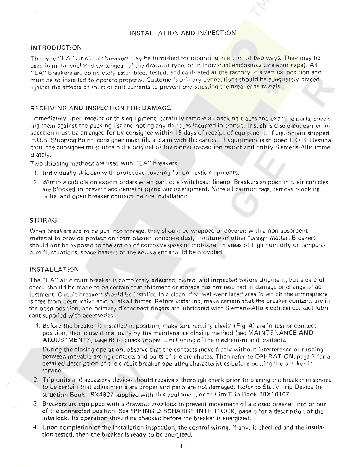
Typic
al
Shipping
Methods
Used
With
"LA"
Breakers
II
Courtesy of NationalSwitchgear.com
INSTALLATION
AND
INSPECT
IO
N
INTRODUCTION
The
type
"LA"
air
circu
it breakers may be fu
rn
ished
for
mou
nt
ing in
either
of
two
ways.
They
may
be
use
d in metal·enclosed switchgear
of
the
drawout
type,
or
in
individual
enclosures
(drawo
ut
type).
All
"LA"
breakers are
co
mpl
ete
ly
asse
mbled, tested, and
ca
libr
ated
at
the
factory
in a vertical
position
and
must be
so
installed
to
operate proper
ly.
Customer's
prim
ary connections
sh
oul
d be adeq
uately
braced
aga
inst the effects
of
sh
ort
circ
uit
currents
to
prevent overstressing the breaker terminals.
RECEIV
IN
G
AND
INSPE
CTION
FOR
DAMAGE
Immedia
tely
upon
receipt
of
this
equipm
ent,
caref
ully
remove all packing traces and examine parts, check-
ing
th
em
against the packing list
an
d
noting
any damages i
nc
urr
ed in transit.
If
such
is
disclosed, carrier in-
spection
must
be arranged
for
by
consignee
within
15 days
of
receipt
of
equipment
.
If
equipment
sh
ipped
F
.0
.B.
Shipping
Point,
consignee
must
fi
le a
claim
with
the carrier.
If
equipment
is
sh
ipped F.O.
B.
Destina-
tion,
the
con
signee
mu
st
obt
ain
th
e original
of
th
e carrier inspection
report
and
notify
Siemens-
Allis
imm
e-
diately.
Two
ship
pin
g
methods
are
us
ed
with
"LA"
breakers:
1.
Individually
skidded
with
pro
t
ec
tive covering
for
domestic shipments.
2.
Within
a cubicle
on
exp
ort
orders
when
part
of
a swi
tchg
ear lineup. Breakers shipp
ed
in
their
cubicl
es
are bl
ock
ed
to
prevent acciden
ta
l
tripping
duri
ng shi
pm
ent.
Note
all
caution
tags,
remove
blocking
bolts, and open breaker
con
tacts b
efor
e insta
llati
on.
STORAG
E
Wh
en
breakers
ar
e
to
be
put
into
stora
ge,
they
should be wrapped or covered
with
a
non
-absorbent
material
to
provide
protection
from
pl
aster, concrete dust, moisture
or
other
foreign matter_ Breakers
sh
ould n
ot
be exposed
to
the
acti
on
of
cor
rosive
gase
s
or
moisture. In a
r.eas
of
hi
gh
humidity
or
tempera-
ture
fluctuations,
sp
ace
heate
rs
or
the equivale
nt
should be provided_
I
NSTAL
LA
TI
ON
The"
LA"
air
cir
c
uit
breaker
is
com
ple
tely
adjusted, tested, and inspected
befo
re shipment,
but
a care
ful
ch
ec
k
sh
ould
be made
to
be
cert
ain
th
at
shipment or storage has
not
resu
lted
in damage
or
change
of
ad
-
justm
e
nt
.
Circuit
breakers should be install
ed
in a clean,
dry,
well-ven
ti
lated ar
ea
in
which
the
atmo
sp
here
is
free
from
destructive acid
or
alkali fumes. Before insta
lling
, make certain
tha
t the breaker
contacts
are in
th
e open pos
itio
n, and
primary
discon
nect
fin
gers are l
ubr
icated
with
Siemens-Allis ele
ct
rical
contact
lubr
i-
cant
supplied
with
accessories.
1. Befo
re
the
breaker is install
ed
in
position,
make sure racking clevis' (Fig.
4)
are in test
or
con
nect
posi
tion,
then
cl
ose
it
manually
by
the
maintenance closing me
thod
(see
MAINTENANC
E
AND
ADJUSTMENTS
, page 6)
to
check
proper
functioning
of
the mechanism and contacts.
During
the
clos
ing
operation,
observe
that
the
c
ontact
s move freely
without
interference
or
rubbing
between movable arcing contacts and parts
of
the arc chutes. Then r
efer
to
OP
E
RATION,
page 3
for
a
detailed
description
of
the
circ
uit
breaker operating chara
ct
eristics
befo
re
putting
the breaker in
service.
2_
Trip
units
and accessory devices
sh
ould
receive a
thorough
check
prior
to
placing the b
re
aker in service
to
be certain
that
adjustments are
proper
and
pa
rts are
not
dama
ged
. Refer
to
Stat
ic
Trip
Devi
ce
In
-
struction
Book
18X
4
827
supplied
with
this
equipment
or
to
LimiTrip
Book
18X
10107_
3. Breakers are equ
ipp
ed
with
a
drawou
t int
er
lock
to
prevent
movement
of
a clos
ed
breaker
into
or
out
of
the
connected
position.
See
SPRING
DISCHARGE
INTERLOCK,
page 5
for
a description
of
the
interlock
. I
ts
operation
should
be
checked before the breaker
is
energized.
4.
Upon
complet
ion
of
the installation inspection,
the
c
on
trol
wiring,
if
any,
is
check
ed
and
the
insula-
t
~
on
t
es
ted,
then
the
breaker
is
ready
to
be energiz
ed
.
- 1 -
Courtesy of NationalSwitchgear.com

CAUTIONS
TO
BE
OBSERVED
IN
THE
'
STA
LLATIO
N
AND
OPERATION
OF
"LA"
CIRCUIT
BREAKERS
1.
Never
try
to
remo
ve
the
breaker
from
the
compartment
or
reinsert
into
the
compartment
without
using the guide rail extensions supplied.
See
page 17.
2. Read the
Instruction
Book
before
installing
or
making
any
changes
or
adjustments on the breaker.
3. As the closing springs
on
stored-energy breakers
may
be charged
with
the breaker
contacts
in
either
the
open
or
closed
position,
extreme
care should be taken
to
discharge the springs before
working
on
the
breaker.
4.
When charging manually-operated breakers, always
hold
handle
firm
ly
unt
il
it
is
returned
to
the
nor
mal
vertical
position
.
5. Check
current
ratings against single line diagram
to
assure
that
breakers are
properly
located in switch·
gear at instal
lation.
6. Check the
alignment
of
the
secondary disconnect fingers
to
ensure against
misalignment
due
to
possible
distor
t
ion
of
fingers
during
shipment
and handling.
7. Once the breaker
is
energized,
it
should
not
be touched,
except
for
operating, since
most
of
the com-
ponent
parts are also energized.
MAINTENANCE
Occasional chec
king
and cleaning
of
the
breaker
will
promote
long and
trouble
-free service. A
periodic
in-
spection and servicing on an annual basis should be
included
in the breaker maintenance
routine
or
at
c:horter intervals
if
necessary
due
to
environmental
or
operating conditions.
the
circuit
breaker
is
not
operated
auring
extended periods,
the
breaker should
not
remain in
either
the
closed
or
open
position
any
longer than six
months.
Maintenance opening and closing operations sho
uld
be
made
to
ensure freedom
of
mo
vement
of
all parts.
. 2 -
Courtesy of NationalSwitchgear.com
..
OPERATION
DESCRIPTION
The
LA
-
3200
air
circuit
breaker
has
a
maximum
continuous
current
rating
of
3,200
ampere
s,
and
an
interruption
rating
of
65,000
amperes
at
254,
508,
or
635
volts
60
Hz., when used
with
the
short
time
delay trip device.
With
instantaneo
us
trip
device, the
interruption
rating
is
85,000
ampe
res
at
254
vol
ts,
65,000 ampe
res
at
508
volts,
an
d 65,000 amperes
at
635
volts.
The
LA-4000A
and B
air
circu
it
breakers have a
continuous
cur
rent
rating
of
4,000
ampe
res
and
an
int
er-
ruption
rating
of
85,0
00
amperes when used
with
the
short
time
delay
trip
device. The inter
ruption
rating
with
instantaneous
trip
device is 130,000 amperes at
254
volt
s,
85,000
amperes
at
508
volt
s, and
85,000
amperes
at
635
vo
!ts. All
currents
are
symmetrical amperes and
vol
tages are
maximum.
Th
ree
configur
at
ions
of
the
operator
are availab
le
for
charging the closing springs. These are:
(
A.
) manual charging,
(B.)
electrical charg
ing
(C.)
combina
t
ion
manual-electrical charging
All operato
rs
are
identical
except
for
the means
of
supp
lying
energy
to
the closing springs.
A
double-to
ggle,
tr
ip-free mechanism is
use
d;
that
is,
the
breaker contacts are free
to
open
at
any
time,
if
required, regardless
of
the
position
of
the
mechanism.
(A.)
Manually-Operated Breaker (Refer
to
F
ig
ure 2 a
nd
Table
1)
The breaker has a
center
-
mounted
frame so
many
of
the
latches and
li
nks
are arranged in pairs;
for
descrip-
tive purposes
they
wil
l be referred
to
as
single items. Detail
"A"
s
how
s
the
position
of
the
trip
latch and
toggle linkage
when
the breaker
is
open and
the
closing springs are discharged.
Movement
of
the
charging
handle
downw
ard rotates closing cam (
204
) against
roller
(168),
thus
pivoting
closing cam (
159
)
about
pin
(215) and
extending
t
he
closing springs
thru
l
ink
(163) and spring hanger (157).
Rotation
of
cam (159)
allows
ro
ller (181) in
to
gg
le linkage
to
be moved in
to
position
shown in Det
ai
l
"B".
Kickoff
springs (199)
move rolle
rs
away
from
stop
bloc
k
(1
71
),
then the toggle linkage
is
moved
by
torsion
spring
unti
l latch
(175) clear
trip
la
tch
(153A).
Spring (155) causes
trip
latch
(15
3A
)
to
reset
under
lat
ch (175).
Trip
flap
(1538)
should
normally
stop against the
front
surface
of
latch (175).
When the closing springs are
fully
charged,
ro
ll
er
(
168
) engages latch (
148).
Charging cam (
204
)
engages
pawl (146) in such a
manner
that
the charging cam
must
complete
the
charging stroke
before
it
can return
to
its
normal
position.
With
the
charging handle in
its
normal
upright
posi
tion,
the
breaker can
be
closed. By pressing
firmly
on
hood
(149), latch
(148)
will di
sengage
roller
(168) and closing springs
cau
se
closing cam (159)
to
rot
ate
aga
inst
the
toggle rollers (181 )
movi
ng
the
togg
le
into
its
upright
pos
it
ion, shown in detail
"C"
. T
he
closing
cycle can be in
terrupt
ed
at
any
po
int
by
operation
of
one
of
the
tripping
means,
which
cause
rotat
ion
of
trip
latch (
153A
)
to
a
position
that
rele
ases
latch (175)
allowing
toggle linkage
to
collapse
to
the
position
shown in detail
"A".
Manual opening
of
the
breaker
is
accomplished
by
pressing in manual
trip
bar
(
188
).
This
bar
engages
the
top
of
trip
flap
(1
538
)
which
is in tu
rn
arranged
to
disengage the
tr
ip latch
(175).
TABLE
1 -
OPERAT
I
NG
PROCEDUR
E -
MANUALLY
-
OPERATED
BREAKERS
Operation
Charging Springs
Closing
Tripping
Procedure
Make
su
re
that
th
e racking clevis' are in
either
test
or
connect
po
sition.
Never pull
charging handle
down
with
clevis' in disconnect
position
as
shown in Fig. 4.
Pull charging handle
down
all
the
way
(approximately
120
°) and
return
to
normal
vertical
position.
(Engagement
of
paw
l
with
the ratchet teeth prevents handle
re·
versal
until
the
downward
stroke is completed.)
Push
down
firmly
on
spring-release
latch
hood
(149)
after
handle
is
returned
to
normal
vertical
position.
Push
in
manual
tr
ip
bar
(
188
),
OR
If
shunt
trip
is
provided, operate r
emo
te
trip
control
switch
(CST).
(See
Figure 3.)
- 3 -
Courtesy of NationalSwitchgear.com
(B.)
Electrically
-
Op
erated Breaker (Refer
to
Figure 1
-2
and
4)
:
The
mechanism
of
the
electrically
operated breaker
is
th
e same
as
the manually
oper
ated breaker
except
th
at
the
manual cha
rg
i
ng
handle
is
replaced
by
a
motor
and gear system.
With
power
ava
ilable
to
the con-
trol
ci
rcuit,
closing the
motor
con
trol
switch
(Ml)
wil
l
sta
rt
the
automat
ic charging cycle.
The
motor
gear
box
pinion
rotate
s gear (
224
) co
unterclockwis
e, cam
follower
(233)
engages
an
arm
of
wind
and close
ca
m (
223
) which rotates
the
cams in the
sam
e manner
as
for
the manually charged breaker. When the
wind
and close earn (223) reaches its charged pos
ition
, the back
of
t
he
cam
eng
ages
switch lever
(229)
rotating
t
he
lever away
from
the
switch
operator.
Gea
r switch lever
(23
1) will still
be
holding
th
e
switch
in the operate posi
tion,
and
the
motor
will
continue
to
run
until
the
roll
pin
s on the side
of
gear (
224)
lifts
lever (231) clear,
re
leasing
the
motor
cutoff
switch
{M
CO
).
When the MCO switch op
en
s,
th
e
motor
sto
ps,
and the closi
ng
coil
circuit
is
set
up
through
one side
of
the
MCO swi
tc
h.
The
bre
aker can
now
be closed
by
depressing the latch
hood
(
149
)
or
by
energizing the closing
co
il
(CC)
throu
gh
the external close
control
switch
(CSC). When
the
close
circuit
is
energized, the
"Y
" relay
is
energi
ze
d and opens
the
"Y"
contact
in
the
mo
tor
circuit,
thus p
re
venting
"pu
mp
i
ng"
or
repeated at-
tempts
to
charge the
clo
sing springs.
If the close
circuit
CSC
switch
is
open
ed
,
the
motor
will
au
tom
atically
recharge the closing springs,
if
power
is
ava
ilable
for
the
motor
circuit.
The
cl
ose
coil circu
it
is
always
interr
upted
by
the
motor
cut-o
ff
s
witch
MC
O.
Trip
free
operation
of
the
mechanism, discharging
the
sprinQs on a closed breaker
is
pre-
vented
by
comp
leting
the
close
coil
circuit
through
an
auxiliary
contact
of
the breaker.
TABLE
2 -
OPERAT
I
NG
PROCEDURE
- E
LECT
RICA
LLY
-
OPERATED
BR
EAK
ERS
CAUTION!!
MAK
E
SURE
THAT
RACKING
CLEVIS
' (FI
G.
4)
ARE
IN
TEST OR CO
NN
ECT POSI-
TION
BEFORE
C
HARG
ING SPR INGS. DO
NO
T
CH
ARG
E SPRINGS WI
TH
CL
EV
IS'
IN
DISCONNECT
POSITION
AS
THIS
COULD
CAUSE
DAMAGE
TO
BREAKER.
Operation
Charging Springs
Closing
Tripping
Procedure
Energize
con
tro.J
circuit.
Move
motor
control
switch
on
fr
ont
of
breaker
to
"ON"
positi
on.
After
springs are cha
rg
ed, actu
at
e remote close
control
switch (CSC).
OR
Pu
sh
down
firm
ly
on
spring-r
elease
latch
hood
(149).
Actu
ate
remote
trip
control
switch
(CS
T).
OR
Push in
man
ual
trip
bar
(188).
(C.)
Combination
Operated Breaker
Th
e
combination
manually
and el
ectrically
operated
br
ea
ker
includes
both
the
moto
r-gear charging
system
as
well
as
the manual charge handl
e.
NOT
E: Manual Handle must
be
in vertical
position
during
e
lect
rical c
ha
rging.
Drawout
I
nter
l
ock
The breakers
incl
ud
e
as
integral parts
the
mechanism
to
rack
the
breaker in
or
out
of
t
he
cubicle
comp
art
-
ment, i
nterlocking
to
prev
ent
racking a closed breaker
into
or
out
of
the connect
ed
position
, and in
te
r-
locking
to
preve
nt
withdrawing
a breaker
fro
m the cubicle
while
the closing springs are charged.
Racking Mechanism
Refer
to
page 17.
With
the
breaker resting on the
cub
icle rail the fol
lowin
g
sequ
ence s
hould
be u
sed
to
rack the breaker
into
the cubicle.
CAUTION
!! N
EV
ER
IN
STALL
OR
REMOVE
A BR
EA
KER
FROM
THE
COMPARTM
ENT
WITHOUT
HAVING
RAIL
EXTENSIONS
IN
PLACE. SEE PAGE
17
.
C
AUTION!!
ON
ELECTRICALLY
OPERATED
BREA
KERS, BE SURE M
OT
OR
CO
NTR
OL
SWI
TCH
ON
THE
FRONT
OF
THE
B
REAKER
IS
OFF.
1. Push
tr
ip bar
in,
lower
interlock
slide and insert racking crank.
NOTE:
Interlock
slide
cannot
be
open-
ed
un
l
ess
manual
trip
bar
is
pressed in.
While
the
trip
bar
is
pressed in, the breaker is in the
TRIP-
FREE
position
and
cannot
be closed.
-4 -
Courtesy of NationalSwitchgear.com

2.
With
the racking crank,
rotate
the racking screw (273) u
nti
l the racking shaft is in t
he
disconne
ct
ed
position.
T
he
clevis can
now
engage the racking pins
(E
l in the cubicle. The breaker should
now
be
pu
sh
ed along the
ra
il
into
the DI
SCONNECTED
pos
ition
.
Double
check that the racking cl
ev
is
does
en-
gage
the pins in t
he
cubicl
e.
3. Check
to
see
that
the
floo
r i
nterlock
(Item
11
3)
is
clear
befor
e racking.
4.
Count
ercl
ock
wise
rotation
of
the
racking screw
will
rack the breaker in
to
the TEST posi
tio
n.
At
the
TEST
p
os
ition, the
floor
mounted
interlock
isclear and the cover slide
interlo
ck
can
be closed,
allow
-
ing the
tr
ip bar
to
ex
tend and the breaker
ca
n
be
operated. (Between the
TEST
pos
iti
on and the CON-
NECTED
position,
the slide
interlock
will
engag
e the stop
pin
and the
br
eake
r
will
be
tripp
ed
throu
gh
the
interlock
mechanism, and the cover slide
ca
nnot
be closed.)
In
the
CONNECTED
position,
the slide
interlock
will
clear
the
s
top
pin
of
the racking toggle and the
fl
oor
inter
l
ock
is
clear
allowing
the breaker
to
be
clo
sed.
Th
is prev
en
ts
mov
i
ng
a
clo
sed
breaker
int
o
or
out
of
the
CONNECTED
pos
iti
on.
5.
To
withdraw
the breaker
fro
m
the
CO
NN
ECTED
position,
the
procedure
is
the
same
only
the racking
screw
ro
ta
ti
on
is
clockwise.
6.
Befor
e
attempting
to
operate
the
breaker, the positi
on
of
the devi
ce
should
be
checked
with
reference
to
the
marking
in t
he
cubicle,
to
be certain
that
it
is
fully
connected.
Two
stop
nuts
are
provided
on
the racking screw
to
set
the
connected position.
The
se
are adjusted
by
setting the angle
of
the racking
clevis,
as
shown in detail
"D"
of
Figure
1,
and
by
tightening the
nuts
against the
"L"
link
s (281) the
two
nuts
(
278
) should be
then
locked against each other.
CAU
TION!!
TO
AVOID
DAMAGE
TO
THE
RACK
I
NG
MECHANI
SM, DO
NOT
ROTATE
THE
RAC
K-
ING
CRANK
IN
THE
COUNTERCLOCKWISE
DIRECTION
WHEN
IN
TH
E CO
NN
ECTED
POS
IT
ION.
Spring Discharge
In
te
rlock
When racking
the
breaker
out
to
the
DISCONNECTED
position,
the
closing spri
ngs
will
aut
o
matically
dis-
charge,
at
or
befo
re
reac
hing
th
e disconnect
posit
ion.
The
barrel nut engag
es
the
sp
ring i
nter
l
ock.
This in
turn
connects
to
the manual cl
ose
hood
which
releases
the
closing spring
s.
CAUTION!!
ON
MANUALLY
CHARGED
BREAKERS,
THE
CLOSE
HOOD
IS
INTERLOCKED
TO
TH
E M
ANUAL
CHARGE
CAM,
AND
MUST
BE
CLEAR
BEFORE
RACKING
THE
B
REAK
ER
TO
THE
DISCONNECT
POSITION.
NOT
E:
Manual charge handle
must
be in vertical
positio
n during
ra
cking
and
ra
cking mechani
sm
must
be returned
to
the test
position
before closing springscan be char
ged
while
breaker
is
remo
ved
from
cubic
l
e.
Note
al
so
that the spring discharge
interlock
produces a
TRIP
-
FREE
operation
in
which
all
of
the stored
energy
of
the
sprin
gs
is
dissipated in the mechanism.
It
is
preferable
to
turn
the
motor
contro
l switch
off
in
the
TEST
pos
it
ion,
clo
se
the breaker
no
rm
ally
in
that
po
sitio
n, then rack
out
in
th
e
normal
manner.
.
5.
Courtesy of NationalSwitchgear.com
MAINTENANCE
AND
ADJUSTMEN
TS
. ·
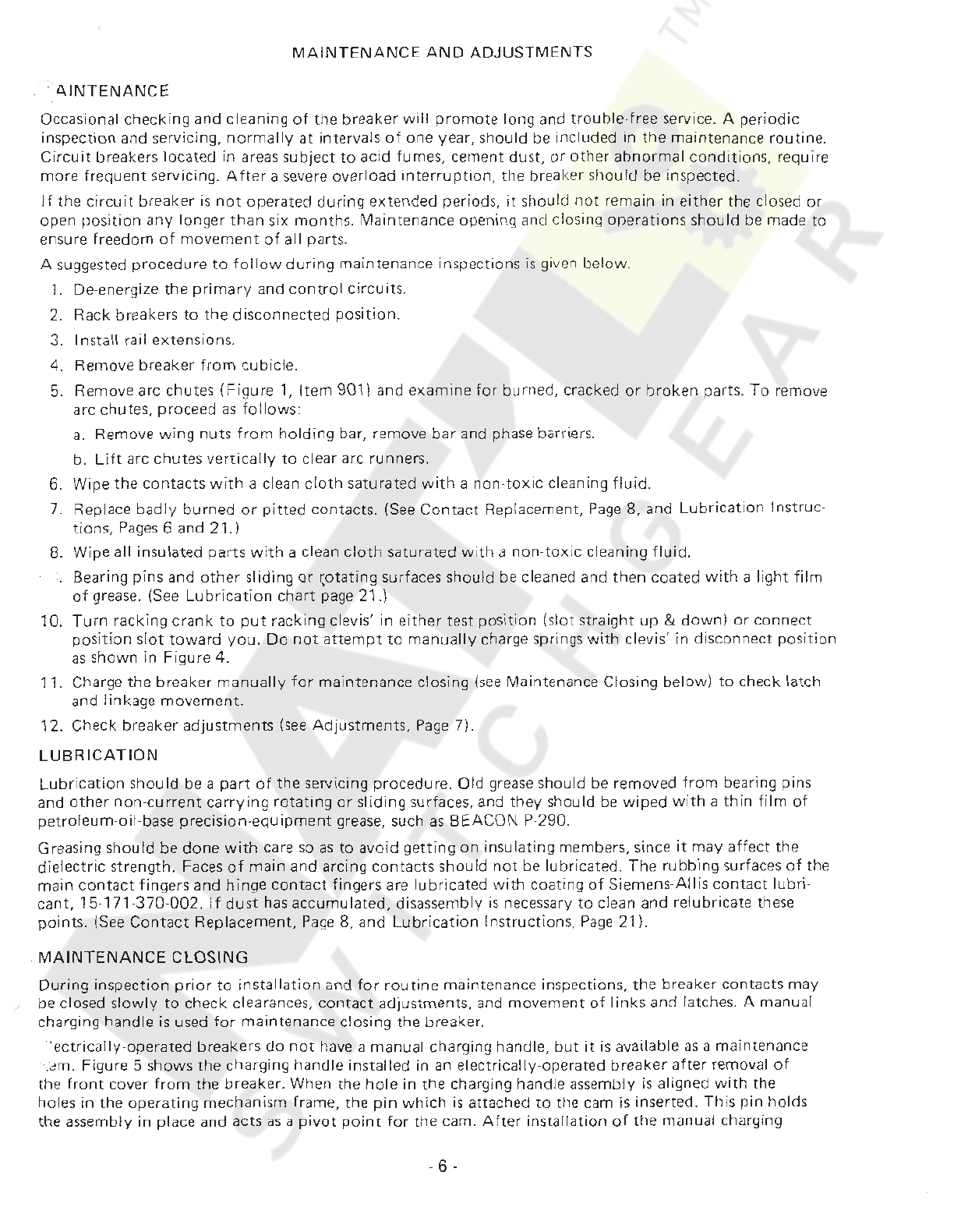
AINTENANCE
Occasional checking and cleaning
of
the breaker
will
promote
long and
trouble
-free service. A per
iodic
inspection and servicing,
normally
at
intervals
of
one year, should
be
included in the maintenance
routine.
Circuit
breakers
lo
cated in areas subject
to
acid fumes, cement dust,
or
other
abnormal
conditions,
requir
e
mo
re
frequent servicing.
After
a severe overload
interruption,
the breaker should be inspected.
If the circu
it
breaker
is
not
operated
during
extended periods,
it
should
not
remain in
ei
ther the closed
or
open
position
any
longer than s
ix
months
. Maintenance opening and closing operations sho
uld
be
made to
ensure freedom
of
movement
of
all parts.
A suggested procedure
to
follow
during
main
te
nance inspections
is
given below.
1. De-energize the
primary
and
contro
l circuits.
2. Rack breakers
to
the
disconnected
position.
3. Install rail extensions.
4. Remove breaker from cubicle.
5. Remove arc chutes
(Figure
1, Item 901) and examine for burned, cracked
or
broken
parts.
To
remove
arc chute
s,
proceed
as
follows:
a.
Remove
wing
nuts
from
holding
bar, remove
bar
and phase barriers.
b.
Lift
arc chutes
vertically
to
clear arc runners.
6. Wipe the
contacts
with
a clean
cloth
saturated
with
a non-
toxic
cleaning
fluid.
7. Replace
badly
burned
or
pitted
contacts.
(See
Contact
Replacement,
Page
8, and
Lubrica
tion
lnstruc·
tions,
Pages
6 and
21.}
8. Wipe all insulated parts
with
a clean
cloth
saturated
with
a
non-toxic
cleaning
fluid.
Bearing pins and
other
sliding
or
~otating
surfac
es
should be cleaned and then coated
wit
h a light
fi
lm
of
grease.
(See
Lubric
ation
chart
page 21.)
10.
Turn
racking
crank
to
put
racking clevis' in
either
test
position
(s
l
ot
straight
up
&
down}
or
connect
position
slot
toward
you.
Do
not
attempt
to
manually
ch
arge
springs wi
th
clevis' in disconne
ct
position
as
shown in Figure 4.
11. Charge
the
breaker
manually
for
maintenance closing (
see
Maintenance Closing below)
to
check latch
and linkage
movement.
12. Check breaker
adjustmen
ts
(see
Adjus
tments
,
Page
7).
LUBRICATION
Lubric
atio
n should be a
part
of
the servicing procedure. Old
grease
should be removed
from
bearing pins
and
other
non-current
carry
ing
rotating
or
sliding surfaces, and
they
should
be
wiped
with
a
thin
f
ilm
of
petroleum-oil-base precision
-equipment
grease, such
as
BEACON P-290.
Greasing should be
done
with
care
so
as
to
avoid
getting
on
insulating members, since
it
may
affect
the
dielectric strength. Faces
of
main
and arcing
contacts
should
not
be lubricated.
The
rubbing
surfaces
of
the
main
contact
fingers and hinge
contact
fingers are
lubricated
with
coating
of
Siemens-
Allis
contact
lubri-
cant,
15
-
171-370-002.
If
dust
has
accumulat
ed, disassembly
is
necessary
to
clean and relubricate these
points.
(See
Contact
Replacement.
Page
8, and Lubric
ation
Instructions.
Page
21).
.
MAINT
ENA
NCE
CLOSING
During
inspection
prior
to
instal
lation
and
for
routine
maintenance inspections. the breaker contacts may
be
closed
slowly
to
check clearances,
contact
adjustments, and movement
of
links
and latches. A manual
charging handle
is
used
for
maintenance closing the breaker.
"
ectrically
-operated breakers
do
not
have a manual charging handle,
but
it
is
available
as
a maintenance
-.
~m.
Figure 5 shows the charging handle ins
ta
lled in an electrically
-o
perated breaker
after
removal
of
the
front
cover
from
the breaker. When the
hole
in the charging handle
as
s
embly
is
aligned
with
the
holes in the
operating
mechanism frame, the
pin
which
is
attach
ed
to
t
he
cam
is
inserted. This
pin
holds
the assembly in place and acts
as
a
pivot
point
for
the cam.
After
installation
of
the manual charging
. 6 .
Courtesy of NationalSwitchgear.com

handle assembly on the electrically·operated breaker, the actual maintenance closing
operation
is
the
same
for
hath
the electrically-operated breaker and the man
ually
·operated
br
eake
r.
Refer
to
Table 3
and Figure 5.
CAUTION
II
TH
E
PROCEDURE
IN T
ABL
E 3
SHOULD
BE USED FOR
MAIN
TE
NAN
CE
C
LOSING
O
NL
Y.
MAIN
TA IN A FIRM
GRIP
ON THE
MANUAL
CHARGING
HANDL
E
DURING
TH
E
CLO
S
ING
STROKE
-
TH
E
BREAKER
MAY
SUDDEN
LY
LATCH
F
ULLY
CLOSED
AN
D APPLY
UNEXP
EC
TED
FOR
CE
TO
THE
CHARGIN
G
HANDLE
.
TA
BLE
3 -
MA
I
NTENANCE
CLOSIN
G (
Ref
er
to
Figure 5)
CAUTION!!
TU
RN
RA
CKI
NG
CRANK
TO
PUT
RA
CKING
CLEVI
S' IN
EITHER
TEST
POSITION
(
SL
OT STR
AIGHT
UP &
DOWN)
OR
CONNECT
POSITION
SLO
T
TOWARD
YOU
.
DO
NOT
ATTEMPT
TO
M
ANUALLY
CHARG
E SPRINGS
WITH
CLEVIS'
IN DISCONNECT
PO
SITI
ON AS SHOWN IN FIG. 4.
Operation
Closing Contacts
Procedure
1.
P
ull
charging handle DOWN A
LL
TH
E
WAY
(a
ppro
x
imately
120
°)
, and
hold
handle
down.
2.
Pl
ace
blade
of
screwdriver between
ho
od and
sp
ring
release latch a
nd
hold
it
in
this
position.
T
hi
s prevents
sp
rings
from
latching in charged pos
itio
n,
or
se
e
no
te
below
.
3. S
low
ly
return handle
to
vertical position. Observe
cont
act,
touch,
mechanical
op
era·
tion,
etc.
4.
Re
move screwdriver a
nd
pull charging handle
to
the
fully
charged
posit
ion. All
ow
sp
ring release latch
to
hold
closing springs. Move chargi
ng
handle
to
th
e
verti
ca
l
po
s
it
ion.
5. C
lo
se
breaker
norm
a
lly
by
pressing
clo
se
hoo
d.
Opening Contacts Push
in
manual
trip
rod.
NOTE
:
Holding the spring rele
ase
latch
down
prevents the stored
-ene
rgy springs
from
propping in the charged posi-
tion.
Th
us
,
when
th
e handle is s
lowly
returned
to
the n
orm
al v
ert
ical
position,
th
e energy in
the
springs
is
slowly
rele
ased
against
th
e
clo
sing handle assembly cam fac
e.
•
ADJUSTMENTS
D
ur
ing maintenance inspections,
the
following
items should
be
checked
to
ensure
that
the
or
iginal
se
ttin
gs
are maintained:
Trip
Latch
Engagement
(Figur
e 2)
Togg
le
latch (
175)
should eng
age
th
e fu
II
wi
dth
of
tr
ip
l
atc
h (1
53A
)
when
the
breaker is closed in the
nor·
mal manner.
The
tension
on
spring (
155
) can be increased if required
by
bending spring tab on
tr
ip
flap
to
·
wards the
front
of
the breaker.
Too
much tension
will
interfere
with
the
cap
ab
ili
ty
of
the
tripping
actuator
to
move the
trip
flap,
so
over-bending s
houl
d be avoided.
Main
Contact
Make (
Figur
e 6)
Compression
of
cont
act
fingers (58) should be between
.093
inch
es
and
.12
5 inches.
This
is
the difference
in
the
measurement
from
the
breaker b
ase
to
the
tip
of
the
fin
ger
contact
surface
when
the breaker is open
a
nd
the
measurement in
th
e
sam
e pla
ce
wh
en
the
breaker
is
clo
sed.
This
is
checked
with
a normal closing
operation
-
not
maintenan
ce
clo
sing.
Adjust
me
nt
is
provided
by
positioning
screws (85)
aft
er loosening
nuts
(86).
Cou
nte
rc
loc
kwise
ro
t
ation
of
scr
ew
s (
85
) increasescompression.
Ca
re
should be tak
en
to
re
tight-
en
nuts
(86)
after
adjustment.
If
it
is
desired
to
check
contact
pressur
e,
a push·
type
spring scale
can
be
us
ed
to
compress
contact
fin
gers (
58
),
with
breaker open.
Contact
pressure should be
betw
een
20
to
30
pounds
on each finger.
Arci
ng
Contact
Make
(Figure 6)
With
movable ar
ci
ng
contact
(73) in any one phase
touching
the
mating
station
a
ry
contact
when the break-
er
is
closed
by
the
maintenance closing
method
(
See
Table
3, Fig. 5),
the
phase-to-phase variation should
not
,exceed .
062
inches.
Adjustment
may
be made
by
positioning
screws
(85)
as
in
the
pr
evious paragraph,
- 7 -
Courtesy of NationalSwitchgear.com
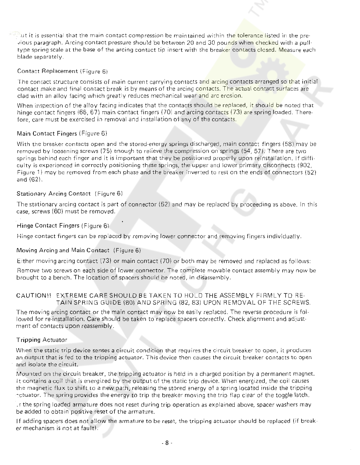
·
..
ut
it
is
ess
ential
that
the
main
cont
act
com
pression
be
maintained w
ithin
t
he
tolerance listed in the pre-
vious paragraph.
Arcing
conta
ct
p
re
ssure should be between 20
an
d
30
pound
s when checked
with
a pull-
type
spring
scale
at
the
base
of
the arcing
contact
tip
insert
with
the breaker contacts closed. M
eas
ure each
blade
se
parately.
Conta
ct
R
ep
l
ac
ement
(Figure 6)
The
contacl
structu
re
consists
of
main
cur
rent
carrying contacts and arcing
contac
ts arranged
so
that
initial
contact
mak
e and final
contact
break
is
by
means
of
the arci
ng
contacts. The actual
contact
surfaces are
clad wi
th
an al
loy
facing
which
greatly
redu
ces
mechanical wear and arc erosion.
When inspection
of
the all
oy
facing indicates
th
at the contacts should be replaced,
it
should
be
noted
that
hinge
cont
act fingers (
66,
67) main
contact
fingers (70) and arcing contacts (73) are spring loaded. There-
fore, care
must
be exercised in removal and install
ation
of
a
ny
of
the contacts.
Main
Cont
act Fingers
(Figure
6)
With
the breaker
contact
s open and
th
e stored-energy spri
ngs
di
sc
harged, main
contact
fingers (58)
may
be
removed
by
loosening scr
ew
s (75) enough
to
relieve
the
compr
ession on springs (54, 57).
The
re
a
re
two
springs behind each finger
and
it
is
important
that
they
be
positioned
properly
upon
reinstallation. If
diffi-
culty
is
experienced in
correctly
positioning
t
hese
springs, the
upper
and
lower
prim
ar
y disconnects (
902
,
Figure 1) may
be
removed
fr
om
each phase and the breaker
inv
erted
to
rest
on
the ends
of
connec
to
rs
(52)
and (62).
Stationary
Arcing
Cont
act
(Figure 6)
The
stat
ionary
arcing
contact
is
par
t
of
connector
(52) and
may
be
re
pl
ac
ed
by
proceeding
as
above.
In
this
case, scre
ws
(60)
must
be
rem
oved.
rlinge
Con
tact
Fingers (Fig
ure
6)
Hinge
co
ntact
fingers can be replaced
by
removing lower
co
nnector
and removing fingers
individua
lly.
Moving
Arcing
and Main
Contact
(Figure
6)
Eithe
r moving arcing
cont
ac
t (73)
or
main con
tact
(70)
or
both
may
be
re
moved and replaced
as
foll
ows:
Remove
two
screws on each side
of
lower
connector.
The
comp
lete movable
conta
ct
assembly
may
n
ow
be
bro
ught
to
a bench. The loca
tion
of
spacers s
hould
be noted, in disa
sse
mbly.
CAUTION!!
EXTREME
CARE
SHOU
LD BE
TAKEN
TO H
OLD
THE
ASSEMBLY
Fl
RMLY
TO
RE
·
TAI
N
SP
RING
GUIDE
(80)
AND
SPRING (82, 83) U
PO
N
REMOV
AL
OF
TH
E
SC
REWS.
The
moving
arcing
contac
t
or
the
main
contact
may
now
be easily replaced.
The
rev
erse
procedure
is
fol-
lowed
for
re-installation. Care should be taken
to
replace spacers corre
ct
ly. Check align
ment
and adjust·
ment
of
con
tact
s
upon
reassembly.
Tripping
Actuator
Wh
en
the static trip device
sen
ses
a
circuit
condit
ion
that
re
quires the
cir
cu
it
breaker
to
open, it
pro
duces
an
output
t
hat
is
fed
to
the
tripp
ing
actuat
or.
Th
is
device then causes the
circuit
breaker
conta
cts
to
open
and isolate the circ
uit.
Mounted
on
the c
ir
cuit
breaker,
the
tripping
actu
ator
is held in a cha
rge
d
position
by
a perman
ent
magnet.
It
contains a coil
that
is
energized
by
the
output
of
the static
trip
device. Wh
en
energized, the
coil
causes
the m
ag
netic
flu
x
to
sh
ift
to
a
new
path,
releasing
the
stor
ed
energy
of
a spring located inside the tripping
-:
c
tuator.
Th
e spring provides
the
en
ergy
to
trip
the breaker moving the
tr
ip flap clear
of
the toggle
la
tch.
.r the spring lo
ad
ed
arma
tu
re
does
not
reset
during
trip
operation
as
explain
ed
abov
e,
spacer washers may
be added
to
ob
tain positive reset
of
the arm
at
ure.
If
adding
space
rs
does
not
allow
the
armatu
re
to
be
res
et, the t
ripping
actua
tor
should be replaced
(i
f break·
er mechanism
is
not
at
fault
).
. 8 .
Courtesy of NationalSwitchgear.com

N
OT
E:
Do
not
at
t
empt
to
disassemble the
tr
ippi
ng
actuator
as th
is
may
destroy
the
magnetic fie
ld
set-
up
by
the
permanent magnet and
wil
l render
the
actuator latch inopera
ti
ve u
nt
il remagnetized.
When repl
ac
ing a
tri
ppi
ng
act
u
ator
, the coil leads must be connected to
the
ter
minal
block
of
the st
at
ic
trip
in
the
correct polarity relationsh
ip
.
The bla
ck
l
ea
d of coil
must
be co
nn
ected
to
terminal 7 (negative) a
nd
th
e
reel
lead
of
coil conn
ec
ted
to
te
rmi
nal 8 (positive)
of
the static
trip
device.
Wh
en
th
e
trip
ping actu
ator
has been rep
la
ced, the circuit bre
ak
er s
hould
be
giv
en
a FUN
CT
ION TEST to
en
su
re
proper
operat
io
n
of
all
com
pon
ents. Re
fe
r to Siemens-Allis I
nstr
uction
Book
18X4827
for
the
pr
ocedures
of
th
e F
UN
CTI
ON
TE
ST.
Motor
C
utoff
Sw
it
ch
es
The
fun
ct
ion and a
djust
me
nt
of
t
he
motor
cut
o
ff
swi
tc
hes
on elec
tr
ic
ally
-o
pe
rated
br
eakers is described on
P
age
10
.
-9 -
Courtesy of NationalSwitchgear.com
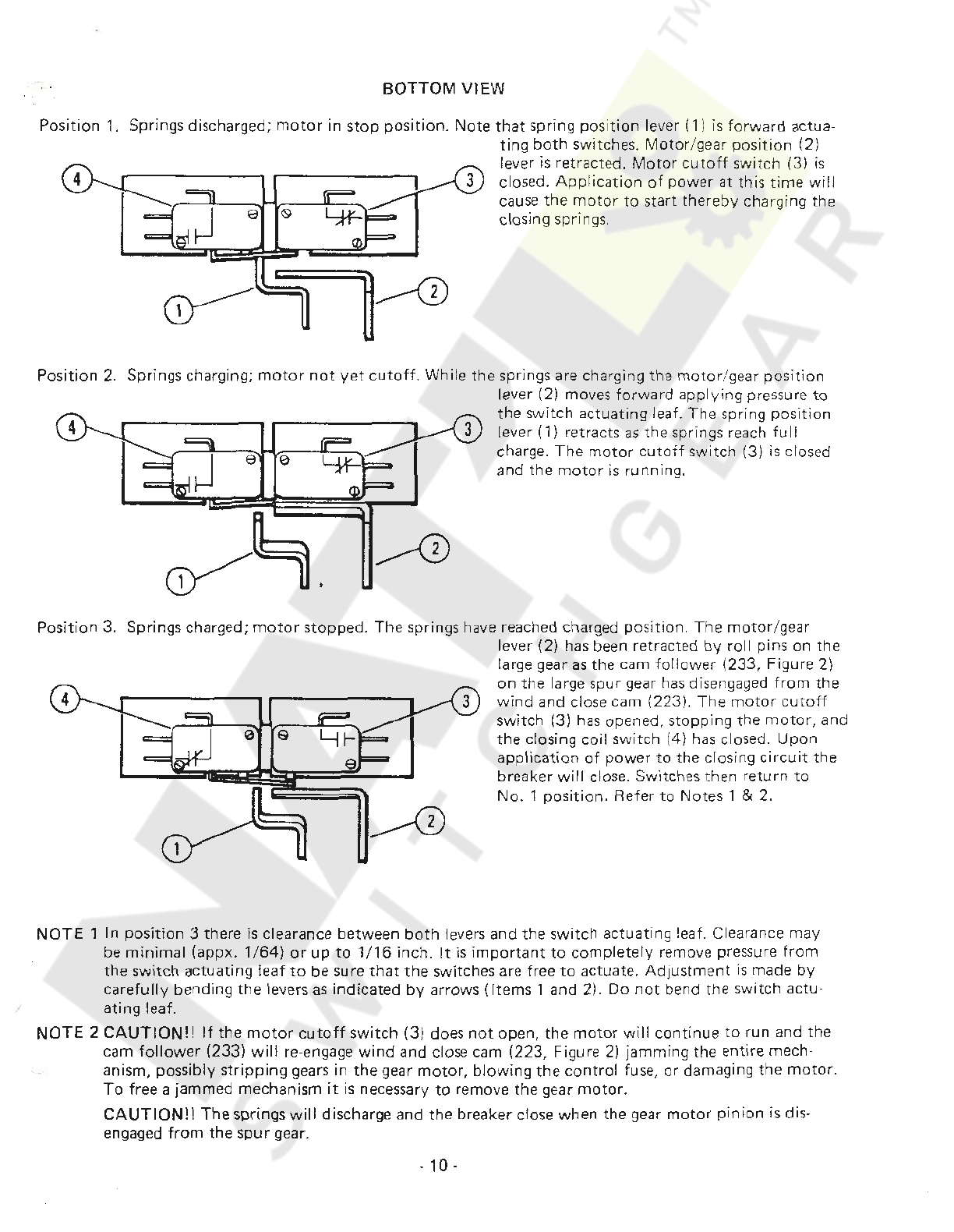
P
osition
1.
Position 2.
Posi
tio
n 3.
BOTT
OM VIEW
S
pr
in
gs
discharged; motor in s
top
po
sition.
Note
that
spring pos
it
ion lever (1) is f
or
ward actua-
ting
both
switches.
Motor
/gear
position
(2)
lever
is
retracted.
Motor
cutoff
switch (3)
is
closed.
Application
of
power
at
this
time
will
cause the
motor
to
sta
rt
thereby charging the
closing springs.
Spri
ngs
charging;
mo
to
r
not
yet
cuto
ff.
While the spri
ngs
are charging the
motor
/
gea
r
po
s
iti
on
lever (2) moves
for
ward
applying
pressure
to
the switch actuating leaf.
Th
e spring
position
lever (1) retracts
as
the springs
re
ach fu
II
charge.
The
mot
or
cutoff
switch
(3) is closed
and the
motor
is
runn
ing.
Spri
ngs
char
ged
;
mot
or
stop
ped. The
sp
rings have reached charged p
os
ition.
The
mot
o
r/
g
ea
r
l
eve
r (2) has been retracted
by
ro
ll pins on
the
la
rge
gear
as
the cam
fo
ll
ower
(233, Figure 2)
on
the large spur gear
has
disengaged
from
the
wind
and close cam (
223
).
The
m
otor
c
utoff
s
wi
tch (3)
has
opened,
stopping
the
motor,
and
the closing coil s
wi
tch (4)
has
closed.
Upon
app
lication
of
power
to
the closing c
irc
u
it
the
br
ea
ker
will
cl
os
e.
Switches
the
n retu
rn
to
No.
1
position.
R
efer
to
Notes 1 & 2.
NOTE
1
In
position
3 there isclearance betwe
en
both
levers and the
switch
actuating leaf. Clearance
may
be
minimal
(appx. 1/
64)
or
up
to
1/16
inch.
It
is
important
to
completely
remove pressure
from
the
switch
actuating
leaf
to
be sure
that
the
switches are free
to
actuate. A
djustment
is made
by
ca
ref
ully
bending
th
e levers
as
indi
cated
by
arrows
(It
ems 1 and 2).
Do
not
bend the switch actu-
a
ting
leaf.
NOTE
2
CAUTION!!
If the
motor
cu
toff
switch
(3) does n
ot
open, the
motor
will
continue
to
run and the
cam
fo
llower
(233) w
ill
re
-engage
wind
a
nd
close
ca
m (223, Figure 2)
jamm
i
ng
the entire mech-
an
is
m,
possibly str
ipping
gears in
th
e gear
motor,
bl
o
wing
the
control
fuse,
or
damaging the
motor.
To
free a jammed mechanism
it
is n
eces
sary
to
remove the gear
motor.
CAUTION!!
The springswill discharge and the breaker close when the gear
motor
pinion
is dis-
engaged
fr
om
the
spur
ge
ar.
. 10 -
Courtesy of NationalSwitchgear.com

ACCESSORIES
Tripping
Transformers
-
Static
Trip
11
There are several
tripp
ing transformer ratings available, each
with
seven
ca
li
brated
pickup
sett
in
gs
(Page
12).
The
tr
i
pping
transformers
are
mounted
on
the
lower
connector
and
mounted
with
the pol
arity
mark
facing
the breaker panel.
Current
Sensors -
LimiTrip
The
current
sensors
provided
with
the
optional
LimiTrip
device are integrated
units
containing
two
cores
with
four
terminals.
Proper
polarity
is
established when the terminals face away
from
the panel. Li
miTrip
sensors should never be subjected
to
primary
current
with
the
LimiTrip
device disconnected
from
the
sensor.
OPTIONAL
DEVICES
Secondary
Disconnect
Assembly
Option
The electrical
attachments
are
wired
to
the
termina
ls
of
a secondary
disconnect
assembly (
See
Figure 7),
which
is
mounted
on
the
left
side
of
the
breaker.
Thre
e
blocks
of
ten
terminals
each
can
be
mounted
on
the
breaker.
The
secondary
disconnect
assemb
ly
is
accessible
from
the
front
of
the
breaker and aligns
with
a
stationary
unit
in
the
cubicle.
The
stationary
contact
strips should be
lubricated
with
a l
ight
fi
lm
of
con-
tact
grease
which
is
furnished
with
the
switchgear.
Auxiliary
Switch
Option
The
auxiliary
switch
(See Figure
8)
is
of
the
rotary
type
and
functions
by
direct
connect
to
the
breaker
mechanism.
The
contacts
are
factory
set
for
"a"
(open when
the
breaker
is
open) and
"b"
(closed when
the
breaker
is
open)
position,
but
each
rotor
(955)
may
be adjusted
individually
in
steps
of
30
degrees.
This
adjustment
is
made
by
removing cover
(962)
and
lifting
the
entire
rotor
assembly
out
of
case
(950)
after
disconnecting
arm
(957)
from
the
linkage.
Cotter
pin
and bearing
(956)
are removed
to
perm
it
re-
moval
of
rotors
(955)
from
shaft
(954).
To
change
rotors
(955)
from
"a"
to
"b"
position,
the
rotor
should
be
rotated
60°
in
the
clockwise
direction
aher
removal and replaced
on
the
shaft
in this new
position.
Shunt
Trip
Option
Each el
ectrically
-operated
breaker
is
equipped
with
a
shunt
trip
attachment
for
tripping
from
a
remote
l
ocation.
(See Figure
9).
Since
the
shunt
trip
coil
is
designed
for
a
momentary
duty
cycle,
an
"a"
auxiliary
contact
switch
is
used
to
interrupt
its
circuit
immediately
after
the
breaker
is
tripped.
Energization
of
the
coil causes
the
armature
to
pick
up
and
rotate
the
trip
latch
to
trip
the
breaker. A compression spring (808)
ret
urns
the
ar
mature
to
its
norma
l
position
.
Undervoltage
Trip
Device
Option
The undervoltage
trip
device
(Figure
10)
automatically
trips
the
breaker
on l
oss
of
voltage.
Either
instan-
taneous
or
time
-
delay
operation
can
be
supplied. A
.06
inches gap
should
be maintained between
flap
ex-
tension and
pull
link
(738)
when
the
device
is
energized
with
the
breaker closed. Pick-up and
drop-out
is
set
so
that
the
device
picks
up
at
a voltage
of
85%
or
less
of
rated value and
drops
out
between 30% and
60%
of
the
rated value.
NOTE:
Pick-up and
drop-out
are
not
ind
iv
idually
adjustable.
Bell
Alarm
Switch
Option
The
bell alarm
switch
option
(See Figure 11)
functions
to
operate a
switch.
A single
pole
double
throw
or
a
double
pole
double
throw
switch
is
available.
The
switch
operator
is
connected
to
and
is
operated
by
the
tripping
actuator.
The
switch
operator
remains
tripped
even when
the
actuator
is
reset
by
the
breaker. The
switch
operator
must
be reset
either
manually,
or
by
an
additional
optional
electrical reset solenoid.
The
contacts
of
the
bell
alarm
switch
can be connected in series
with
the
breaker
closing
coil,
to
provide
a
lockout
feature
to
prevent
reclosing
after
a
fault.
-
11
-
Courtesy of NationalSwitchgear.com

-·
TABLE
4 -
TRIP
RATING
TABLE
-
AMPERES
STATIC
TRIP
II
Breaker
Tripping
Long
Time
Element
Ground
Element
Type
and
XFMR
Calibrated Pick-Up Settings Max.
Ca
lib
rated
Pick-Up
Frame
Rating
Cont
.
Setting
s
Size (Primary) A B c D E F G Rating 1
5%
25
% 50%
100
%
LA-3200A
2000
Amps
1000
1250
1500
1750
2000
2250
2500
2500
300
500
1000
2000
LA-3200A
3200
A
mp
s
1600
200
0 24
00
2800
3200
3600
4000
3200
480
800
1600
3200
LA-4000A
4000
A
mp
s
2000 2500
3000 3500
4000
4500
5000
4000
600
1000
2000
4000
&8
TABLE
5 -
TRIP
RATINGS
-
AMPERES
LIMITRIP
Breaker
Tripping
Lon
g
Time
Element
Type
and
XFMR
Calibrated Pick-Up Settings Max.
Fram
e
Rating
Co
nt
.
Size (
Primary
) A B c D E F Rating
1
.A-3
20
0A
2000
Amps
1000
1250
15
00
1750
20
00
2250
2250
_A-
3200
A
3200
Amps
16'o0
2000
2400
2800
3200 3600
3200
LA-4000A
4000
Amps
2000 2500
3000
3500
400
0
4500
4000
&8
Static
T
rip
Op
ti
on
The
opt
ional
tripping
devi
ces
are covered in detail
un
der
their
own
instruction
books which are
ref
erenced
on
the last page. Several types are available
that
provide a range
of
tripp
ing functions.
The
Stat
ic
Trip
11
device
mounts
on
to
a slide
type
bracket
on
the
circ
uit b
rea
ker.
To
remove
trip
device,
the
terminal
block
cover located above the
trip
device should be removed, exposing the
term
in
al
block
screws.
The
lower
r
ow
of screws can be
loo
sen
ed
with
a scr
ew
driv
er,
al
l
owing
the terminal
bloc
k fanning
strip
from
the static
trip
to
be
re
mov
ed
from
the terminal
block.
Removal
of
the fanning
strip
exposes a
mounting
screw.
Th
is
screw can be removed
allowing
the static
trip
device
to
be removed
from
the breaker
by
pulling
the
tr
ip device
towards
the
front
of
t
he
br
ea
ker
.
. 12 .
Courtesy of NationalSwitchgear.com

w
902~1
DETAIL
'
D"
~
:
!
,
I
··-) '
.1
1 1,
I
I
1,
I
I
'·
I"
I 01
11
C0
1
..
~
1:.
1'd 1·
I I 1lt
I
•I
1
11
;
I 1
11
.
' 1'
I , 1 1
11
278
I '-I
II
I I I I
"
~
'-;,
.
-..- -
I
~
11 1
II
I
~
~
.
l
l.,
I Ill
~
:l}{J'·J
~
:
t
g
1©
===:
y
--~:iff
·
~
r-
=
"~
~-~
~
··=
1
~
,
...
~L!J
4l
~
LH
SIDE
VIEW B
12-
901
13
0 0
RH
SIDE VIEW C
240
241
0
,--
1
--\
J_
___
L
----·
I
--902
0
0
~
~
u
SECTION
"
AA"
'
~ 0
'-sy
li'L--
1-
~
'
t
~
6
I \
\
113
241
240
•
.::
.....
ill
0 v
~
-
·
1
J~·
L_;_
''"'
'M
'-J
I
t=
~~
-
··
FRONT
VIEW
A
Fig. 1 -
LA
-
3200A
Circuit
Breaker
Courtesy of NationalSwitchgear.com

~
~<
181
/
~w
DETAIL
"A"
\
153A
' 175
s~
i
-
0~-~I
DE
TAI
L
"B"
,::;
--
0'
J
.-
_)
ur
ll
DETAIL
"C"
231
:.:
:~
168
VIEW
AA
VIEW
EE
215
171
,
LH
S
ID
E
VIEW
FRONT
VIEW
155
l-
3
VIEWFF
~
cr-14
--
· .
15
38
Fi
g.
2 -
Operator
/148
\.
VIEWD
E
223
233 224
RH
SIDE
VIEW
1 1
224
--.:_
-·--
LU.
!..-
':J-,
c::
...
..
.
;1":
·
·;7
...
.
~
VI
EW
HH
I!I
16
1
~
I
~
.J
l
jj
•
F
-
-.....
,
1155
.
~J
j,.
:
t•
-1
'
...;:./
-
L"
-
-:.::f'=r -
Courtesy of NationalSwitchgear.com

-
~---
-
----
--
--
---
----
--
~-
-
~
---
•
-
r
- ~
I I
LJJ..
_w
'--
r - - -
1---
--
-
-.
--
i i
I
~
'
r1
, I
I
..l..c
sc
1 1 1 '
...Lc
sr
I
l,..J
c,.
J T
I T ,-
...
,...J,
I I G \ I R 1 I
I ' / ' , I
I I T
.,.
~
l
J.
,
h.~
2
y~
I
r-!l=]
}-- -
---
---
-
-
~
--
- - I
2
I
---4----
----
- - -
--
- - - -
----
...
--
SY
MB
OL
S
SD
10
?
°SY
°JV
°6V
~
~
°3V
Q-'
;"v
~
~
SEC. DISC.
S
TD
STA
T IC
TR
IP
DEVICE
AS
f.1
f3fsf7
T a
bT
a b
6 2 4
66
8
AUX.
SWI
TC
H
CC
- CI
RC
U
IT
BREAK
ER CLOS
ING
CO
IL
TC - CIRC
UIT
BREA
KER
TR
IP COi L
Y - AUX. CLOSING
REL
AY
- AN
TI
PUMP
M
CO
-MOTOR CUTOFF
SW
ITCH
88 - SPRING CHARGING M
OT
OR
CSC
-
CO
N
TROL
SWITCH -
CL
OSE
CONTACT
CST -
CON
TROL SWITCH -TR
IP
CO
NT
ACT
R - RED INDI
CA
TIN
G
LA
MP
G - GREEN INDI
CAT
ING
LAMP
a -
AU
X.
SWITCH -OPEN WHEN
BR
'KR. IS OPEN
b -
AU
X. SWITCH - CLOSED WHEN
BR'K
R. IS OPEN
Ml
- MECHANI
CAL
I
NT
ERLOC
K
CT -
CURRENT
TRA
NSF
ORME
R
STD - S
TATI
C
TRIP
DEVI
CE
AL
- AL
ARM
DEVICE
RC
-
ALARM
DEVI
CE
EL
EC
T.
RESET
COIL
TA
-TRIP
ACTUATOR
UV
-UNDE
RVOLTAGE
TRIP
COIL
CLASS C
WI
RI NG
NO. 14
WI
R
E.
(S
IS)
00·557·286·3
41
MCO
F
ig.
3 - Typical Wiring Diagram -Electrica
lly
Operated Breakers
. 15 .
Courtesy of NationalSwitchgear.com

Lift
Bar a
nd
Rail
Ext
ensions
The l
ifting
bar
connects
as
shown. Always l
ift
wit
h
ex
tr
eme
caution
to
preve
nt
damage
to
breaker.
In
part
i-
cular, wa
tc
h
that
the secondary disconnects clear
the
rail extension. References:
Lifting
bar assembl
y:
18-727-
837-501.
E
xtension
rail: 18-
193-732
·
502.
See
Pag
e 4.
...
=
·
-~
I
(0
LIFTING
BAR
---
r-:-..,,,-
-
----
-
-~
c0
~-
---
-
--
-
-.
LIFT
HERE
RACKING
CLEVIS
L
.
.::
;
_
......
....
-
...-
·
,.....,.
MECHANICAL
INTER
LOCK
SIDE
VIEW
B
FRONT
VIEW
A
I
I
..
..
SE
CTI
ON
BB
DETAIL
"A
..
Fig. 4 -
Typical
Racking Mechanism and
Dr
a
wou
t
Interlock
-16 -
Courtesy of NationalSwitchgear.com

HANDLING
INSTRUCTIONS
INSERTING
CIRCUIT
BREAKER
1.
Mount
extension
rails
(A)
as
shown.
Tighten
catches
(Bl
to
secure r
ai
l
s.
2.
Lower
circuit
breaker
onto
ra
il
s.
checking
wheel
align·
ment
to
ra
ils.
3.
Roll
breaker
to
disconnect
posit
ion
and
remove
exten
·
sion rails.
Safety
lock
(C) prevents accidental removal
of
breaker
from
cell.
4.
Use
crank
to
rack
breaker
into
cell.
5. Check panel
shutte
rs
(0)
for
free
movement
befor
e
closing panel.
.
17
.
'
REMOV
ING
CIRCUIT
BREAKER
1.
Mount
extension rails
to
un
it
as
described under. "
In·
serting
Circuit
Breaker."
2.
With
c
irc
uit
breaker in disconnect position. release
breaker
i
nterloc
k
and
pull
breaker
out.
3.
Pu
ll
on
safety
loc
k
handle
to
fully
release breaker
from
ce
ll.
4.
Roll
breaker
ou
t
onto
extension
rails and li
ft
free
of
unit.
Courtesy of NationalSwitchgear.com
This manual suits for next models
2
Table of contents
Other Siemens-Allis Circuit Breaker manuals


Popular Circuit Breaker manuals by other brands


Siemens
Siemens VT160 operating instructions

Leakomatic
Leakomatic M3i+ user manual

Doepke
Doepke DFS F Audio Series Installation and operating instructions

MAXGE
MAXGE MGB Series manual

Projoy Electric
Projoy Electric PEBS-S Instructions for installation and operation

Larsen & Toubro
Larsen & Toubro U-POWER Omega UW-MTX1.0 user manual