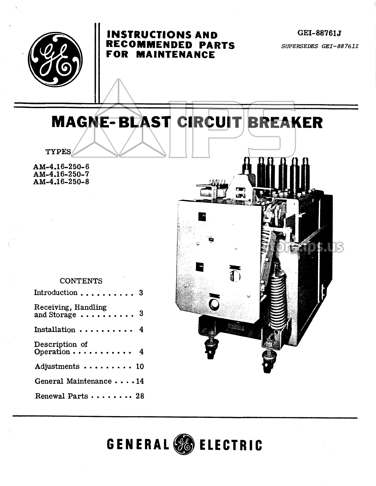
GE AM-4.16-250-6 User manual
Other GE Circuit Breaker manuals

GE
GE Shunt Trip User manual

GE
GE Power Break II User manual

GE
GE AM-13.8-500-7 User manual

GE
GE Rapid TripFix User manual

GE
GE AM-13.8-750-5 User manual

GE
GE AM-4.16-250-6C User manual

GE
GE AM-13.8-500-5A User manual

GE
GE AKR-30 Series User manual

GE
GE Spectra K-frame User manual

GE
GE POWER BREAK MICRO-VERSATRIP E39ME20 User manual


Popular Circuit Breaker manuals by other brands


Siemens
Siemens Sentron 3VA9157-0PK1 Series operating instructions

hager
hager TS 303 User instruction

ETI
ETI EFI-4B Instructions for mounting

nader
nader NDM3EU-225 operating instructions

TERASAKI
TERASAKI NHP TemBreak PRO P160 Series installation instructions

Gladiator
Gladiator GCB150 Installation instruction