Siemens Nixdorf SCENIC H User manual

Operating Manual
SCENIC H
The Intel Inside Logo is
a registered trademark
of Intel Corporation
Dieses Handbuch wurde auf Recycling-Papier gedruckt.
This manual has been printed on recycled paper.
Ce manuel est imprimé sur du papier recyclé.
Este manual ha sido impreso en papel reciclado.
Questo manuale è stato stampato su carta da riciclaggio.
Denna handbok är tryckt på recyclingpapper.
Dit handboek werd op recycling-papier gedrukt.
Published by
Siemens Nixdorf Informationssysteme AG
D-33094 Paderborn
D-81730 München
Order No.: A26361-K381-Z102-1-7619
Printed in the Federal Republic of Germany
AG 0695. 06/95
A26361-K381-Z102-1-7619

Orders
Software with manuals
Please send your order to the address given on the order form. You must include
the order form supplied and the relevant documents.
Backup disks
The backup disks contain the software stored on your hard disk, when the PC is
delivered. Please order from your sales partner.
A26361-K381-Z102-2-7619
Is there ...
... any technical problem or other ... anything you want to tell us
question you need clarified? about this manual?
Please send us your comments quoting
Please contact: the order number of the manual.
– one of our IT Service Shops
– your sales partner Siemens Nixdorf Informationssysteme AG
– your sales office User Documentation Department
BS2000 QM2, Otto-Hahn-Ring 6,
You will find the addresses of the 81730 München, Germany
IT Service Shops in the enclosed
warranty coupon booklet. Fax: (0 89) 6 36-4 04 43

Introduction
Important notes
Preparation for use
SCENIC H and operation
Settings in
BIOS setup
Protecting data
and property
Operating Manual Troubleshooting
and tips
Technical data
Index
June 1995 edition
Your training needs . . .
The Siemens Nixdorf Training Centers offer you a wide range of
training courses in information technology and on IT products and
other subjects - onsite near to your workplace or offsite at one of our
training centers.
Contact us for information on consulting, course schedules and
selfstudy material.
Please write or fax:
Siemens Nixdorf Informationssysteme AG
Training Center, Beratungsservice
D-81730 München
Fax.: ..49 89 636-42945
DPMS and VESA are registered trademarks of Video Electronics Association
Matrox is a registered trademark and Impression is a trademark of Matrox Electronic
System Ltd.
Microsoft, MS and MS-DOS are registered trademarks and Windows is a
trademark of Microsoft Corporation.
All other trademarks referenced are the trademarks or registered trademarks of
their respective owners, whose protected rights are acknowledged.
Copyright Siemens Nixdorf Informationssysteme AG 1995.
All rights, including rights of translation, reproduction by printing, copying or similar methods,
even of parts are reserved.
Offenders will be liable for damages.
All rights, including rights created by patent grant or registration of a utility model or design,
are reserved.
Delivery subject to availability.
Right of technical modification reserved.

Contents
Introduction 1
Notational conventions 2
Important notes 3
Safety 3
Manufacturer's notes 4
Transporting the PC 6
Class B 7
Important notice concerning power cord selection 8
For the United States and Canada 8
For the United Kingdom 10
Preparation for use and operation 11
Unpacking and checking the delivery 11
Preparing your PC for use 11
Setting up the PC 12
Connecting devices 13
Connecting external devices 14
Connecting the keyboard 14
Connecting a mouse 15
Connecting devices with serial or parallel interface 15
Connecting the monitor 15
Checking the rated voltage and connecting the power cable 16
Switching the system unit on and off 18
Switching on for the first time 19
Switching on the PC 20
Switching off the PC 21
Displays on the system unit 21
Working with floppy disks 22
Mechanical write protection 22
The keyboard 23
Key combinations 24
Cleaning the system unit 24
Reinitializing the hard disk 25
Code table of standard characters 26
A26361-K381-Z102-2-7619
Contents
Settings in BIOS Setup 27
Calling BIOS Setup 27
Operating BIOS Setup 29
Exiting BIOS Setup 30
Property and data protection 31
Preventing input with QLOCK 31
Using BIOS Setup Security functions 31
Setting the Setup password 33
Setting the system password 34
Troubleshooting and tips 37
The status indicator remains dark after you have switched on your PC 37
The screen stays blank 38
No screen display or display drifts 39
No mouse pointer displayed on the screen 39
The floppy disk cannot be read or written 40
Time and/or date is not correct 40
Error messages on the screen 40
Tips 40
Technical data 41
Index 43
A26361-K381-Z102-2-7619
Introduction
Your Personal Computer (PC) consists of a system unit, a monitor and the input
elements keyboard and mouse. The system unit normally contains one hard disk
drive and one floppy disk drive for storing data. You can also install additional
drives (e.g. CD-ROM drive, DAT drive) in the system unit. Depending on its
version, the system unit has one parallel interface and either one or two serial
interfaces.
To make it easier for you to set up the PC, the operating system, driver and
software utilities may have already be installed on the hard disk.
You can configure your PC in the easy-to-operate BIOS Setup.
Your PC is, of course, equipped with Plug&Play; it therefore recognizes and
automatically installs modules which support Plug&Play.
Your PC offers a range of security measures to prevent unauthorized persons from
accessing your data. The QLOCK program enables you to lock entry at your mouse
and keyboard. There are also security functions in the BIOS Setup, enabling you,
for example, to use passwords to protect access to your data.
The integrated power management ensures that your PC does not use more
energy than necessary. Depending on their settings, the monitor, the drives and
the processor can be switched to an energy-saving state. The entire PC can be
switched into an energy-saving state, if the PC supports the Save to Disk function.
Further information on this PC is provided:
– in the manual "Safety and ergonomics"
– in the Operating Manual for the monitor
– in the Technical Manual for the PC (describes installing and removing of
modules)
– in the Technical Manual for system board (describes system settings)
– in the MS-Windows INFO window (information on utilities and drivers)
– in the information files (*.TXT, *.DOC, *.WRI, *.HLP)
There are different variants of the system unit (for example, with main switch and
ON/OFF switch or with ON/OFF switch only, with three or five slots for modules).
These operating instructions are based on the variant with a main switch and five
slots for modules.
A26361-K381-Z102-2-7619 1
Introduction
Notational conventions
The meanings of the symbols and fonts used in this manual are as follows:
!Pay particular attention to texts marked with this symbol. Failure to observe
this warning endangers your life, destroys the system, or may lead to loss of
data.
This symbol is followed by supplementary information, remarks and tips.
i
Texts which follow this symbol describe activities that must be performed in the
order shown.
This symbol means that you must enter a blank space at this point.
↵ This symbol means that you must press the Enter key.
Texts in this typeface are screen outputs from the PC.
Texts in this bold typeface are the entries you make via the keyboard.
Texts in italics indicate commands or menu items.
"Quotation marks" indicate highlighted text and names of chapters.
2A26361-K381-Z102-2-7619

Important notes
In this chapter you will find information regarding safety which it is essential to take
note of with your PC. The chapter "Manufacturer's notes" contains helpful
information on your PC.
Safety
!Pay attention to the information provided in the manual "Safety and
ergonomics".
– During installation and before operating the PC, observe the instructions on
environmental conditions in the chapter entitled "Technical data" as well as the
instructions in the chapter "Preparing for use and operation".
– Please check whether the PC is set to the local power supply (see chapter
"Preparing for use and operation").
– The main switch and the ON/OFF switch does not disconnect the PC from the
line voltage. To disconnect the line voltage completely, remove the power plug
from the grounded power outlet.
– When cleaning the PC, observe the relevant notes in the chapter "Preparing for
use and operation".
– Before opening the PC first switch it off and then disconnect the power plug.
When opening the PC follow the instructions in the Technical manual of the PC.
The components (e.g. power supply) marked with a warning sign (e.g. lightning
flash symbol) may only be opened, removed or replaced by specialist
personnel.
– You may set only those resolutions and refresh rates specified in the "Technical
data" section of the monitor description. Otherwise you may damage your
monitor. If you are in any doubt, contact your sales office or customer service.
– The system board includes a lithium battery. Incorrect replacement of the lithium
battery may lead to a risk of explosion. It is therefore essential to observe the
instructions in the Technical Manual of the system board.
Do not throw lithium batteries into the trashcan. Your vendor or dealer or their
authorized representatives will take used batteries back free of charge so that
they can be recycled or disposed of in the proper manner.
A26361-K381-Z102-2-7619 3
Important notes
For Denmark
ADVARSEL
Lithiumbatteri - Eksplosionsfare ved fejlagtig håndtering. Udskiftning må kun
ske med batteri af samme fabrikat og type. Lever det brugte batteri tilbage til
leverandøren.
For Norway
ADVARSEL
Eksplosjonsfare ved feilaktig skifte av batteri. Benytt samme batteritype eller en
tilsvarende type anbefalt av apparatfabrikanten. Brukte batterier kasseres i
henhold til fabrikantens instruksjoner.
For Sweden
VARNING
Eksplosionsfara vid felaktigt batteribyte. Använd samma batterityp eller en
ekvivalent typ som rekommenderas av apparattillverkarenfabrikanten. Kassera
använt batteri enligt fabrikantens instruktion.
For Finland
VAROITUS
Paristo voi räjähtää, jos se on virheellisesti asennettu. Vaihda paristo
ainoastaan laitevalmistajan suosittelemaan tyyppiin. Hävitä käytetty paristo
valmistajan ohjeiden mukaisesti.
Manufacturer's notes
Energy Star
If there is an Energy Star symbol on the device, then:
This equipment fulfills the requirements of the US
Environmental Protection Agency (EPA) as set down in their
regulations and guidelines for energy-efficient computers (US
government initiative "EPA Energy Star Computers").
The EPA estimates that computer equipment uses 5 percent of all business
electricity and it's growing rapidly. If all desktop PCs and peripherals enter a low-
power mode when not in use, the overall savings in electricity could amount to $ 2
billion annually. These savings could also prevent the emission of 20 million tons of
carbon dioxide into the atmosphere - the equivalent of 5 million automobiles.
The EPA is pursuing the sole goal of promoting the idea of energy-saving. No
recommendations of individual companies or products are made.
4A26361-K381-Z102-2-7619

Important notes
Energy saving
– If you are not using your PC, switch it off.
– The QLOCK.COM (under MS-DOS) or the QLOCK.EXE or QLOCKWIN.EXE
(under MS-Windows) program enables you to lock entry at your mouse and
keyboard. If the attached monitor supports VESA power management (DPMS),
it is switched into energy-saving mode (see Operating Manual of the Monitor )
whenever entry is locked.
– In the BIOS setup you may set energy-saving functions for the PC. Further
information on energy-saving functions is provided in the Technical manual of
the system board.
Disposal and recycling
This equipment is made predominantly of materials that are suitable for
environmentally-friendly disposal or specialized recycling.
Devices marked with an environment symbol are taken back
after use, so that they or their materials can be recycled,
provided that they are returned in a condition which is the
result of normal use. Device parts which cannot be recycled
are disposed of in the proper manner.
Do not throw lithium batteries into the trashcan. Your vendor or dealer or their
authorized representatives will take used batteries back free of charge so that they
can be recycled or disposed of in the proper manner.
If you have any questions on disposal, please contact your local office, our service
department, or, directly:
Siemens Nixdorf Informationssysteme AG
Recycling Center
33094 Paderborn
Germany
Tel.: ..49 5251 - 720810
Fax.: ..49 5251 - 720815
A26361-K381-Z102-2-7619 5
Important notes
CE certificate
If there is a CE symbol on device, then:
This device complies with the requirements of the EEC directive
89/336/EEC with regard to "Electromagnetic compatibility".
Note on RFI suppression
All other devices connected to this product must have RFI suppression in
accordance with EC directive 89/336/EEC. Products meeting these requirements
are accompanied by a certificate issued by the manufacturer and carry the CE
symbol.
Transporting the PC
!Transport all parts separately, and in their original packaging or in a
packaging which protects them from knocks and jolts, to the new site. Do
not unpack them until all transport maneuvers are completed.
Never drop the monitor (danger of implosion)!
6A26361-K381-Z102-2-7619
Important notes
Class B
If there is an FCC B symbol on the device, then:
The following statement applies to the products covered in this manual, unless
otherwise specified herein. The statement for other products will appear in the
accompanying documentation.
NOTE:
This equipment has been tested and found to comply with the limits for a "Class B"
digital device, pursuant to Part 15 of the FCC rules. These limits are designed to
provide reasonable protection against harmful interference in a residential
installation. This equipment generates, uses and can radiate radio frequency
energy and, if not installed and used in strict accordance with the instructions, may
cause harmful interference to radio communications. However, there is no
guarantee that interference will not occur in a particular installation. If this
equipment does cause harmful interference to radio or television reception, which
can be determined by turning the equipment off and on, the user is encouraged to
try to correct the interference by one or more of the following measures:
– Reorient or relocate the receiving antenna.
– Increase the separation between equipment and the receiver.
– Connect the equipment into an outlet on a circuit different from that to which the
receiver is connected.
– Consult the dealer or an experienced radio/TV technician for help.
Siemens Nixdorf Informationssysteme AG is not responsible for any radio or
television interference caused by unauthorized modifications of this equipment or
the substitution or attachment of connecting cables and equipment other than
those specified by Siemens Nixdorf Informationssysteme AG. The correction of
interferences caused by such unauthorized modification, substitution or attachment
will be responsibility of the user.
The use of shielded I/O cables is required when connecting this equipment to any
and all optional peripheral or host devices. Failure to do so may violate FCC rules.
This digital apparatus does not exceed the Class B limits for radio noise emissions
from digital apparatus as set out in the interference-causing equipment standard
entitled "Digital Apparatus", ICES-003 of the Canadian Department of
Communications.
Cet appareil numérique respecte les limites de bruits radioélectriques applicables
aux appareils numériques de Classe B prescrites dans la norme sur le matériel
brouilleur: "Appareils Numériques", NMB-003 édicté par le ministre des
Communications du Canada.
A26361-K381-Z102-2-7619 7
Important notes
Important notice concerning power cord
selection
The power cord for this unit has been packed separately and has been selected
according to the country of destination. It must be used to prevent electric shock.
Use the following guidelines if it is necessary to replace the original cord set.
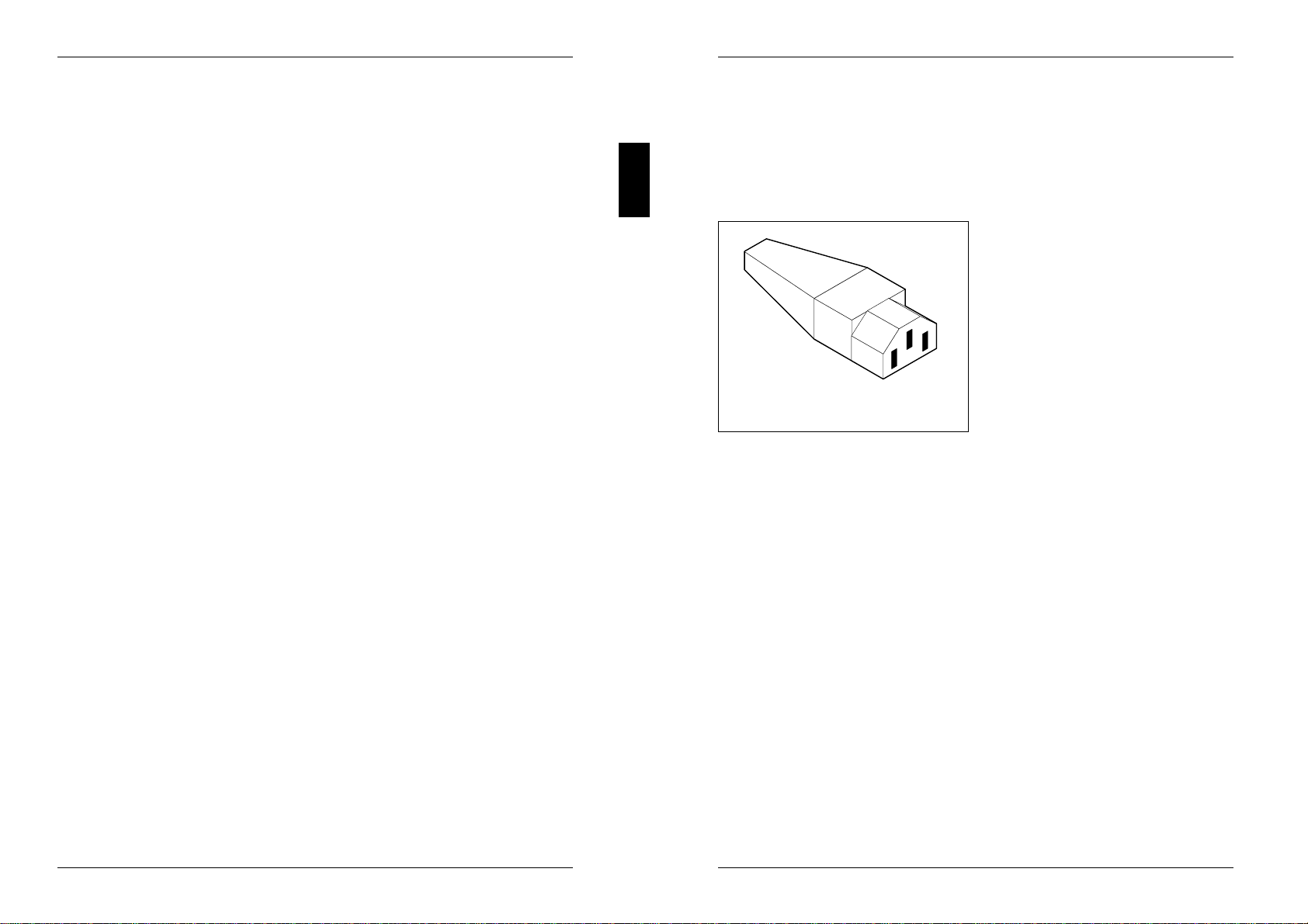
Figure 1
The female receptacle of the cord set
must meet CEE-22 requirements (see
Figure 1).
For the United States and Canada
Use a UL listed and CSA labelled cord set consisting of a three conductor cord with
a maximum length of 15 feet.
For units which stand on a desk or table, type SVT or SJT cord sets shall be used.
For units which stand on floor, only SJT type cord sets shall be used.
The cord set must be selected according to the current rating for your unit. Please
consult Table A for the selection criteria for power cords used in the United States
and Canada.
8A26361-K381-Z102-2-7619

Important notes
Table A:
Cord Type Size of Conductors Maximum Current
in Cord Rating of Unit
SJT 18 AWG 10 Amps
16 AWG 12 Amps
14 AWG 12 Amps
SVT 18 AWG 10 Amps
17 AWG 12 Amps
For units set at 115 V:
use a parallel blade, grounding type attachment plug rated 15 A, 125 V (Figure 2).
For units set at 230 V (domestic use):
use a tandem blade, grounding type attachment plug rated 15 A, 250 V (Figure 3).
Figure 2 Figure 3
For units set at 230 V (outside of the United States and Canada):
use a cord set consisting of a minimum AWG according to Table A and a
grounding type attachment plug rated 15 A, 250 V. The cord set should have the
appropriate safety approvals for the country in which the equipment will be installed
and should be marked HAR.
A26361-K381-Z102-2-7619 9
Important notes
For the United Kingdom
Should the plug on the flexible cord not be of the type for your socket outlets, do
not use an adapter but remove the plug from the cord and discard. Carefully
prepare the end of the supply cord and fit a suitable plug.
WARNING
THIS APPLIANCE MUST BE EARTHED
IMPORTANT
The wires in this mains lead are coloured in accordance with the following code:
Green and Yellow: Earth
Blue: Neutral
Brown: Live
As the colours of the wires in the mains lead of this appliance may not correspond
with the coloured markings identifying the terminals in your plug, proceed as
follows:
– The wire which is coloured Green and Yellow must be connected to the terminal
in the plug which is marked with the letter E or by the earth symbol or coloured
Green or Green and Yellow.
– The wire which is coloured Blue must be connected to the terminal which is
marked with the letter N or coloured Black.
– The wire which is coloured Brown must be connected to the terminal which is
marked with the letter L or coloured Red.
10 A26361-K381-Z102-2-7619

Preparation for use and operation
!Please take note of the "Important notes" at the beginning of this Operating
Manual.
Unpacking and checking the delivery
It is recommended not to throw away the original packing material! It may be
required for reshipment at some later date.
Unpack all the individual parts.
Check the delivery for damage incurred during transport.
Check whether the delivery agrees with the details in the delivery note.
Check whether all the necessary details have been entered on the guarantee
card or on the first page of the guarantee coupon booklet.
Should you discover that the equipment has been damaged during transport or that
the delivery does not correspond to the delivery note, notify your local sales office
immediately.
If you have received drives or modules with your PC, mount them before
iinstalling the PC. The technical manual for the PC will tell you how to do
this.
Preparing your PC for use
When preparing your PC for use, you should carry out the following steps in the
order given. If not otherwise specified, these steps are described in this section.
1 Set up the PC in the selected location.
2 Connect the devices to the system unit.
3 Check the rated voltage and connect the system unit to the power voltage.
4 Switch on the PC and follow the instructions on the screen.
A26361-K381-Z102-2-7619 11
Preparation for use and operation Setting up the PC
Setting up the PC
!When installing your PC, give consideration to the recommendations about
an ergonomic video workstation in the "Safety and ergonomics" manual.
We recommend that you place your equipment on a surface with good anti-
slip qualities.
In view of the multitude of different finishes and varnishes used on furniture,
it is possible that the PC's rubber feet will mark the surface it stands on.
Provide at least 200 mm of clearance on the left and behind the ventilator
area of the system unit to ensure adequate ventilation. Do not cover the
ventilation areas of the monitor and the fan.
Do not expose the PC to extreme environmental conditions (see the chapter
"Technical data"). Protect it from dust, humidity and heat.
The color monitor must not be exposed to strong magnetic fields
12 A26361-K381-Z102-2-7619
Connecting devices Preparation for use and operation
Connecting devices
The power plug must be pulled out!
!Read the documentation about the external device before connecting it.
Do not connect or disconnect cables during a thunderstorm.
Never unplug a cable by pulling the cable itself. Always take hold of the
actual plug body.
Connect and disconnect the cables in the order described below.
Connecting cables
– Turn off all power and equipment switches.
– Pull all power plugs out of the grounded-contact utility power sockets.
– Plug all cables into the system unit and peripherals. Please observe under all
circumstances the information provided in the chapter "Important notes".
– Plug all data communication cables into the utility sockets.
– Plug all power cables into the grounded-contact utility power sockets.
Disconnecting cables
– Turn off all power and equipment switches.
– Pull all power plugs out of the grounded-contact utility power sockets.
– Unplug all data communication cables from the utility sockets.
– Disconnect all cables from the system unit and peripherals.
A26361-K381-Z102-2-7619 13
Preparation for use and operation Connecting devices
Connecting external devices
The connectors for the devices are on the rear of the system unit.
123456
abcdefgh
1 = Keyboard port a = Keyboard port
2 = Mouse port b = Mouse port
3 = Serial interface 1 c = Serial interface
4 = Serial interface 2 d = Parallel interface
5 = Parallel interface e = Game port
6 = Monitor port f = Loudspeaker port
g = Audio input
h = Microphone port
You can set up the mouse port, the serial interface and the parallel interface
iin the BIOS setup.
If you want to use the VGA board "Matrox Impression" with MS-Windows
standard drivers, you must disable the audio function on the system board.
Some of the devices that you connect require special drivers (e.g. a printer
driver for the printer). For information on which driver you need to install and
where, please refer to the documentation for the device concerned.
Connecting the keyboard
Plug the connector of the keyboard
cable into the socket on the
underside of the external keyboard.
Connect the round plug on the
keyboard cable into the keyboard
port on the system unit.
14 A26361-K381-Z102-2-7619

Connecting devices Preparation for use and operation
Connecting a mouse
Connect the mouse to the mouse port.
Connecting devices with serial or parallel interface
Connect the data cable to the external device.
Connect the data cable from the external device to the appropriate interface on
the system Unit.
Connecting the monitor
Connect the data cable of the monitor to the monitor port of the system unit.
b
a
a
1
2
1 = System unit with main switch 2 = System unit without main switch
Depending on the connector, plug the monitor's power cable into either the
system unit (a) or the power outlet (b).
!If monitor power consumption is greater than shown in chapter "Technical
data", do not plug the monitor into the monitor socket on the system unit
(see technical data on the monitor casing or in the monitor operating
manual).
A26361-K381-Z102-2-7619 15
Preparation for use and operation Checking the rated voltage
Checking the rated voltage and connecting the
power cable
The changeover switch for rated voltage is located to the rear of the Docking Unit.
There are two different types of changeover switch.
1
2100 V - 120 V 200 V - 240 V
115
230
115
230
230
115
1 = Plugin unit at system unit with 2 = Wiper switch at system unit without
main switch main switch
!In the case of a plugin unit (1), the upper value (arrow) must agree with the
local line voltage. The rated voltage (115V or 230V) shown on the wiper
switch (2) must agree with the local line voltage.
Always check that the correct voltage has been set at the monitor, printer
and any other peripheral.
Rated voltage 115 V 230 V
Voltage range 100 V - 120 V 200 V - 240 V
Check the rated voltage and set up the correct value.
Plugin unit (1):
Lift out the plugin unit with a screwdriver, turn it and replace it.
Wiper switch (2): Move the wiper switch to the correct position.
16 A26361-K381-Z102-2-7619

Checking the rated voltage Preparation for use and operation
a
b
1
12
2
a = System unit with main switch b = System unit without main switch
Plug the system unit's power cable into the system unit (1).
Plug the power cable of the system unit into the grounded power outlet (2).
A26361-K381-Z102-2-7619 17
Preparation for use and operation Switching the system unit on and off
Switching the system unit on and off
!When you switch on the PC for the first time, the preinstalled software is set
up. While this is happening, do not switch off the PC and do not reboot with
a warm start.
There may be a main switch at the rear of the system unit.
F
0
1
a
b
c
a = Main switch 0 = System unit is off
b = ON/OFF switch (ON/OFF switch does not work)
c = Status indicator 1 = System unit is ready-to-operate
If there is a main switch (a) at the rear of the system unit, you can use it to switch
the system unit off (0) or to ready-to-operate (1). While the system unit is switched
off, the ON/OFF switch (b) has no function. When the system unit is switched to
ready-to-operate, the status indicator (c) lights up orange. In this mode, you can
switch the system unit on with the ON/OFF switch or with an external device (e.g.
fax).
If there is no main switch (a) at the rear of the system unit, you can switch the
system unit on or off with the ON/OFF switch (b). The ON/OFF switch (b) is located
on the front of the system unit.
18 A26361-K381-Z102-2-7619
Switching the system unit on and off Preparation for use and
operation
Switching on for the first time
Set the monitor's brightness control to bright and switch on the monitor (see
monitor operating instructions).
If you want to install software, you must be able to handle floppy disks and
ioperate the keyboard. If you do not know how to use floppy disks or the
keyboard, you should read the sections on "Working with floppy disks" and
"The keyboard".
Installing the operating system
Follow these instructions if the operating system is not on the hard disk but
supplied on floppy disks.
Insert the first original floppy disk of the operating system into the drive.
If there is a main switch at the rear of the system unit, use it to switch the
system unit on.
The "Power ON" display lights up orange, indicating that the PC is ready to
operate.
Press the ON/OFF switch on the front of the system unit.
The "Power ON" display lights up green, and the PC is started.
Follow the instructions on the screen and in the manual for the operating
system.
Setting up the PC
Follow these instructions if the software is already installed on the PC's hard disk.
!While the preinstalled software is set up, do not switch off the PC and do
not reboot with a warm start.
If there is a main switch at the rear of the system unit, use it to switch the
system unit on.
The "Power ON" display lights up orange, indicating that the PC is ready to
operate.
Press the ON/OFF switch on the front of the system unit.
The "Power ON" display lights up green, and the PC is started.
Wait until the monitor displays a language selection.
A26361-K381-Z102-2-7619 19
Preparation for use and operation Switching the system unit on and off
Use the keys indicated to select the language you want to guide you through the
installation.
Use the keys indicated to select the language in which the operating system is
to be installed.
When the correct language variant is being displayed, press the Return key.
The selection of a language variant is final and cannot be reverted.
The preinstalled software is set up.
Follow the instructions on the screen.
!Read the help texts provided under the Information menu option of the start
program. Carry out all the menu options in the order specified on the
screen.
Once you have completed the startup program, you can install application
programs and drivers. Read the programs' documentation for information on how
to do this.
Switching on the PC
Set the monitor's brightness control to bright and switch on the monitor (see
monitor operating instructions).
If there is a main switch at the rear of the system unit, use it to switch the
system unit on. The system unit switches to the mode which was active
when the system unit was last switched off:
– System unit is ready-to-operate ("Power ON" display lights up orange)
– System unit is on ("Power ON" display lights up green).
If the "Power ON" display lights up orange and your PC has remote on
functionality, it can be switched on by an external device (e.g. fax). The
remote on functionality must be switched on in the BIOS Setup menu.
When the "Power ON" display lights up orange (for system units with a main
switch) or is dark (system units without main switch), press the ON/OFF switch
on the front of the system unit.
The "Power ON" display lights up green, and the PC is started.
If you have assigned a system password, you must enter it when requested,
iotherwise the operating system cannot be started.
20 A26361-K381-Z102-2-7619
Switching off / Displays Preparing for use and operation
Switching off the PC
Press the ON/OFF switch on the front of the system unit.
If the system unit has a main switch, the "Status" indicator lights up orange. If your
PC has remote on functionality, it can be switched on by an external device (e.g.
fax). The remote on functionality must be switched on in the BIOS Setup.
If there is no main switch at the rear of the system unit, the "Status" indicator is
dark.
The main switch and ON/OFF switch do not cut off power voltage from the
isystem unit. To cut off the power supply, you must pull out the power
connector.
If your PC supports switching off with software, you can also switch off the
system unit with the SWOFF program. This functionality must be activated in
the BIOS Setup. You will find information on the SWOFF program in
MS-Windows under SWOFF or in file SWOFF.TXT on the diskette utility.
If there is a main switch at the rear of the system unit, use it to switch the
system unit off. After approx. 15 seconds, the "Power ON" display is dark.
Displays on the system unit
The displays are on the front of the system unit.
Hard disk drive display
The display lights up when the hard disk drive of the system unit is
accessed.
Power ON display
The display lights up green when the system unit is switched on.
The display lights up orange when the system unit has been switched to
ready-to-operate with the main switch. In this mode, the PC consumes a
minimum of energy and can be switched on by an external device (e.g. fax).
The display does not light up when the system unit is switched off.
A26361-K381-Z102-2-7619 21
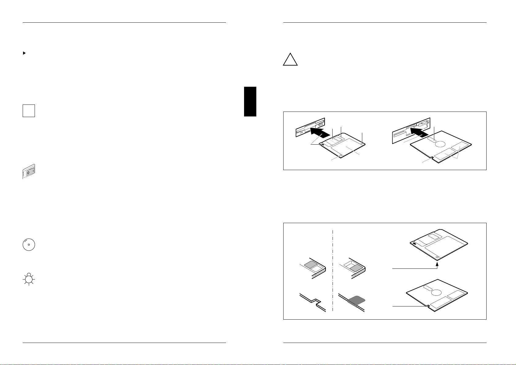
Preparing for use and operation Working with floppy disks
Working with floppy disks
!Follow the instructions supplied by the vendor of the floppy disks.
Never clean the PC's floppy disk drives with cleaning disks. Even just one
attempt would destroy the read/write head in the disk drive within 20
seconds.
There are two different floppy disk drives: The 3 1/2" floppy disk drive and the
5 1/4" floppy disk drive.
4
123
5
6
1
54
6
1 = Slot for read/write head 4 = Label area(s)
2 = Sliding metal cover 5 = Write protection indicator
3 = Hole for recognition of 3 1/2" HD disks 6 = Insertion direction
Mechanical write protection
not
write protected write protected
22 A26361-K381-Z102-2-7619

Keyboard Preparing for use and operation
The keyboard
1
3
Esc F1 F2 F3 F4 F7 F8F6F5 F9 F10 F11 F12
789
456
123
Enter
0
,
24
!
123456 890
%
Q
W E
RT U
I
O
P
7
AS
DFGHJK
L
X
C
V
B
N
M
,
.
Alt
~
`
@# $ ^
&
*
(
)
+
=
Y
Z
{
}
[
]
¦
\
:
;
"
´
<>
?
/
Caps Lock
Shift Shift
Backspace
Enter
Tab
Ctrl
Alt
Ctrl
Scroll
Lock Pause
Break
Num
Lock Scroll
Lock
Caps
Lock
Insert
Home Page
Up
Delete End Page
Down
Num
Lock
Home Pg Up
End Pg Dn
Ins Del
Prt Sc
Sys Rq
1 = Function keys 3 = Cursor control keys
2 = Alphanumeric keypad 4 = Calculator keypad (numeric keypad)
The following description of keys and key combinations refer to the MS-DOS
operating system.
Tab
Tab key
Pressing the Tab key makes the cursor jump to the next tabulator
stop.
Enter
Enter key (Return, Line feed, Carriage Return, CR)
In the operating system the Enter key is mainly used to terminate a
command line. The command entered is executed when the Enter
key is pressed.
Num
Lock Num Lock key
By pressing the Num Lock key you switch between the upper- and
lower-case levels of the calculator keypad.
At lower-case level (Num Lock lamp not lit) the cursor control
functions are active in the calculator keypad.
At upper-case level (Num Lock lamp lit) the digit and comma keys
are active.
Alt Gr
Alt Gr key (e. g. German keyboard)
To produce a character shown on the right-hand side of a key
(e. g. the character "\"on the "ß" key), hold down the Alt Gr key
and press the required key.
A26361-K381-Z102-2-7619 23
Preparing for use and operation Keyboard
Key combinations
Key combinations are generated using the Ctrl or/and Alt keys as follows:
First press and hold down the Ctrl or/and Alt key.
Then press the next key.
C
Ctrl
Aborting a current operation (Ctrl-C)
Aborts the current operation but does not delete
the keyboard buffer.
Ctrl Pause
Break
Aborting a current operation (Ctrl-Break)
Aborts a current operation instantly (depending on
the program).
Alt
Ctrl Delete
Warm boot
This key sequence resets and restarts your PC.
Details of other key combinations can be found in the User Guide of your
ioperating system and in the User Guide of the relevant application program.
Cleaning the system unit
!Turn off all power and equipment switches and pull the power plug out of
the grounded-contact utility power sockets.
Do not clean any interior parts yourself, leave this job to a service
technician.
Do not use any cleaning agents that contain abrasives or may corrode
plastic.
Ensure that no liquid enters the system.
Ensure that the ventilation areas of the system unit are free.
Wipe the system unit and monitor housing with a dry cloth, or if particularly dirty,
use a cloth which has been moistened in mild domestic detergent and then
carefully wrung out.
Use a cloth for disinfection to clean the keyboard.
24 A26361-K381-Z102-2-7619

Reinitializing the hard disk Preparing for use and operation
Reinitializing the hard disk
If the contents of the hard disk have been partially or completely deleted, you can
restore them with the system diskette and the backup diskettes. The files and
directories which existed on the hard disk when the PC was first put into use are
restored.
Restoring the entire hard disk contents
Start the PC with the system floppy disk inserted.
Partition the hard disk using the MS-DOS command FDISK (you need
knowledge of the system to do this).
Format the hard disk using the MS-DOS command FORMAT with the /s switch
(e.g. FORMAT C:/s)
Option /s causes the system files required for booting the operating system to be
copied onto the hard disk.
Create the directory DOS (z. B. MD C:\DOS ↵ ).
Copy the contents of the system diskette to directory C:\DOS on the hard disk
(e.g. XCOPY A:\*.* C:\DOS ↵ ).
Start the backup program MSBACKUP (e.g. C:\DOS\MSBACKUP ↵ ).
Restore your files on the hard disk using the RESTORE function of your backup
program and your backup disks.
Restoring individual files
Start program MSBACKUP (e.g. C:\DOS\MSBACKUP ↵ ).
Restore your files on the hard disk using the RESTORE function of your backup
program and your backup disks.
A26361-K381-Z102-2-7619 25
Preparing for use and operation Code table of standard characters
Code table of standard characters
To obtain a certain character from the following table, proceed as follows:
Hold down the Alt key.
Enter the three-digit code on the numeric keypad (calculator keypad) for the
character you want.
Codes 000 to 031 are displayed on the screen as characters, but are in fact control
characters and are therefore not listed in this table.
032 =064 =@ 096 =` 128 = Ç 160 = á 192 = 224 = α
033 =! 065 =A 097 =a 129 = ü 161 = í 193 = 225 = β
034 =" 066 =B 098 =b 130 = é 162 = ó 194 = 226 = Γ
035 =# 067 =C 099 =c 131 = â 163 = ú 195 = 227 = π
036 =$ 068 =D 100 = d 132 = ä 164 = ñ 196 = 228 = Σ
037 =% 069 =E 101 = e 133 = à 165 = Ñ 197 = 229 = σ
038 =& 070 =F 102 = f 134 = å 166 = ª 198 = 230 = µ
039 =' 071 =G 103 = g 135 = ç 167 = º 199 = 231 = τ
040 =( 072 =H 104 = h 136 = ê 168 = ¿ 200 = 232 = Φ
041 =) 073 =I 105 = i 137 = ë 169 = 201 = 233 = Ξ
042 =* 074 =J 106 = j 138 = è 170 = ¬202 = 234 = Ω
1
043 =+ 075 =K 107 = k 139 = ï 171 = / 203 = 235 = δ
2
1
044 =, 076 =L 108 = l140 = î 172 = / 204 = 236 = ∞
4
045 =– 077 =M 109 = m 141 = ì 173 = ¡ 205 = 237 = ∅
046 =. 078 =N 110 = n 142 = Ä 174 = « 206 = 238 = ∈
047 =/ 079 =O 111 = o 143 = Å 175 = » 207 = 239 = ∩
048 =0 080 =P 112 = p 144 = É 176 = 208 = 240 = ≡
049 =1 081 =Q 113 = q 145 = æ 177 = 209 = 241 = ±
050 =2 082 =R 114 = r 146 = Æ 178 = 210 = 242 = ≥
051 =3 083 =S 115 = s 147 = ô 179 = 211 = 243 = ≤
052 =4 084 =T 116 = t 148 = ö 180 = 212 = 244 = ⌠
053 =5 085 =U 117 = u 149 = ò 181 = 213 = 245 = ⌡
054 =6 086 =V 118 = v 150 = û 182 = 214 = 246 = ÷
055 =7 087 =W 119 = w 151 = ù 183 = 215 = 247 = ≈
056 =8 088 =X 120 = x 152 = ÿ 184 = 216 = 248 = °
057 =9 089 =Y 121 = y 153 = Ö 185 = 217 = 249 = ⋅
058 =: 090 =Z 122 = z 154 = Ü 186 = 218 = 250 = −
059 =; 091 =[ 123 = { 155 = ¢ 187 = 219 = 251 = √
n
060 =< 092 =\ 124 = 156 = £ 188 = 220 = 252 =
2
061 == 093 =] 125 = } 157 = ¥ 189 = 221 = 253 =
062 => 094 =ˆ 126 = ~158 = Pt 190 = 222 = 254 =
063 =? 095 =_ 127 = 159 = ƒ 191 = 223 = 255 =
26 A26361-K381-Z102-2-7619

Settings in BIOS Setup
In BIOS Setup you can set the system functions and the hardware configuration of
the PC. When the PC is delivered, the default entries are valid (see technical
manual for the system board). You can customize these settings to your
requirements in BIOS Setup.
If you want to change settings in BIOS Setup, you must:
–call BIOS Setup
– select the relevant menu
– select the field for the entry you want to change
– change the entry
– make other settings, if required
– save the settings and exit BIOS Setup
This section shows you how to call and operate BIOS Setup. The menus and setting
options provided by BIOS Setup are described in detail in the technical manual for
the system board.
Calling BIOS Setup
Reboot the PC.
One of the following messages will be displayed at the bottom of the screen:
Press <F2> to enter Setup
Press <F1> to resume, <F2> to Setup
Press function key F2 .
If you have assigned a setup password, you must now enter this password
iand confirm it with the Return key.
The Main menu of BIOS Setup is displayed on the screen.
A26361-K381-Z102-1-19 27
Settings in BIOS Setup
Phoenix BIOS Setup Copyright 1985-94 Phoenix Technologies Ltd.
Main Advanced Security Power Exit
System Time: [07:42:19]
System Date: [02/28/1995]
Diskette A: [1.4M]
Diskette B: [None]
Hard Disk 1: 540 Mbyte
Hard Disk 2: None
Hard Disk 3: None
Hard Disk 4: None
Video Display: [EGA/VGA]
Boot Options
Base Memory: 640K
Extended Memory: 15M
Item Specific Help
F1 Help ↑↓ Select Item -/+ Change Values F9 Setup Defaults
ESC Exit ←→ Select Menu Enter Execute Command F7 Previous Values
1
2
3
4
Example of Main menu of BIOS Setup
1 = Menu bar 3 = Information area
2 = Working area 4 = Operations bar
The BIOS Setup screen is divided into the following areas:
– Menu bar (1)
In the menu bar, you can select the different BIOS Setup menus.
– Working area (2)
The working area displays the setting options (fields) of the selected menus.
You can set the entries in the displayed fields according to your requirements.
indicates fields which open further submenus. You can change entries in
these submenus.
– Information area (3)
The information area displays brief information on the selected field.
– Operations bar (4)
The operations bar indicates which keys you can use to operate BIOS Setup.
You can display more information on the functions of the keys by pressing
iF1 .
28 A26361-K381-Z102-1-19

Settings in BIOS Setup
Operating BIOS Setup
If you want to exit BIOS Setup without saving the new settings:
– press the Esc key to enter the Exit menu
– select the option Discard Changes & Exit
– press the Return key
Changing settings
To select the required menu in the menu bar, use the cursor keys ←or →.
To select the required field, use the cursor keys ↑ , ↓ . The selected field is
outlined.
To display a submenu, select the corresponding field (marked with ) and press
the Return key. Press the Esc key to return from the submenu to its superior
menu.
To change the entry for the selected field, use the + or - keys on the numerical
keypad.
To set the default entries for the selected menu, press the F9 function key.
To revert the fields of the selected menu to the entries that were in effect when
BIOS Setup was called, press the F7 function key.
Saving settings
To save changed settings without exiting BIOS Setup, select Save Changes in the Exit
menu.
If you change entries in BIOS Setup, make a note of the changed entries
i(e.g. in the technical manual for the system board), or print out the changed
screen page.
You can print the current screen page using the key combination
Shift + Print if a printer is connected to the PC's parallel interface.
A26361-K381-Z102-1-19 29
Settings in BIOS Setup
Exiting BIOS Setup
To exit BIOS Setup, select the Exit menu from the menu bar. You can then decide
which settings you want to save. The Exit menu offers the following options.
You must mark the required option and activate it with the Return key.
Save Changes & Exit
This option saves the current settings in the menus and exits BIOS Setup. The PC
is rebooted and the new settings come into effect.
Discard Changes & Exit
This option discards the changes you have made. The settings which were in force
when BIOS Setup was called remain effective. BIOS Setup is terminated and the
PC is rebooted.
If you have set or changed passwords, these remain effective.
i
Get Default Values
This option reverts all the menus of BIOS Setup to the default entries. If you want
to exit BIOS Setup with these settings, select Save Changes & Exit.
Load Previous Values
This option loads the entries which were in effect when BIOS Setup was called. If
you want to exit BIOS Setup with these settings, select Save Changes & Exit.
Save Changes
This option saves settings without exiting BIOS Setup.
30 A26361-K381-Z102-1-19

Property and data protection
The following options are open to you for protecting your system and personal data
from unauthorized access:
– Preventing input with QLOCK
– Using BIOS Setup security functions
By combining these three options, you can achieve optimum protection for your
system.
Preventing input with QLOCK
The QLOCK programs disable the mouse and the keyboard for input. Under MS-
Windows, you can use the QLOCK.EXE or QLOCKWIN.EXE program; under MS-
DOS you can use the QLOCK.COM program.
For information on QLOCK.EXE and QLOCKWIN.EXE, you can call the Help menu
item if you have started the program under MS-Windows.
You will find information on QLOCK.COM under Info in MS-Windows or in the
QLOCK.TXT file on the diskette utility.
Using BIOS Setup Security functions
The Security menu in BIOS Setup offers you various options for protecting your
system and personal data from unauthorized access.
Preventing unauthorized BIOS Setup calls
You can activate this protection by setting a setup password in the Security menu.
Preventing unauthorized system access
You can activate this protection by setting a system password in the Security menu.
Preventing system boots from the diskette drive
You can activate this protection by selecting the value Diskette Lock for the System
Load: field in the Security menu.
A26361-K381-Z102-1-19 31
Property and data protection
Deactivating BIOS Setup prompt
You can suppress the "Press <F2> to enter Setup" message which is
output when the system is booted.You can activate this protection by selecting
the value Disabled for the Setup Prompt field in the Security menu.
Activating virus warnings
You can have a warning output if the boot sector has been modified. To activate
this warning, select the value Enabled for the Virus Warning field in the Security
menu.
Preventing unauthorized writing of diskettes
To activate this protection, select the value Disabled for the Diskette Write field in the
Security menu.
Protect BIOS Setup from overwriting
To activate this protection, select the value Disabled for the Flash Write field in the
Security menu.
You will find a detailed description of the Security menu in the Technical
imanual for the system board. The sections "Setting the Setup password"
and "Setting the system password" will help you assign passwords.
32 A26361-K381-Z102-1-19
Other manuals for SCENIC H
1
Table of contents
Other Siemens Nixdorf Desktop manuals


