Siemens PXC3.E16A100A User manual

CM1N9203en_05
2015
-11-23
Building Technologies
s
9203
9203mmP01
Desigo™ TRA
Room automation stations
PXC3.E...
•Modular, programmable room automation stations for HVAC, lighting, and
shading.
•BACnet / IP communications; BACnet profile ASC (BTL label).
•Optional island bus to connect TX-I/O modules with any data point mix
(including bus supply).
•Optional KNX PL-Link peripheral bus to connect sensors, actors and room
units (including bus supply).
•Optional DALI bus to connect ballasts (including bus supply).
•Optional Connection of individual devices with KNX S-Mode via
KNX PL-Link.
•Ethernet switch for communication and tool connection.
•USB Device interface.
•Operating voltage AC 24 V.
•Mounting on standard mounting rail.

2 / 12
Siemens PXC3.E... Room automation stations CM1N9203en_05
Building Technologies 2015-11-23
Use
Starting with Desigo V5, PXC3 series room automation stations with Total Room
Automation applications (TRA) can be used for buildings with more sophisticated
requirements on functionality and flexibility. TRA is used when several disciplines
(HVAC, lighting, shading) are combined to form one total solution and when total
flexibility is required. TRA is perfect for solutions optimizing energy (class A)
without loss of comfort.
Functions
A PXC3 series room automation station can assume control for multiple rooms.
These programmable room automation stations provide the infrastructure to
provide and process system- and application-specific functions.
Desigo
version
Product No.
Stock No.
Function Number of I/O
data points
KNX PL-
Link
TX-I/O modules DALI bus
V6
PXC3.E16A-
100A
S55376-C118
DALI applications
only 64 3) - - - - max. 64
ballasts 4)
PXC3.E72-100A
S55376-C130
typically 4 rooms
typically 8 room
segments
1)
140 3) max. 64
devices
max. 72 physical
I/O points - -
PXC3.E72A-
100A
S55376-C131
typically 4 rooms
typically 8 room
segments 1)
140 3) max. 64
devices
max. 72 physical
I/O points
max. 64
ballasts 4)
PXC3.E75-100A
S55376-C132
typically 8 rooms
typically 16 room
segments
1)
280 3) max. 64
devices
max. 200 physical
I/O points - -
PXC3.E75A-
100A
S55376-C133
typically 8 rooms
typically 16 room
segments 1)
280 3) max. 64
devices
max. 200 physical
I/O points
max. 64
ballasts 4)
V5.1
V5.1SP 2) PXC3.E72
S55376-C100
typically 4 rooms
typically 8 room
segments
2)
140 3) max. 64
devices
max. 72 physical
I/O points - -
PXC3.E72A
S55376-C101
typically 4 rooms
typically 8 room
segments
2)
140 3) max. 64
devices
max. 72 physical
I/O points
max. 64
ballasts 4)
PXC3.E75
S55376-C102
typically 8 rooms
typically 16 room
segments 2)
280 3) max. 64
devices
max. 200 physical
I/O points - -
PXC3.E75A
S55376-C103
typically 8 rooms
typically 16 room
segments
2)
280 3) max. 64
devices
max. 200 physical
I/O points
max. 64
ballasts 4)
1) Architectural building grid (also called room axis).
2) If V6 applications are loaded into a V5.1 device, less rooms are supported,
because V6 applications require more memory space.
To find out, DCM features the Load calculation tool.
3) Total number of data point used by TX-I/O, KNX PL-Link and DALI.
For details see Desigo Technical principles CM110664, chapter 18.
4) Commercially available DALI -ballasts with a DALI address.
Control of several
rooms
Variants

3 / 12
Siemens PXC3.E... Room automation stations CM1N9203en_05
Building Technologies 2015-11-23
•The room automation stations have a 2-port Ethernet switch to support for low-
cost cabling via line topology.
•A USB Device port is available for service and commissioning.
•TX-I/O modules connected directly to the PXC3 allow for direct connection of
field devices. This offers maximum flexibility.
•The KNX PL-Link peripheral bus supports room operator units, sensors, and
actuating devices. Selected Siemens field devices to the KNX PL-Link bus
(devices with the KNX PL-Link logo) can be connected.
The KNX PL-Link bus supports integration of commercially available devices
with KNX S-Mode (requires ETS engineering).
•The DALI bus supports lighting control. Commercially available DALI EBGs
(electronic ballasts) can be connected.
Equipment combinations
Depending on the type, PXC3 series room automation stations can be operated
with TX-I/O devices and devices with KNX PL-Link.
DALI device type
Description
Supported
0
Fluorescent Lamps
Yes
7
Switching Function
Yes
1
Self-contained Emergency Lighting
Yes **)
3
Low Voltage Halogen Lamps
Partly *)
5
Conversion digital into D.C. Voltage
Partly *)
4
Incandescent Lamps
No
2
HID Discharge Lamps
No
6
LED Modules
Yes **)
8
Colour Control
No
9
Sequencer
No
10
Optical Control
No
*) Partly supported means that basic functions are supported like with type 0, but
no further type specific functions.
**) In Desigo V6 and later
Communications
TX-I/O, KNX PL-Link
DALI

4 / 12
Siemens PXC3.E... Room automation stations CM1N9203en_05
Building Technologies 2015-11-23
Mechanical design
The compact build allows for mounting the devices on a standard mounting rail.
1
2
3
45
6
8
9
7
11
12 12
10
13
12
1
Plastic housing
2
Island bus plug connection
3
T 10 A fuse for AC 24 V peripheral supply via island bus
4
Plug-in terminal block (operating voltage)
5
Plug-in terminal block KNX PL-Link
6
2-port Ethernet switch (with 2 LEDs per port for display purposes)
7
DALI bus
8
LED display for device and system status
9
USB Device interface
10
Service pin
11
Service pin DALI
12
Slider for mounting on DIN rail
13
Island bus cover (supplied with the device)
The bus supplies for island bus, KNX PL-Link and DALI are integrated in the room
automation station.
For better reliability of the room automation station, the bus supplies and the
AC 24 V outlets are independent from the room automations station's own supply.
V6: The bus supplies are switched on by default and can be swiched off via tool if
not needed.
V5.1: The bus supplies are switched off automatically as long as no device is
connected to the respective bus during engineering.
V5.1 devices do NOT support the V6 functionality of field bus supply management.
The internal KNX PL-Link supply must not be operated in parallel with an
external supply. It must be switched off via tool when using an external supply.
This is typically the case if the devices connected to the KNX PL-Link consume
more than the 160 mA available from the internal supply.
Power supply
KNX PL-Link supply

5 / 12
Siemens PXC3.E... Room automation stations CM1N9203en_05
Building Technologies 2015-11-23
The internal bus supplies can be reinforced by external power supply modules.
An additional TXS1.12F10 supply module must be switched on and off at the same
time as the room automation station. Otherwise, DC 24 V island bus supply may
sag, resulting in alarms.
LED indicators (depending on the type)
9203z02
RUN
FLT
IB
PL
DALI
SRV
1)
2)
1) Service pin
2) Service pin DALI
9270Z05
8 7 6 5 4 3 2 1
LED
Color
Activity
Function
RUN
Green
Continuously ON
Continuously OFF
Flashing
Device ready to operate.
No supply for device.
Start-up or program halted
FLT
Red
Continuously OFF
Continuously ON
Rapid flashing
OK
HW or SW error.
Wrong or corrupted application.
IB
Yellow
Continuously ON
Flashing
Continuously OFF
OK.
Island bus communication.
No modules connected
TX-I/O modules not configured or
communication fault.
PL
Yellow
Continuously ON
Flashing
Continuously OFF
OK.
KNX PL-Link communication.
KNX PL-Link not used or communication
fault.
DALI
Yellow
Continuously ON
Flashing
Continuously OFF
OK
DALI bus communication
DALI not used or communication fault.
SVC
Red
Continuously OFF
Blinking
Blinking per wink
command*)
OK.
No application loaded.
Physical identification of the room
automation station.
Ether-
net
1 / 2
Green
Continuously ON
Continuously OFF
Flashing
Link active
Link inactive
Network activity
Yellow
Continuously ON
Continuously OFF
Link 100 Mbps
Link 10 Mbps
*) Wink command
pattern:
2s 1s
21s
5 Hz 5 Hz
9222z02
2s 1s
Service pins
Pin
Action
Description
(depending on the type) 1) Short press Ethernet Physical identification of the room automation
station in the network.
2)
Short press
DALI test: All ballasts On or Off.
Long press DALI test: Start / stop the following function:
"All ballasts blink (2 s On, 2 s Off)".
Product documentation
•Engineering and commissioning: See ABT online help.
•Installation manual Desigo TRA, CM111043.
•TX-I/O planning and installation manual, CM110562.
•Application Guide for IP Networks in Building Automation Systems, CM110668.
•Desigo Technical principles CM110664, chapters 18 and 26.
Island bus supply

6 / 12
Siemens PXC3.E... Room automation stations CM1N9203en_05
Building Technologies 2015-11-23
Engineering
•Each device has a unique serial number for commissioning support.
It is also located on the removable barcode label: See the ABT online help for
the associated workflow.
•Each device has a unique MAC address.
•Each device with KNX PL-Link has a unique KNX ID.
•Cable length, topology, etc.: See installation manual Desigo TRA, CM111043.
Caution!
•The cable insulation must always comply with the present rated voltage.
•When the supply voltage of the room automation station is transited to external
devices, the cable cross section must always correspond to the rated current
of the safety circuit breaking device.
Observe local regulations in any case.
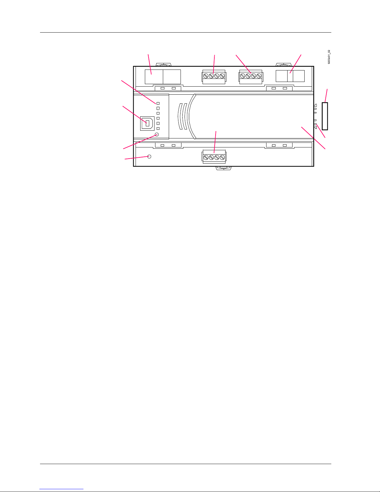
Mounting
The room automation stations can be snapped onto a standard mounting rail.
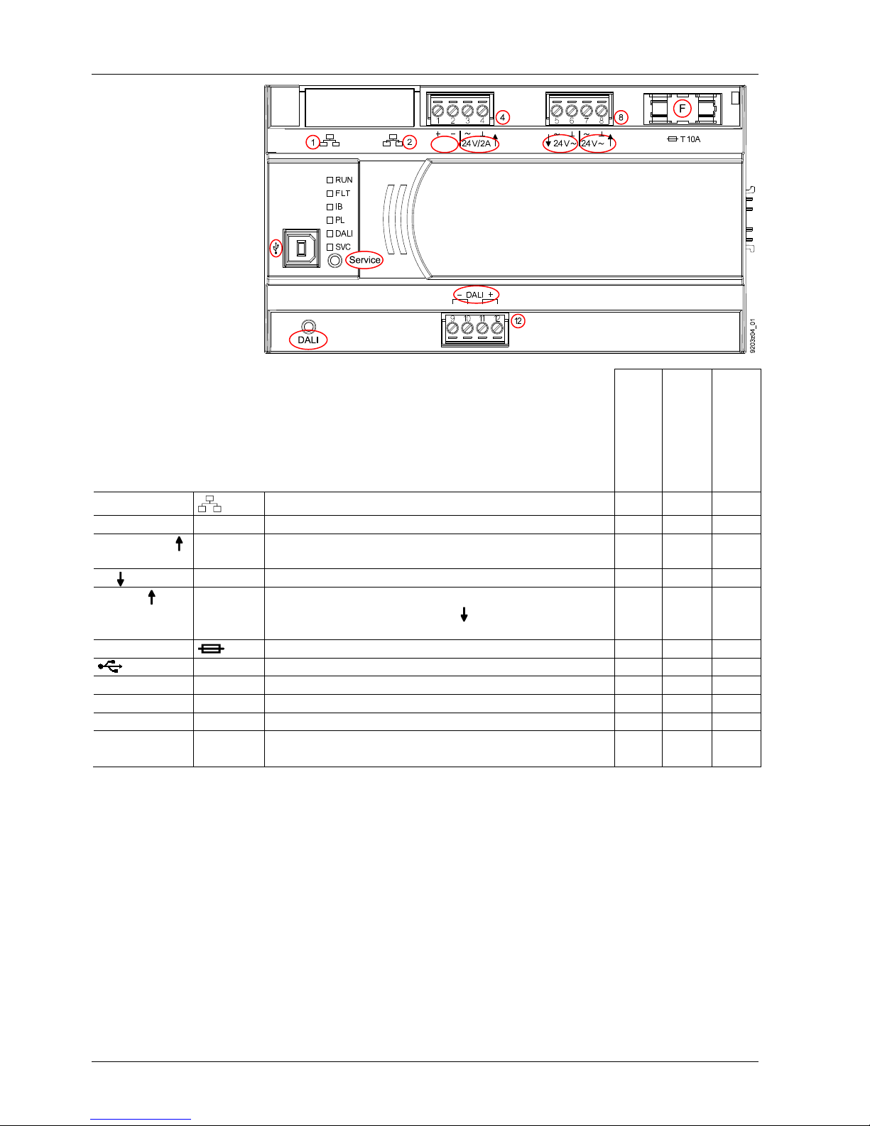
The automation station has pluggable screw terminal blocks to connect the AC 24
V supply, the AC 24 V outlets, the KNX PL-Link, and the DALI bus.
The TX-I/O modules are snapped onto the mounting rail on the right side of the
room automation station. The island bus is created automatically in this process.
Recommended
With restrictions *)
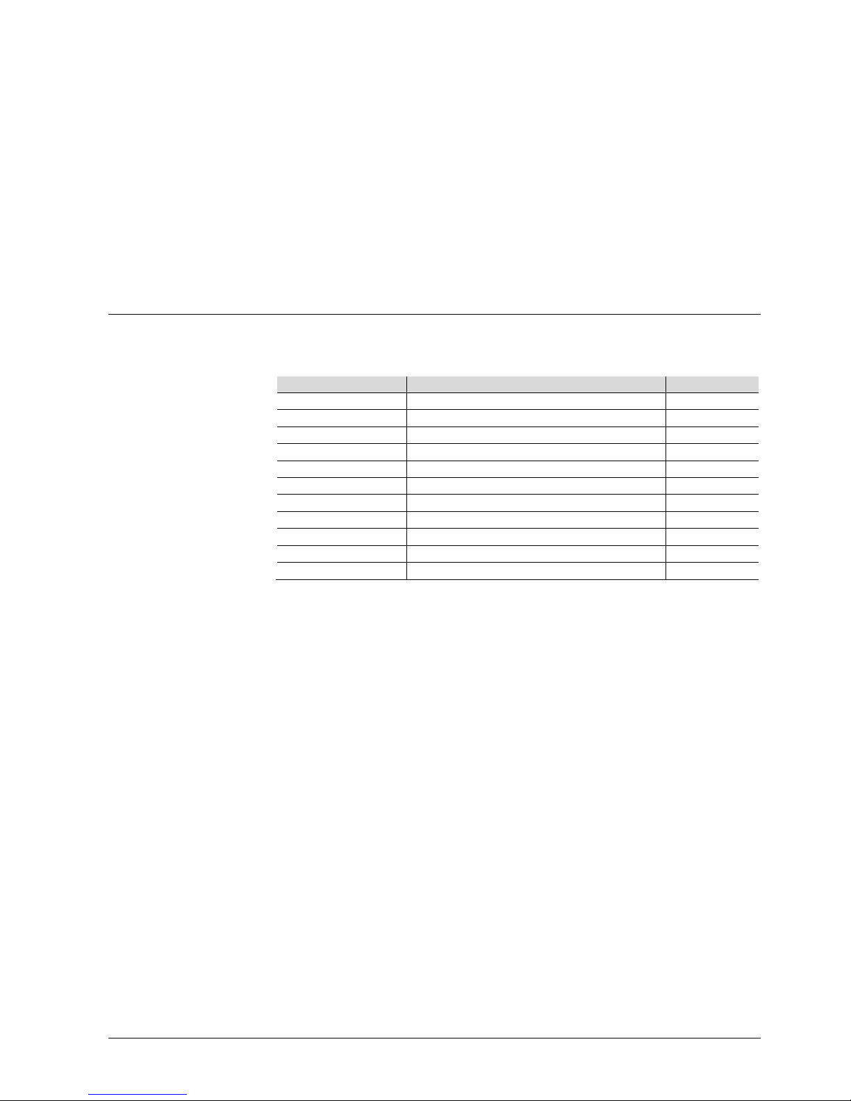
•Wall, horizontal from left to right
or from right to left
•Over head.
•On a horizontal surface.
•Wall, vertical from bottom to top
or from top to bottom.
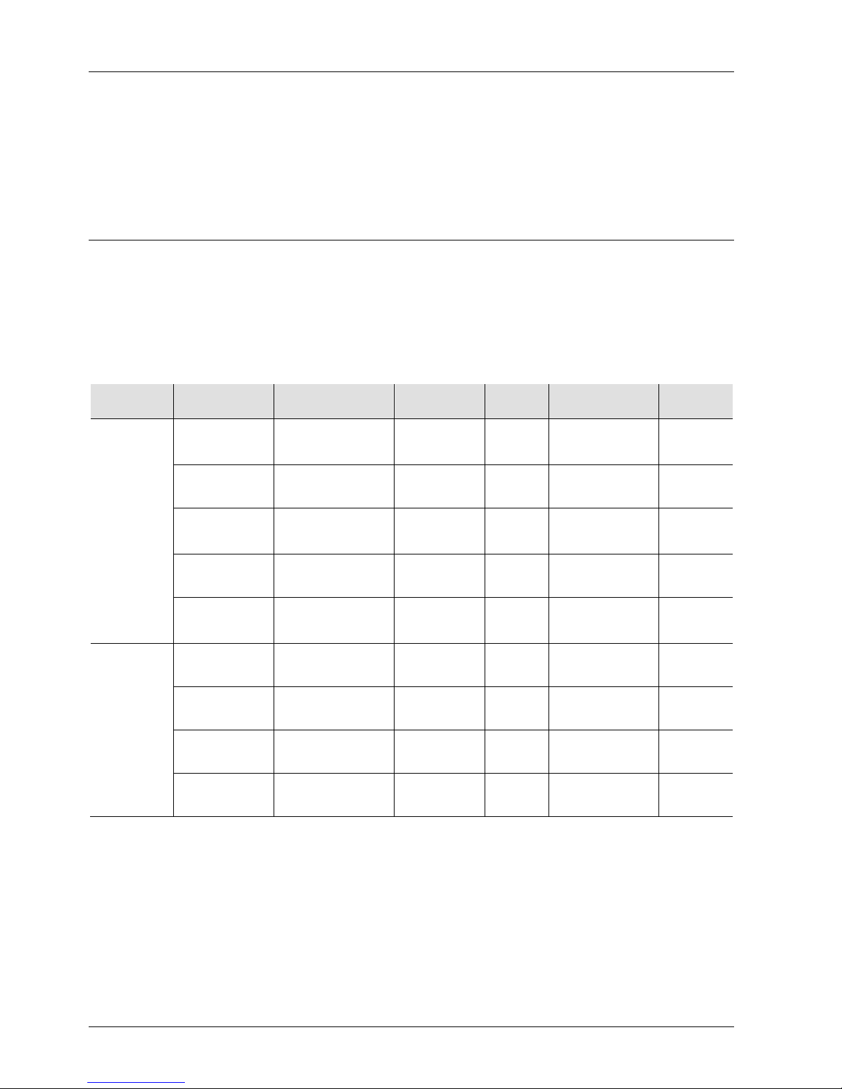
Ambient temperature -5...50 °C /
23...122 °F
Ambient temperature -5...45 °C /
23...122 °F *)
*) 50 °C / 122 °F is admissible if the bus supplies use max. 2/3 of the specified
load: KNX PL-Link 105mA, DALI 85mA and island bus 400mA.
PXC3.E16A-100A: 50 °C / 122 °F is admissible without restrictions.
You must ensure, however, that sufficient ventilation is available to maintain
the permissible ambient temperature for the devices (inside the cabinet /
installation box).
Outside, the temperature must be 10 K lower.
Installation
See installation manual Desigo TRA, CM111043.
Island bus Polarity: If a TXS1.12F10 supply module is connected to output
24 V, do not invert ~ and ⊥.
The devices are not damaged but island bus communications will not work.
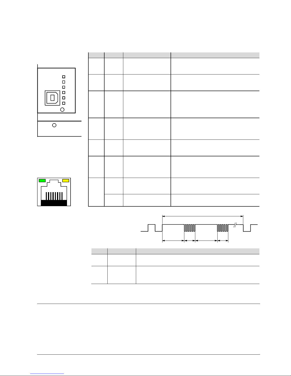
Operation
If island bus or USB communications do not work, this is an indicator that the
AC 24 V operating voltage is incorrectly wired (conductors ~ and ⏊inverted).
Mounting position
Note
STOP
Note!

7 / 12
Siemens PXC3.E... Room automation stations CM1N9203en_05
Building Technologies 2015-11-23
Technical data
Operating voltage
(24V~, ⊥)
Safety extra-low voltage SELV or
protection by extra-low voltage PELV
Half-wave load
AC 24 V -15 % / +20%
48...63 Hz
Symmetric
Operating data Processor PXC3.E...-100A (V6)
PXC3.E7... (V5.1)
Texas Instruments AM3352, 600 MHz
Atmel AT91SAM9G20, 400 MHz
Memory PXC3.E...-100A (V6)
PXC3.E7... (V5.1)
512 MB SDRAM (DDR3)
512 MB NAND Flash
128 MB SDRAM (SDR)
256 MB NAND Flash
Power consumption
Max. permissible input current
AC 24 V (through terminals 5 and 6)
Total max. 10 A
(Ext. fusing compulsory: max. T 10 A
melting fuse or max. C 10 A circuit
breaker)
Base load (without loading by modules
and field devices)
8 VA / 0.33 A
Island bus supply *)
30 VA / 1.25 A
KNX PL-Link supply *) **)
12 VA / 0.50 A
DALI supply *)
9 VA / 0.37 A
*) The bus supplies can be switched off via tool if not used.
**) The NX PL-Link supply MUST be switched off via tool if an external
bus supply is used.
Transit power AC 24 V TX-IO (island bus)
KNX PL-Link: AC 24V
(terminals 3, 4)
AC 24 V / 6 A
(terminals 7 and 8, for additional
AC 24 V consumers)
144 VA / 6 A
48 VA / 2 A
144 VA / 6 A
(only if the sum of 10 A at terminals
5 and 6 is not exceeded)
Fusing of the supply
outputs for field supply
AC 24 V /2 A (KNX PL-Link, terminals
3 and 4)
PTC resistor, short-circuit proof
Caution!
AC 24 V
(terminals 7 and 8)
No internal fusing
Island bus conductor V~
T 10A fuse (slow, exchangeable)
Response to power /
communication failure
•Energy reserve (supercap) to support real-time clock (3 days).
•Start-up time after power failure: approx. 90 s
Ethernet interface
Plug
2 x RJ45, screened
Interface type
100BaseTX, IEEE 802.3 compatible
Bit rate
10 / 100 Mbps, autosensing
Protocol
BACnet over UDP/IP
USB interface
Plug
Type B (USB device)
Data rate (USB 1.1)
12MBit/s
Galvanic isolation of ⊥
No
Protective circuit against surges and
over current
Yes (balancing currents are limited, also
in the GND conductor)

8 / 12
Siemens PXC3.E... Room automation stations CM1N9203en_05
Building Technologies 2015-11-23
Island bus interface
Communications
Interface type
Siemens specific protocol
DC output
Nominal voltage
DC 24V
Max. current 600 mA
(sufficient for typically 8 TX-I/O modules)
Parallel switchable with 3 supply
modules TXS1.12F10
For details, see: TX-I/O planning and
installation manual, CM110562)
Short-circuit proof, overload-proof
Self-resetting
Protection
Short-circuit proof
Island bus connector on
side
Protection against faulty wiring with
AC 24 V
No electric protection.
Use the terminal cover.
KNX PL-Link interface
Communications
Interface type
KNX, galvanically separated
Transceiver
TP-UART
Baud rate
9.6 kbps
Bus power supply
Nominal voltage
DC 29 V
Max. supply
Note: for devices with higher power
requirement, use the output AC 24 V
2 A, see above.
160 mA for max 32 devices with KNX
PL-Link. Default: Auto detection; must
be turned off via ABT if external bus
supply is used.
Up to 64 devices with KNX PL-Link can
be operated using one or two external
bus supplies.
Protection Short-circuit proof
Protection against miswiring up to AC 24 V
DALI interface
Communications
Interface type
DALI, galvanically separated
Baud rate
1.2 kBit/s
Insulation strength
Reinforced insulation for 230 V (1.5 kV)
Suitable for installations in overvoltage
category III (4 kV).
Bus power supply
Nominal voltage
DC 16 V
Max. current
128 mA for max 64 DALI devices
Protection
Short-circuit proof
Upon power-on, AC 230 V bus voltage is
recognized on terminals DA+ and DA–.
NO protection against miswiring with AC 24 V or AC 230 V:
Voltage between DA+ / DA+ or between DA– / DA– will destroy the DALI PCB!
Wiring, topology, cable
length, cross section
See installation manual TRA, CM111043.
Connection terminals,
plug-in
Construction type
Copper-wire or Cu-strand
with wire end sleeve
Copper-strand without
wire end sleeve
Pluggable screw terminals
1 x 0.6 mm dia. to 2.5 mm2(22 to 14 AWG)
or 2 x 0.6 mm dia. to 1,0 mm2(22 to 18 AWG)
1 x 0.6 mm dia. to 2.5 mm2(22 to 14 AWG)
or 2 x 0.6 mm∅to 1.5 mm
2
(22 to 16 AWG)
Screwdriver Slot screws
Screwdriver, size 1
Max. tightening torque
0.6 Nm (0.44 lb-ft)

9 / 12
Siemens PXC3.E... Room automation stations CM1N9203en_05
Building Technologies 2015-11-23
Assignment as per EN
60730
Operation of automatic controller
Degree of pollution
Construction type
Type 1
2
Protection class III
Housing
protection standard
Protection type as per EN 60529
Front parts in the DIN section
Terminal part
IP30
IP20
Ambient conditions
Operation
Climatic conditions
Temperature (see page 6)
Humidity
Mechanical conditions
As per IEC 60721-3-3
Class 3K5
-5 ... 50 / 45 °C (23...122/113 °F)
5…95% r.h.
Class 3M2
Transport
Climatic conditions
Temperature
Humidity
Mechanical conditions
As per IEC 60721-3-2
Class 2K3
-25...70 °C (-13 ...158 °F)
5…95% r.h.
Class 2M2
Standards, directives and
approvals
Product standard
Product family standard
General requirements for Home and
Building Electronic Systems (HBES) and
Building Automation and Control Systems
(BACS)
EN 60730-1
EN 50491-2
EN 50491-3
EN 50491-5
EU conformity (CE)
See CM1T9203xx *)
Electromagnetic compatibility (EMC)
For use in residential, commercial
and industrial environments
RCM-conformity (EMC)
See CM1T9222en_C1 *)
UL approbation
UL 916
EAC Eurasian conformity
For all PXC3.E...-100A types
Meets the requirements for eu.bac certification (excepted PXC3.E16A-100A).
See product list on: http://www.eubaccert.org/licences-by-criteria.asp
License
Application
Control accuracy [K]
212196
Fan-Coil 4-pipe Heating / Cooling
0.3 / 0.1
Environmental
compatibility
The product environmental declaration
CM1E9203 *) contains data on
environmentally compatible product design
and assessments (RoHS compliance,
materials composition, packaging,
environmental benefit, disposal)
ISO 14001 (Environment)
ISO 9001 (Quality)
*) The documents can be downloaded from http://siemens.com/bt/download.
Color
Housing
RAL 7035 (light-gray)
Dimensions
Housing as per DIN 43 880, see dimensions
Weight
PXC3.E7x....
349g / 392g
Without / with
packaging
PXC3.E7xA...
373g / 416g
PXC3.E16A...
347g / 390g
Disposal
The devices are considered electronics devices for disposal in terms of
European Directive 2012/19/EU (WEEE) and may not be disposed of as
domestic waste.
Dispose of the devices via the proper channels.
Follow all local and currently applicable laws and regulations.

10 / 12
Siemens PXC3.E... Room automation stations CM1N9203en_05
Building Technologies 2015-11-23
Connection terminals and interfaces
KNX
PXC3.E7x...
PXC3.E7xA...
PXC3.E16A-100A
1, 2
2 x RJ45 interface for Ethernet (2-port Ethernet switch) X X X
4 KNX
+, –
KNX PL-Link connection
X
X
*)
4 24 V / 2A ~, ⊥, 2 A Output AC 24 V for externally supplied devices with KNX
PL-Link (Short-circuit proof with PTC resistor)
X X *)
8 24 V~
~, ⊥
Operating voltage AC 24 V
X
X
X
8 24 V ~, ⊥, 6 A Output AC 24 V to supply other PXC3... room automation
stations (internally connected to 24 V on pcb – no
internal fusing)
X X X
F
T 10 A fuse for island bus conductor V~
X
X
*)
USB
USB interface
X
X
X
12
DALI
DALI bus connection
*)
X
X
Service
Service pin Ethernet
X
X
X
DALI
DALI test
*)
X
X
(Without
labels)
Island bus The island bus is created automatically when TX-I/O
devices are snapped on the standard mounting rail
X X *)
*) Fitted, but no labeling and no function in this type

11 / 12
Siemens PXC3.E... Room automation stations CM1N9203en_05
Building Technologies 2015-11-23
24V~
CS
5 6 7 8
V~
9203z05_01
T 10A
9 10 11 12
~
24V~
24V/2A
KNX 2)
+~~
PTC
KNX
Island bus
DALI
DALI 3)
1 2 3 4
+
Island
Bus 1)
1), 2) Not with PXC3.E16A-100A
3) Only with PXC3.E....A... types
Basic circuit diagram
(connections AC 24 V,
fusing)

12 / 12
Siemens PXC3.E... Room automation stations CM1N9203en_05
Building Technologies 2015-11-23
Dimensions
9203M01
All dimensions in mm
2012 Siemens Switzerland Ltd Subject to change
This manual suits for next models
8
Table of contents
Other Siemens Home Automation manuals
Popular Home Automation manuals by other brands

Netricity
Netricity HD Powerline 200m HomePlug user manual

Energeeks
Energeeks EG-BW003MC Quick installation guide

Firefly
Firefly VEGATOUCH Coach House V4 manual

Intesis Software
Intesis Software IntesisHome TO-RC-WIFI-1 installation guide

MyGate
MyGate PTP45 Series installation manual

Eaton
Eaton xComfort CRCA-00 Assembly instructions