Wichtiger Hinweis Die hier beschriebenen Produkte wurden entwickelt, um als Teil einer Gesamtanlage oder
Maschine sicherheitsgerichtete Funktionen zu übernehmen. Ein komplettes sicherheitsgerichtetes
System enthält in der Regel Sensoren, Auswerteeinheiten, Meldegeräte und Konzepte für sichere
Abschaltungen. Es liegt im Verantwortungsbereich des Herstellers einer Anlage oder Maschine
die korrekte Gesamtfunktion sicherzustellen. Die SIEMENS AG, ihre Niederlassungen und Beteili-
gungsgesellschaften (im Folgenden “SIEMENS”) sind nicht in der Lage, alle Eigenschaften einer
Gesamtanlage oder Maschine, die nicht durch SIEMENS konzipiert wurde, zu garantieren.
SIEMENSSIEMENS übernimmt auch keine Haftung für Empfehlungen, die durch die nachfolgende
Beschreibung gegeben bzw. impliziert werden. Aufgrund der nachfolgenden Beschreibung können
keine neuen, über die allgemeinen SIEMENS-Lieferbedingungen hinausgehenden, Garantie-,
Gewährleistungs- oder Haftungsansprüche abgeleitet werden.
Important Notice The products described herein are designed to be components of a customized machinery safety-
oriented control system. A complete safety-oriented system may include safety sensors, evalua-
tors, actuators and signaling components. It is the responsibility of each company to conduct its
own evalution of the effectiveness of the safety system by trained individuals. SIEMENS AG, its
subsidiaries and affiliates (collectively "SIEMENS") are not in a position to evaluate all of the
characteristics of a given machine or product not designed by SIEMENS.
SIEMENS accepts no liability for any recommendation that may be implied or stated herein. The
warranty contained in the contract of sale by SIEMENS is the sole warranty of SIEMENS. Any
statements contained herein do not create new warranties or modify existing ones.
Montagevorschlag Zweihandbedienpult mit Safety at Work
Suggested assembly of two-hand operation console with Safety at Work
Montage-
folge /
Assembly
order
Bildliche Darstellung
Visual display
Beschreibung Montage
Description of assembly
Erforderliche Teile
Required components
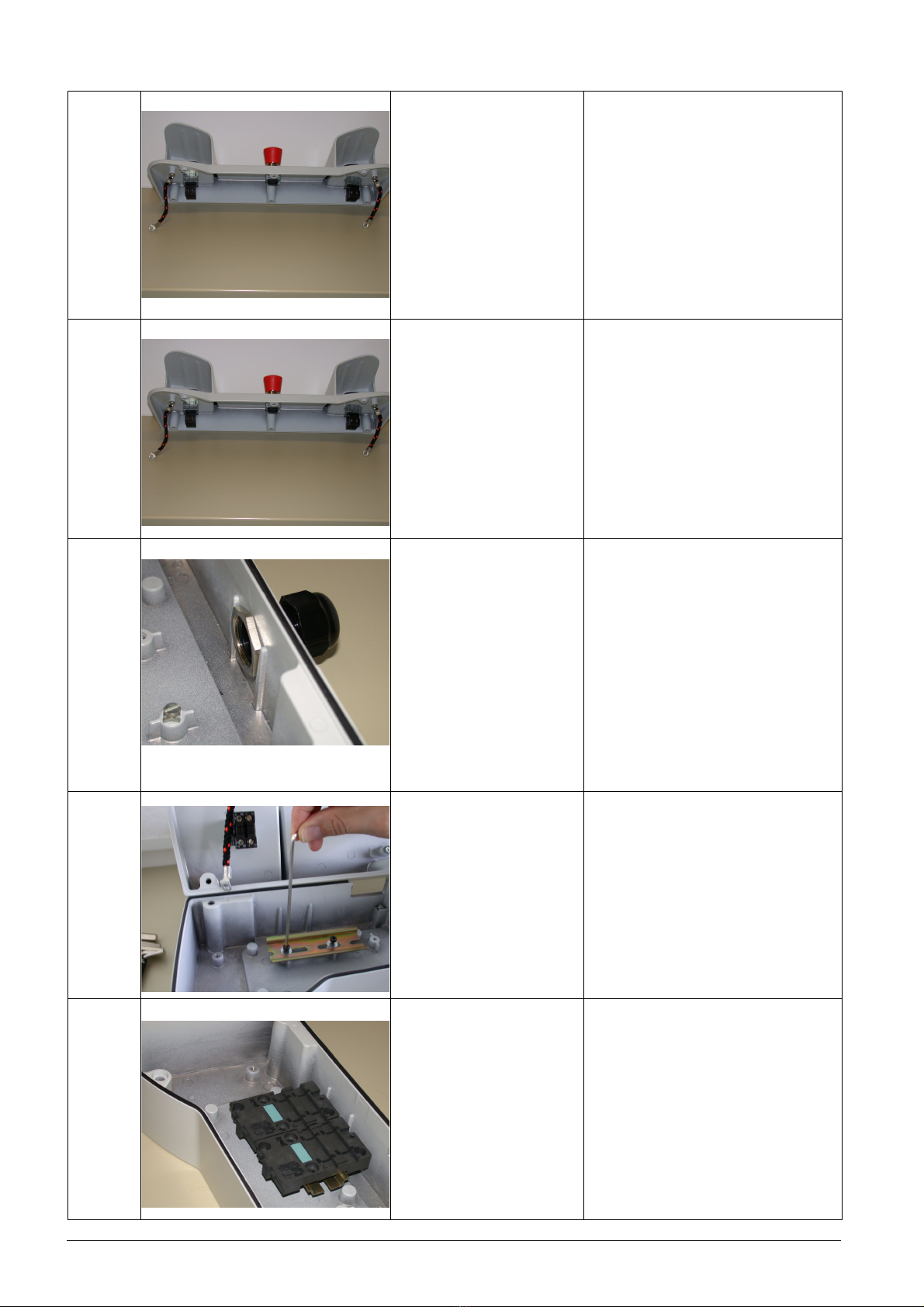
1
Öffnung für die
Kabeldurchführung ausbrechen
Break out opening for cable
gland
1 Stück Zweihandbedienpult
3SB38 63-4BC
alternativ: 1 Stück 3SB38 63-4BB
bei dieser Type entfallen die
Montageschritte 2 und 3
1 unit two-hand operation console
3SB38 63-4BC
alternatively: 1 unit 3SB38 63-4BB
steps 2 and 3 are not required for
this type
Zweihandbedienpult 3SF...
AS-Interface F
Two-hand operation console
AS-Interface F
Betriebsanleitung/Operating Instructions
SAFETY AT WORK
GWA 4NEB 370 0110-12a 1
WARNUNG WARNING
Gefährliche elektrische Spannung!
Kann zu elektrischem Schlag
und Verbrennungen führen.
Vor Beginn der Arbeiten Anlage
und Gerät spannungsfrei schalten.
HAZARDOUS VOLTAGE.
Can cause electrical shock
and burns.
Disconnect power before proceeding
with any work on this equipment.
! !
Vor der Installation, dem Betrieb oder der Wartung des Geräts muss diese Anleitung gelesen und verstanden werden.
Read and understand these instructions before installing, operating, or maintaining the equipment.