Siemens ALCC User manual

SiemensSiemens
SiemensSiemens
Siemens IndustryIndustry
IndustryIndustry
Industry,,
,,
,Inc.Inc.
Inc.Inc.
Inc.
BuildingBuilding
BuildingBuilding
Building
TT
TT
Tecec
ecec
echnologies Dihnologies Di
hnologies Dihnologies Di
hnologies Divisionvision
visionvision
vision
P/N 315-050263-3
Audio Level Conversion Card
Installation Instructions
ModelALCC
INTRODUCTION The Model ALCC from Siemens Industry, Inc., is an
Audio Level Conversion Card that contains two audio
channels. Each channel is capable of accepting speaker-
level audio at 70VRMS from Siemens amplifier models
ZAC-30 (MXL) and ZAC-40 (XLS/Desigo Fire Safety
Modular/Cerberus PRO Modular).There is a single
output channel of line-level audio for connection to the
AIC (Audio Input Card).
The ALCC adds system-wide live emergency paging
capability to networked XLS/Desigo Fire Safety
Modular/Cerberus PRO Modular Voice systems as well
as an all-call function for XLS/Desigo Fire Safety
Modular/Cerberus PRO Modular-based MXL/XLS/
Desigo Fire Safety Modular/Cerberus PRO Modular
hybrid systems. Located on the receiving end in up to
63 remote XLS/Desigo Fire Safety Modular/Cerberus
PRO Modular nodes, the ALCC converts the audio
signal generated by the amplifiers located in the
primary and secondary paging stations into a form that
is compatible with AICs located in the remote stations.
The ALCC is transparent to the host system. As such, it
supports all styles of wiring supported by ZAC-40 (XLS/
Desigo Fire Safety Modular/Cerberus PRO Modular) as
well as ZAC-30 (MXL) amplifiers. It provides supervision
by constantly monitoring its two audio channels,
reporting faults both visually and through the down-
stream AIC. Furthermore, the ALCC contains audio
detection and channel selection circuitry that prioritizes
incoming audio, enables the appropriate channel,
closes the AIC audio active contact, or cuts the output
of the ALCC to generate an AIC trouble, depending on
the presence of incoming audio or circuit faults. Finally,
all XLS/Desigo Fire Safety Modular/Cerberus PRO
Modular functions are configured in the Zeus program-
ming tool via standard logic functions with no need for
special software or hardware upgrades.
• Two isolated audio channels, 70VRMS input from ZAC-30 (MXL) or ZAC-40
(XLS/Desigo Fire Safety Modular/Cerberus PRO Modular) amplifiers.
• Single channel output to the AIC, 0.775VRMS.
• ±6dBu output adjustment capability, independent for each channel.
• Up to 63 ALCCs on a single audio riser.
PRIMARY SELECTED
SECNDRY SELECTED
POWER
ALCC
FAULT TEST
GAIN
_
+
ACTIVE
FAULT
SECONDARY
CHANNEL
FAULT TEST
GAIN
ACTIVE
FAULT
PRIMARY
CHANNEL
_
+
Figure 1
ALCC Speaker Line
Output Card
Features

Siemens Industry, Inc.
Building Technologies Division
P/N 315-050263-32
• Visually indicated input channel prioritization control logic based on audio
activity and fault detection.
• Audio path supervision for both channels, reported visually by LEDs and to
the system by the AIC audio input supervision circuitry.
• All-analog circuitry makes the ALCC completely transparent to the overlying
system structure.
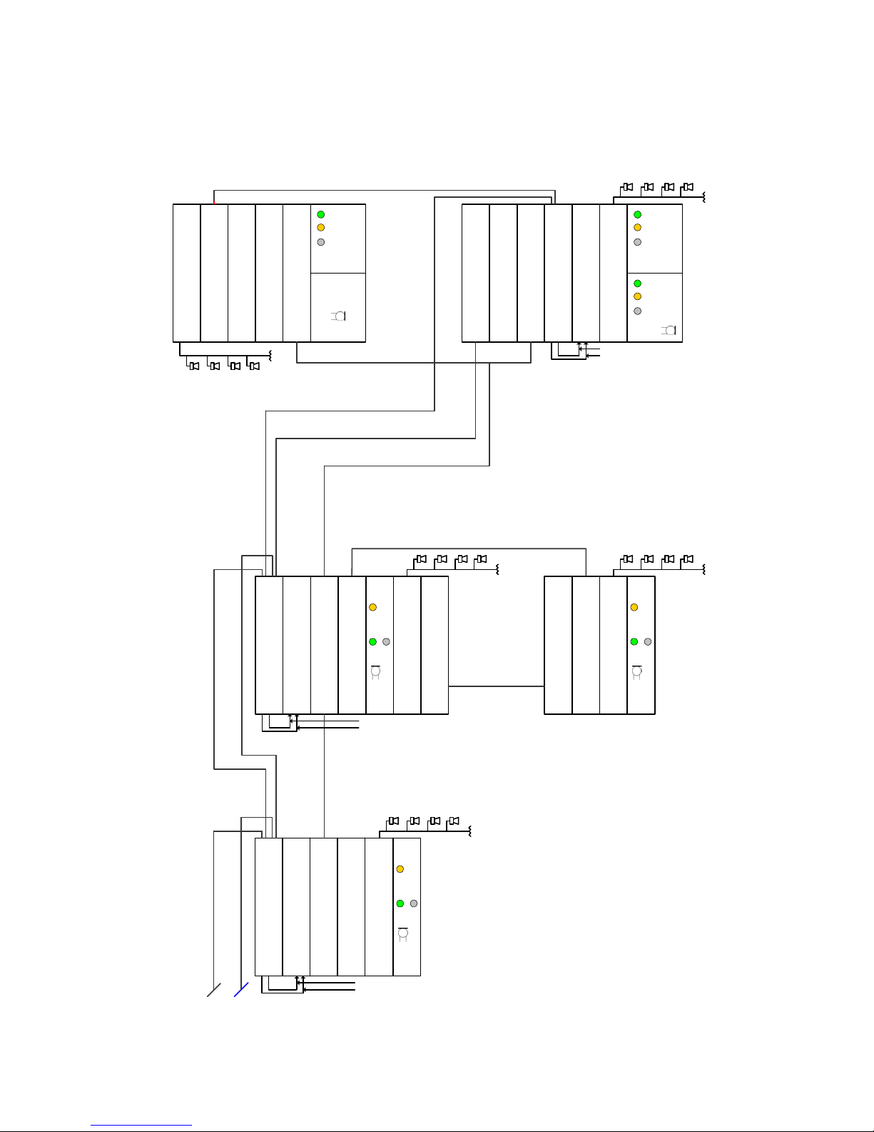
OPERATION The ALCC provides the capability of conducting a global emergency page across
multiple remote XLS/Desigo Fire Safety Modular/Cerberus PRO Modular nodes, up to
63 nodes per audio riser. The emergency page originates at an XLS/Desigo Fire
Safety Modular/Cerberus PRO Modular or MXL global paging station, where it is
broadcast at 70VRMS over an audio riser by a ZAC-40 (XLS/Desigo Fire Safety
Modular/Cerberus PRO Modular) or ZAC-30 (MXL) amplifier. A single remote XLS/
Desigo Fire Safety Modular/Cerberus PRO Modular node contains one ALCC, which
steps the incoming speaker-level audio down to line-level audio that is compatible
with the AIC audio input (0.775VMRS, independently adjustable to ±6dBu). The AIC
digitizes the audio, which is subsequently transmitted by a DAC-NET to local
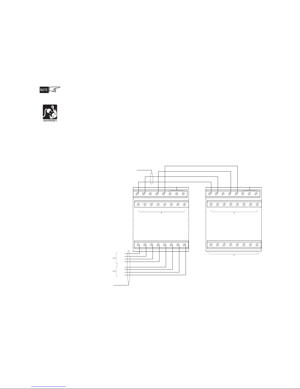
amplifier(s) for broadcast over the local speaker zones.The ALCC incorporates two
independent audio channels and is therefore capable of supporting two global paging
stations. In case of a simultaneous page, the ALCC control logic prioritizes the
primary channel over the secondary channel. On-board audio detection circuitry
monitors the audio risers for incoming audio, while supervision circuitry reports any
issues with the audio path via front-accessible LEDs, and, if necessary, disconnects
its output from the AIC input, causing a trouble to be reported to the system. The
ALCC relies on the originating amplifier for supervision of the audio risers, and on the
AIC for supervision of the connection to the ALCC. Since the AIC monitors the
presence of signal on its audio input, it is responsible for reporting audio path faults
to the XLS/Desigo Fire Safety Modular/Cerberus PRO Modular system.
The ALCC contains no digital circuitry and integrates seamlessly into the existing
XLS/Desigo Fire Safety Modular/Cerberus PRO Modular framework, as it is com-
pletely transparent to the overlying system structure.
Refer to the ALCC Usage Restrictions on page 8.
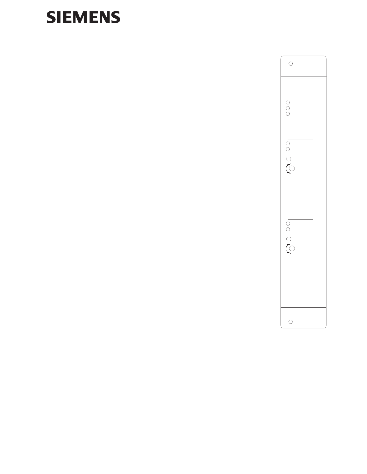
Controls and Indicators The following table contains a description of LED indicators visible through the front
bezel of the ALCC:
DELROLOCETATS"NO"ROFSETON ETATS"FFO"ROFSETON
REWOPneerG.derewopsiCCLAehTekaM.derewoptonsiCCLAehT fI.ylreporpn
ideggulpsidracerus ,21-CSPnoeruliafrofkcehc,os 2-CC/5-CC
YRAMIRP EVITCA neerGehtnooiduafoecneserpsetacidnI .
resiryramirp ehtnooiduafoecnesbasetacidnI figniriwresirkcehC.resiryramirp .detcepxesioidua
YRADNOCES EVITC
AneerGehtnooiduafoecneserpsetacidnI .resiryradnoces ehtnooiduafoecnesbasetacidnI figniriwresirkcehC.resiryradnoces .detcepxesioidua
YRAMIRP DETCELES neerGdecruossiCCLAehtfotuptuoehT .resiryramirpehtmorf decruossiC
CLAehtfotuptuoehT .resiryradnocesehtmorf
YRADNOCES DETCELES neerGdecruossiCCLAehtfotuptuoehT .resiryradnocesehtmorf decruossiCCLAehtfotuptuoehT .resiryramirpehtmorf
YRAMIRP TLUAF wolleYyramirpehtnotneserpsitluafA eh
tgnilcycyrT.lennahcoidua .dracehtotrewop
yllufsilennahcoiduayramirpehT .lanoitcnuf
YRADNOCES TLUAF wolleYyra
dnocesehtnotneserpsitluafA ehtgnilcycyrT.lennahcoidua .dracehtotrewop
yllufsilennahcoiduayradnocesehT .la
noitcnuf

Siemens Industry, Inc.
Building Technologies Division
P/N 315-050263-33
The following table contains a description of controls accessible through the front
bezel of the ALCC:
EMANEPYTNOITPIRCSED
NIAG1LENNAHC TNEMTSUJDA retemoitnetoP yramirpCCLAehtfotuptuoehtstsujdA .uBd6+dnauBd6-nee
wteblennahc
NIAG2LENNAHC TNEMTSUJDA retemoitnetoP yradnocesCCLAehtfotuptuoehtstsujdA .uBd6+dnauBd6-neewteb
lennahc
1LENNAHC TSETTLUAF hctiwSyratnemoM .tsettluaflennahcyramirpCCLA .ylnoesuyrotcaF
2LENNAHC TSETTLUAF hc
tiwSyratnemoM .tsettluaflennahcyradnocesCCLA .ylnoesuyrotcaF
Figure 2
Installing The ALCC
WIRING
Remove all system power before installation, first battery then AC. (To power up,
connect the AC first, then the battery.)
All field wiring of the ALCC is connected to the CC-2/CC-5 terminal blocks located
above and below the card cage slot, in which it is installed.
To connect external wiring:
1. Loosen the screw of the terminal by turning it counterclockwise.
2. Insert the wire into the side of the terminal block.
3. Tighten the screw of the terminal block by turning it clockwise.
For all versions of Zeus earlier than 7.0, the ALCC is not
an option under CC-5 or CC-2. As a result, such proper-
ties as card cage slot availability and battery / power
supply current draw must be accounted for manually
in those Zeus versions prior to 7.0.
It is recommended to install the ALCC in a slot adjacent
to the AIC.
INSTALLATION The ALCC plugs perpendicularly into a CC-2 or CC-5 slot via two 96-pin DIN connec-
tors and can occupy any slot in the card cage.
Slide the ALCC card into the card guides front bezel up, until the card edge connec-
tors contact the motherboard receptacles. The LEDs, test buttons, adjustment
potentiometers, and the legend should be visible and accessible.
Verify that the card edge connectors align properly with
the motherboard receptacles.There is only one correct
way to plug in the card. If it does not align, DO NOT
FORCE the card.
Place thumbs on the front panel adjacent to the captive
screws and gently apply even pressure on the card
until the connectors plug firmly into the motherboard
receptacles. Secure the ALCC to the card cage with
captive screws.
Power up the system and verify that the ALCC power
LED turns ON.

Siemens Industry, Inc.
Building Technologies Division
P/N 315-050263-34
Figure 3 is an example system diagram of an XLSV/Desigo Fire Safety Modular/
Cerberus PRO Modular network with both MXL (primary) and XLSV/Desigo Fire
Safety Modular/Cerberus PRO Modular (secondary) global paging stations.
Figure 3
ALCC Example System Wiring
ZAC-30
PRIMARY GLOBAL PAGING STATION SECONDARY GLOBAL PAGING STATION
ALCC
AUDIO
AUDIO PRESENT CONTACT
EOLR
XLSV/Desigo Fire
Safety Modular
Cerberus PRO
Modular
XLSV/Desigo Fire
Safety Modular/
Cerberus PRO
Modular
OCC-1
XNET
XNET
AUDIO PRESENT CONTACT
AUDIO
AIC
NIC-C
ZAC-40 or ZAM-180
LED
switch
LED
VSM-1
LED
switch
LED
ACM-1
(not required for
global paging from
an MXLV head end )
XNET
ZAC-40
DAC-NET
NIC-C
SCM-8
ALCC
LVM
ALCC
NIC-C
DAC-NET
AIC
AUDIO
AUDIO PRESENT
AIC
CONTACT
XLSV/Desigo Fir
e
Safety Modular/
Cerberus PRO
Modular
MXLV
XLSVR/Desigo Fire
Safety Modular/
Cerberus PRO
Modular
NIC-C
ZAC-40 or ZAM-180
LED
switch
LED
LVMMMM-1
NIM-1W
NIC-C
DAC-NET
HNET HNET
LED LED
switch
DAC-NET
DNET
LED LED
switch
LED LED
switch
SECONDARY AUDIO RISER
PRIMARY AUDIO RISER
SECONDARY AUDIO RISER
PRIMARY AUDIO RISER
SECONDARY AUDIO RISER
PRIMARY AUDIO RISER
REMOTE PAGING STATION WITH EXTERNAL CABINET
EOLR EOLR
ZAC-40 or ZAM-180
EOLR
EOLR
ZAC-30 or EL-410D
ZAC-40 or ZAM-180
REMOTE PAGING STATION
XNET
PRIMARY AUDIO RISER
(local page only)
LVM
(local page only)
LVM
(local page only)

Siemens Industry, Inc.
Building Technologies Division
P/N 315-050263-35
Figure 4 illustrates redundant audio riser wiring for global paging applications that use
the ALCC.
PRIMARY GLOBAL
PAGING STATION SECONDARY GLOBAL
PAGING STATION
XLSV/Desigo
Fire Safety
Modular/
Cerberus
PRO
Modular
PRIMARY AUDIO RISER #1
ZAC-40
ZAC-40
ZAC-40
ZAC-40
PRIMARY AUDIO RISER #2
SECONDARY AUDIO RISER #1
SECONDARY AUDIO RISER #2
ALCC
ALCC
AIC
SECONDARY RISER AUDIO
SECONDARY PRESENT CONTAC
T
PRIMARY RISER AUDIO
PRIMARY PRESENT CONTACT
REMOTE PAGING STATION
XLSV/Desigo
Fire Safety
Modular/
Cerberus
PRO
Modular
XLSV/Desigo
Fire Safety
Modular/
Cerberus
PRO
Modular
Figure 4
ALCC Redundant Audio Riser Diagram

Siemens Industry, Inc.
Building Technologies Division
P/N 315-050263-36
12345678
12345678
910111213141516
910111213141516
17 18 19 20 21 22 23 24
17 18 19 20 21 22 23 24
DO NOT USE
DO NOT USE
+IN
PRIMARY AUDIO RISER
+IN
+OUT
+OUT
-OUT
-OUT
-IN
-IN
AUDIO IN
DO NOT USE
ONE SLOT OF CC-2 / CC-5
AIC
ALCC
AUDIO ACTIVE DRY CONTACT -
AUDIO ACTIVE DRY CONTACT +
AUDIO OUT -
AUDIO OUT +
DO NOT USEDO NOT USE
SECONDARY AUDIO RISER
POWER LIMITED
POWER LIMITED
Figure 5
ALCC Wiring
NOTES
ALCC terminals 1, 2, 4, and 5:
1. Install the ALCC and the AIC
in adjacent slots of a CC-5 /
CC-2.
2. Audio connection on
terminals 1 and 2 is
supervised; the dry contact
connection on terminals 4
and 5 is not supervised.
3. 18AWG min., 12AWG max.
unshielded twisted pair
(UTP).
4. Audio connection on
terminals 1 and 2 is rated for
maximum (+15dBu
(4.34VRMS) into 600
Ohms).
ALCC terminals 17 – 24:
1. Supervised and power
limited.
2. 18AWG min., 12AWG max.
Use shielded or unshielded
twisted pair (STP or UTP).
3. If using shielded cabling,
terminate shields at one end
only.
4. 80 ohms max. per riser,
70VRMS, 40W max.,
supervised, power limited.
5. Line capacitance is 0.33 μF
Line to Line, 0.66 μF Line to
Ground max. for each audio
riser.
6. Parallel wiring (T-tapping) is
not allowed.
7. All ALCC audio riser wiring
is rated power limited and
should be wired in
accordance with applicable
codes.
8. The ALCC supports both
Class A and Class B audio
riser wiring. Refer to Figure
6 for details.
Figure 5 outlines the input and output connections of the ALCC and the relevant
input connections of a nearby AIC. Please refer to AIC Installation Instructions, P/N
315-035300, for details on AIC wiring.
In order to ensure correct wiring of the audio riser, please follow the installation
instructions for the respective originating amplifiers being used in the global paging
stations. All amplifier specifications, such as the style and class of wiring or the
values of EOL resistors, remain in effect. Please note that the ALCC has been
designed exclusively for use with one of the following amplifiers: ZAC-40 (XLS/
Desigo Fire Safety Modular/Cerberus PRO Modular) or ZAC-30 (MXL).
Make sure the amplifiers’ outputs are set to 70VRMS. Please refer to the ZAC-40
Installation Instructions, P/N 315-035400, or the ZAC-30 Installation Instructions, P/N
315-092960, as appropriate.
Do not adjust the volume on the AIC. Use the ALCC volume adjustment potentiom-
eter to adjust volume for each channel independently.

Siemens Industry, Inc.
Building Technologies Division
P/N 315-050263-37
Figure 6
ALCC Class A and Class B Wiring Diagram
GLOBAL PAGING
STATION
CLASS A
EOLR
68k OHMS
ZAC-40
(XLS/Desigo
Fire Safety
Modular/
Cerberus PRO
Modular)
or
ZAC-30
(MXL)
CLASS B
EOLR
68k OHMS
CLASS A ONLY
AUDIO RISER (CLASS A and CLASS B)
LAST
ALCC FIRST
ALCC

Siemens Industry, Inc.
Building Technologies Division
Florham Park, NJ
Siemens Canada, Ltd.
1577 North Service Road East
Oakville, Ontario
L6H 0H6 Canada
P/N 315-050263-3
ELECTRICAL RATINGS
REWOPTUPNI
tnerruCenalPkcaBV42Am531
tnerruCV42lanimreTwercS0
tnerruCenalPkcaBV2.6Am01
tnerruCybdnatSV42Am59
The back plane and screw terminal currents represent the absolute maximum
currents that are consumed by the ALCC in the worst case operating condition.
These currents are used only for power supply loading calculations.The standby
current represents the current consumed from the 24V battery by the ALCC in the
quiescent standby mode.This current is used in the battery size calculation.
USAGE RESTRICTIONS For UL and ULC approved product the following usage restrictions apply:
a. The ALCC cannot be used with the Fireman’s Master Telephone (FMT) or
the Telephone Zone Card (TZC-8B) as the source of paging audio.
For UL approved product the following usage restrictions apply:
a. The maximum power of the ZAM-180 amplifier using the ZAC-40 (XLS/
Desigo Fire Safety Modular/Cerberus PRO Modular) as the ALCC paging
source is limited at 170W.
b. The maximum power of the ZAM-180 amplifier using the ZAC-30 (MXL) as
the ALCC paging source is limited at 160W.
For ULC approved product the following usage restrictions apply:
a. The maximum power of the ZAM-180 amplifier using the ZAC-40 (XLS/
Desigo Fire Safety Modular/Cerberus PRO Modular) as the ALCC paging
source is limited at 165W.
b. The ZAC-30 (MXL) is not allowed as the ALCC paging source.
Document ID A6V10248630
Cyber security disclaimer
Siemens products and solutions provide security functions to ensure the secure operation of building comfort,
fire safety, security management and physical security systems. The security functions on these products and
solutions are important components of a comprehensive security concept.
It is, however, necessary to implement and maintain a comprehensive, state-of-the-art security concept that is
customized to individual security needs. Such a security concept may result in additional site-specific preventive
action to ensure that the building comfort, fire safety, security management or physical security system for your
site are operated in a secure manner. These measures may include, but are not limited to, separating networks,
physically protecting system components, user awareness programs, defense in depth, etc.
For additional information on building technology security and our offerings, contact your Siemens sales or
project department. We strongly recommend customers to follow our security advisories, which provide infor-
mation on the latest security threats, patches and other mitigation measures.
http://www.siemens.com/cert/en/cert-security-advisories.htm
Table of contents
Other Siemens Sound Card manuals