Siemens ASC-2 User manual

P/N 315-092085-11
Installation Instructions
Model ASC-2
Audio Supervision Card
INTRODUCTION
The Model ASC-2 Audio Supervision Card
from Siemens Industry, Inc. supervises the
output of one primary amplifier and one
backup amplifier in an MXLV System. The
ASC-2 compares the amplifier output to the
amplifier input from the OMM-1. If they do not
match, a trouble indicates on the MKB-2. The
supervised output may be connected in Style
Y or Style Z. The audio output can be con-
nected to the ZC zone card series.
If the primary amplifier fails, the ASC-2
switches:
• the input signal for the failed amplifier to
the backup amplifier,
• and the backup amplifier output to the
audio channel formerly served by the
failed amplifier.
This card provides the means for multiple
ASC-1/-2 cards that supervise many amplifi-
ers to share one backup amplifier.
The primary amplifier gets its input from the
OMM-1 terminal block adjacent to the OCC-1
Output Control Card module. The amplifiers
can be assigned to any one of the three audio
risers by setting switch S2 on the ASC-2.
Follow the switch setting instructions in the
INSTALLATION section to set the desired
amplifier input selections.
The ASC-2 occupies one of eleven sub-
addresses of the OCC-1. When installing an
ASC-2 card, use the CSG-M configuration
printout to locate the address of the card. Use
switch S1 to set a unique address for the
ASC-2 card as described in the INSTALLA-
TION section.
For additional information on the Voice
System, refer to the MXLV Manual P/N
315-092036.
Figure 1
ASC-2 Module Board
Siemens Industry, Inc.
Building Technologies Division
Florham Park, NJ
Siemens Building Technologies, Ltd.
Fire Safety & Security Products
2 Kenview Boulevard
Brampton, Ontario
L6T 5E4 Canada

2
INSTALLATION
Remove all system power before installation, first battery and then AC.
(To power up, connect the AC first and then the battery.)
1. Remove the card from its protective bag. Do
not touch the gold edge of the board.
2. Refer to the CSG-M configuration printout for
the address of the module.
3. Set the card address on switch S1 using
dipswitches SW1 - SW4.
a. Refer to Figure 2 for the location of S1.
b. Refer to Table 1 for switch settings.
c. Set the card address (See NOTE below).
NOTE: To open a dipswitch, press down on
the side of the dipswitch marked OPEN.
To close a dipswitch, press down on the
side of the dipswitch opposite the side
marked OPEN.
To open a slide switch, push the slide
to the side opposite the side marked
ON. To close a slide switch, push the
slide to the side marked ON.
X = SWITCH CLOSED OR ON, O = SWITCH OPEN OR OFF
TABLE 1
ADDR 4321ADDR 4321
ILLEGAL O O O O8XOOO
1OOOX9XOOX
2OOXO10 X O X O
3OOXX11 X O X X
4OXOOILLEGAL X X O O
5OXOXILLEGAL X X O X
6OXXOILLEGAL X X X O
7 O X X X ILLEGAL XXXX
Figure 2
Locating Switches S1 and S2 and Jumpers J1 and J2 on the ASC-2

3
Figure 3
Placing the User Key in the OMM-1
Figure 4
Location of the
User Key for the
ASC-2
b. To set the ASC-2 for 70.7V RMS:
• Refer to No. 10 below.
•
Place the J1 jumper in the right-hand po-
sition with the gold-plated edge facing up.
• Check that fuse F1 is 2A.
c. If the backup amplifier is an EL-410C/D,
place the jumper J2 in the upper position
with the gold-plated edge facing up.
This
connects the backup amplifier input
negative side to the MXLV power supply.
Otherwise, place J2 in the lower position.
Check the data sheet of your amplifier for
more information.
6. Do NOT install the card in its edge connector
until ALL OMM-1 field wiring is completed
and checked for shorts, opens, and other
faults. Refer to the Wiring Checkout Chart.
Replace the card in its protective bag if the
wiring is not complete.
7. Place the user key from the installation kit in
the OMM-1 card edge connector for the
ASC-2. This prevents the installation of any
other card type in the ASC-2 slot. Two keys
to prevent reverse installation of the card are
already factory installed in the OMM-1 edge
connectors. See Figures 3 and 4.
4. Set switch S2 for proper supervision of the
ASC-2.
CAUTION: Incorrect settings can cause
failure of the backup amplifier to transfer.
SETTING SWITCH S2
Amplifier input
Riser 1 Riser 2 Riser 3 ILLEGAL
SW1 O X O X
SW2 O O X X
SW3 NOT USED
SW4 NOT USED
SW5 X = Enable backup amplifier supervision
O = Disable backup amplifier supervision
X = Closed or ON, O = Open or OFF
a. Check the system wiring plan to be certain
of amplifier and riser assignments; then
set switch S2, dipswitches SW1 and SW2
by following the table above. Refer to
Figure 2 for the location of switch S2.
b. Close SW5 on switch S2 if this ASC-2 card
supervises the backup amplifier. If one
backup amplifier is shared by more than
one ASC-2 card, open SW5 of S2 on all
ASC-2 cards except the one that
supervises the backup amplifier.
5. Refer to Figure 2 again; note the position of
J1 and J2.
a. To set the ASC-2 for 25.2V RMS:
• Refer to No. 10 below.
• Place J1 jumper in the left-hand position
with the gold-plated edge facing up.
• Check that fuse F1 is 6A.

4
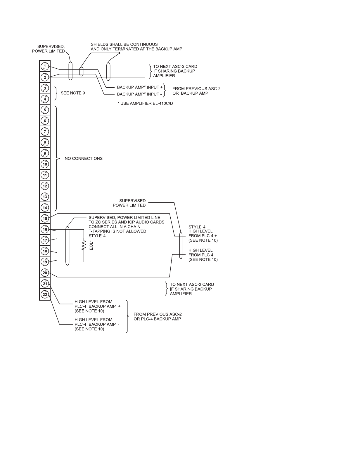
8. If one backup amplifier is shared by more
than one ASC-2, connect terminal 3 of the
terminal block on the primary ASC-2 to
terminal 3 of the terminal blocks of all other
ASC-2 cards that share the same backup
amplifier.
If the system has NO backup amplifier,
place a jumper across terminals 3 and 4.
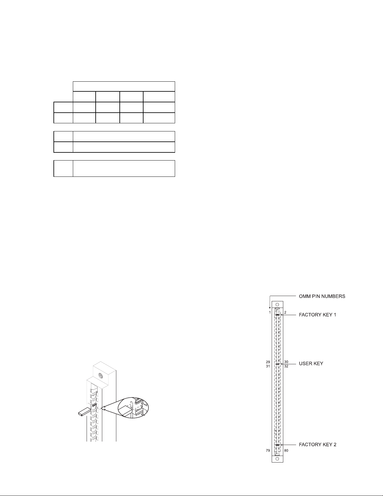
9. After completing and checking all field wiring,
place the card in its card edge connector.
The components on the board must face the
22-position terminal block where the wiring
terminates. Press the card firmly in place to
be sure it is seated properly in the edge
connector.
CAUTION
At all times handle all plug-in cards with
extreme care. When inserting or removing
a card, be sure the position of the card is
kept at right angles to the OMM-1 board.
Otherwise, the plug-in card can damage or
displace other components.
10. If power limiting is required with a 70.7V
application, use a PLC-4. Refer to the PLC-4
Installation Instructions, P/N 315-093312, and
to Figures 5 and 6 for wiring information.
ELECTRICAL CHARACTERISTICS
tnerruCeludoMCDV5evitcAAm01
tnerruCeludoMCDV42evitcAAm08
tnerruCeludoMCDV42ybdnatSAm58
Maximum wire size: 14 AWG twisted pair,
unshielded
Minimum wire size: 18 AWG twisted pair,
unshielded
NOTE: Use unshielded twisted pair for high
level amplifier connections. Use
shielded twisted pair for terminals 1
and 2. Use single conductor wire for
other connections.
Maximum wire length:
Refer to the decibel (dB) loss chart in the
Speaker Application Guide. The wire length
includes:
(1) from the amplifier to the ASC-2,
(2) from the ASC-2 to the ZC series of
audio cards, and
(3) also includes the wire in the longest
audio zone served by the amplifier.
High level outputs: 25.2V RMS, 4.0A, 100W max
70.7V RMS, 1.4A, 100W max
Backup amplifier input: 1V RMS max
WIRING
Refer to Figures 5 and 6.
All wiring must comply with
national and local codes.
Some signal is lost in the zone wires due to line
resistance. Refer to the Speaker Application Guide
(http://www.buildingtechnologies.usa.siemens.com/
Support/?languagecode=en. Then click on Applica-
tion Guide in Fire Safety) for further information. A
reduction in load reduces the loss. Use the
largest wire size possible for minimum loss.

5
ASC-2 WIRING CHECKOUT CHART
RESISTANCE BETWEEN
TERMINALS
RESISTANCE
DESIRED
POSSIBLE CAUSE
OF PROBLEM
1 to 2 > 1 Meg Line open;
other than EL-410C/D
connected
1 through 22 to chassis > 1 Meg Short in wiring
15 to 16
17 to 18
19 to 20
> 1 Meg Line shorted
16 to 17
18 to 19
< 1.5 ohms Line open
15 to 20 0.2 ohms*
(25.2V system)
1.4 ohms*
(70.7V system)
Line open
Line open
*These are the output impedances of
the EL-410C/D power amplifier.
> = greater than, < = less than.

6
Figure 5
ASC-2 Style Y Wiring Diagram
*EOL is located at the last ZC Series or ICP audio card
NOTES:
1. All wiring must be in
accordance with Article 760 of
NEC or the local building
codes.
2. Minimum wire size: 18 AWG
twisted pair.
3. Maximum wire size: 14 AWG
twisted pair.
4. High level amplifier
connections = unshielded
twisted pair.
Low level amplifier connections
= shielded twisted pair.
Other connections = single
conductor wire
5. Maximum rating:
25.2V RMS: 100W - 4.0A each
input/output
70.7V RMS: 100W - 1.4A each
input/output
6. Maximum loop length: Refer to
Tables 2 and 3.
7. The wire length includes: The
length of the wire from the
ASC-2 to the amplifier, the
length of the wire from the
ASC-2 to the ZC Series of
audio cards and back, and the
length of the longest speaker
zone served by the amplifier.
8. End of Line device: 24K, ½W,
5%, (P/N 140-820405)
9. If there is no backup amplifier,
connect terminals 3 and 4
together. If one backup
amplifier is shared by more
than one ASC-2, connect all
terminal 3s together and leave
the terminal 4s unconnected.
10. Required for power limited
wiring.
Refer to Wiring Specification for
MXL, MXL-IQ and MXLV
Systems, P/N 315-091772
revision 6 or higher, for
additional wiring information.

7
Figure 6
ASC-2 Style Z Wiring Diagram
NOTES:
1. All wiring must be in
accordance with Article 760 of
NEC or the local building
codes.
2. Minimum wire size: 18 AWG
twisted pair.
3. Maximum wire size: 14 AWG
twisted pair.
4. High level amplifier
connections = unshielded
twisted pair.
Low level amplifier connections
= shielded twisted pair.
Other connections = single
conductor wire
5. Maximum rating:
25.2V RMS: 10W - 4.0A each
input/output
70.7V RMS: 100W - 1.4A each
input/output
6. Maximum loop length: Refer to
Tables 2 and 3.
7. The wire length includes: The
length of the wire from the
ASC-2 to the amplifier, the
length of the wire from the
ASC-2 to the ZC Series of
audio cards and back, and the
length of the longest speaker
zone served by the amplifier.
8. End of Line device: 24K, ½W,
5%, (P/N 140-820405)
9. If there is no backup amplifier,
connect terminals 3 and 4
together. If one backup
amplifier is shared by more
than one ASC-2, connect all
terminal 3s together and leave
the terminal 4s unconnected.
10. Required for power limited
wiring.
STYLE 7
Refer to Wiring Specification for
MXL, MXL-IQ and MXLV
Systems, P/N 315-091772
revision 6 or higher, for
additional wiring information.

P/N 315-092085-11
Siemens Industry, Inc.
Building Technologies Division
Florham Park, NJ
Siemens Building Technologies, Ltd.
Fire Safety & Security Products
2 Kenview Boulevard
Brampton, Ontario
L6T 5E4 Canada
Table of contents
Other Siemens Sound Card manuals
Popular Sound Card manuals by other brands

Konig
Konig CMP-SOUNDCAR21 manual

ReActiveMicro
ReActiveMicro PHASOR owner's manual

Golding Audio
Golding Audio DMS3000 Connection and General information

Phoenix Sound Systems
Phoenix Sound Systems PHOENIX BIG SOUND Special instructions for installation and use

Digigram
Digigram PCX924HR user manual

midiplus
midiplus STUDIO M user manual