manuals.online logo
Brands
  1. Home
  2. •
  3. Brands
  4. •
  5. Siemens
  6. •
  7. Thermostat
  8. •
  9. Siemens RDS120-B Owner's manual

Siemens RDS120-B Owner's manual

A6V11727385
Smart Infrastructure
06/20/2019
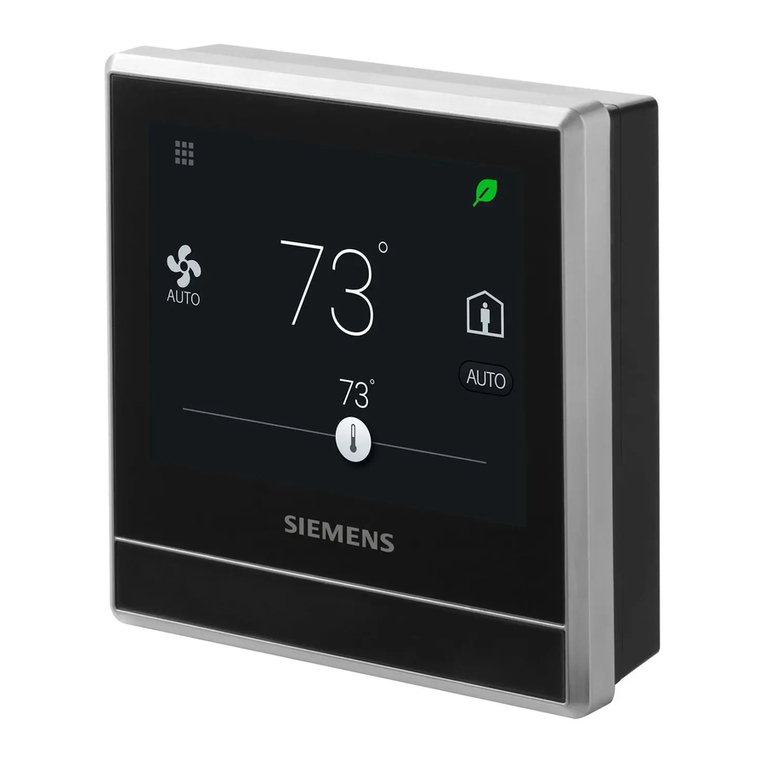
Smart Thermostat
RDS120-B Technical Instructions
Advanced cloud connected thermostat for light commercial and residential
applications
•BACnet over IP Certified
•Controls conventional HVAC systems up to 3H/2C and heat pumps up to 4H/2C
•Easy to read, backlit, auto-dimming 3.5” color LCD touch
•Intuitive remote user control using Apple iOS and Android mobile phone
applications
•One-touch green leaf button to maximize energy efficiency
•Built-in Volatile Organic Compounds (VOC) sensor enables ventilation strategies
for optimum indoor air quality
•Built-in humidity sensor
•Built-in occupancy sensor and window / door contact enables smart occupancy
control
•Full, easy to program user schedule
2
Siemens Industry, Inc.
A6V11727385
Smart Infrastructure
06/20/2019
Thermostat Highlights
●Built-in VOC sensor senses wide range of offending organic odors that contribute to stale
air and drives ventilation control
●Easy to understand tri-level air quality indication: “Good”, “Okay”, “Poor”
●Built-in temperature and humidity sensors
●Inputs for remote or averaging temperature and humidity sensors
●One-touch operation for “Away”, “OFF”, “FAN” and “Heating/Cooling”
●Configurable setpoint limits
●Password protected screen lock
●Presence detection using a built-in sensor
●PID algorithm for precise control
●Advanced energy saving control with free cooling capability
●Two multifunctional inputs, optional and configurable for:
–Room temperature
–Operating mode switch
–Window / door contact
–Outside air temperature
–Room air humidity
–Presence detector
–Condensation monitor
–Room air quality
●Six relay outputs for:
–Conventional systems up to 3H/2C
–Heat pumps with up to 2 compressors and 2 stages of auxiliary heat
–Humidity or ventilation control
●Guided Setup Wizard
●Over the air (OTA) firmware upgradable
●Green Leaf button engages occupants in maximizing system efficiency. If scheduled
setpoint is overridden, the green leaf will turn red. One touch will return the system to the
programmed setpoint and the leaf will return to green.
Mobile App Features
●Support iOS and Android smartphones
●Support “Dark” and “Light” background colors on mobile app
●Full 7-day programmable schedule with three modes:
–“Comfort”: comfort settings during occupied periods
–“Economy”: setting for transition between “Unoccupied” and “Comfort”
–“Unoccupied”: setting for periods during absence to maximize energy savings
●Duplicates thermostat HMI on smartphone screen
●User account management
●Monitor temperature and humidity
●Monitor indoor air quality: “Good”, “Okay”, “Poor”
●Data security with Siemens Cloud Computing Platform
Application
The RDS120 is designed to control Heat Pump or Conventional HVAC heating and cooling
applications. It can control up to three stages of heating and two stages of cooling in
conventional systems and up to two compressors and two stages of auxiliary heat in heat
pump systems.
3
Siemens Industry, Inc.
A6V11727385
Smart Infrastructure
06/20/2019
Mechanical Design
The room thermostat consists of the following parts:
●Front housing with touch screen and sensors
●Back housing with terminals and relays
●Mounting hardware for installation on 2’’×4’’ electrical box or directly on drywall
Operation and Settings
Active Display
1
System setup screens and detailed information display
2
Shows if the system is working in an energy-optimized mode. If the leaf is red, some
predefined settings have been changed. One touch to the leaf returns settings to
configured settings and reverts leaf color to green.
3
Room temperature
4
Manually select between “At home” and “Away”
5
Shows if the thermostat is operating per the schedule ( ) or manually ( ). Please
note:
●If there is Cloud connection and the scheduler has been programmed, the
thermostat will follow it. Any temporary change of the temperature setpoint is
effective only during the currently scheduled mode.
●If there is Cloud connection, but the schedule has not been programmed, the
thermostat follows the default schedule.
●If there is no Cloud connection, the thermostat will have no schedule and will be
operated manually.
6
Fan mode (AUTO/ON)
7
Temperature setpoint slider. Icon color changes as setpoint is changed:
●Slider changes to red when heating relay is energized.
●Slider changes to blue when cooling relay is energized.
●If system has reached setpoint and is idle, the slider color stays white.
4
Siemens Industry, Inc.
A6V11727385
Smart Infrastructure
06/20/2019
Idle Display
1
Relative humidity
2
Shows room air quality:
●Green = Very Good
●Orange = Fair
●Red = Poor
3
Shows if the system is working in an energy-optimized mode. If the leaf is red, some
pre-defined settings have been changed. One touch to the leaf returns settings to
configured settings and reverts leaf color to green.
4
Room temperature
NOTE: Idle mode display will vary based on system configuration.
Ordering Information
Model Number
Orderable Part Number
Description
RDS120-B
RDS120-B
Room Thermostat
Contents
Items
Quantity
Thermostat (front and rear)
1
Metal mounting plates (small & large)
2
Plastic frame
1
Set of screws and drywall anchors
1
Quick guide
1
Mounting instructions
1
Wiring decals
1
Activation code decal
1
5
Siemens Industry, Inc.
A6V11727385
Smart Infrastructure
06/20/2019
Associated Equipment
Remote sensors
Sensor Type
Model Number
1k
Ohm at
32°F Ni
R
1k
Ohm
Pt
RTD
Type 2
Thermistor
0-10 Vdc
Datasheet*
Room Temperature Sensors
- Wall-mount
QAA2220.EWSN
x
149-714
QAA2212.EWSN
x
149-714
QAA2230.EWSN
x
149-714
QAA22SS.EWSN
x
149-714
- Flush-
mount1)
540-984 (Metal)
x
149-956
536-994A (Beige)
x
149-956
536-994B (White)
x
149-956
- Duct-mount
QAM2030.010 (4”)
x
149-915
Outdoor Temperature Sensors
QAC22
x
149-920
QAC2012
x
149-920
QAC2030
x
149-920
QAC3161
x
149-920
Cable Temperature Sensors
QAP22
x
149-918
QAP2012.150
x
149-918
QAP1030.200
x
149-918
Room Humidity Sensors
- Wall-mount
including
temperature
QFA3212.EWSN
x(T)
x (r.h.)
149-714
QFA32SS.EWSN
x (T+r.h.)
149-714
- Duct-mount
including
temperature
QFM2160U
x (T+r.h.)
149-991
Indoor Air Quality Sensors
- CO2
QPA2000
x
149-910
- VOC + CO2
QPA2002
x
149-910
QPA2002D1)
x
149-910
- CO2
including
temperature
QPA2060
x(CO2+T)
149-910
QPA2060D1)
x(CO2+T)
149-910
- Duct-mount
CO2
QPM2100
x
149-909
- Duct-mount
VOC + CO2
QPM2102
x
149-909
- Duct-mount
CO2including
temperature
QPM2160
x(CO2+T)
149-909
6
Siemens Industry, Inc.
A6V11727385
Smart Infrastructure
06/20/2019
* The documents can be downloaded from Siemens US Download Center by specifying the
product number as shown in the above table.
1) With digital display
Replacement Part
Description
Model
Number
Orderable
Part Number
Plastic trim plate and metal mounting
plate for 2’’ × 4’’ box (1 set)
ARG100.01
S55772-T102
Product Documentation
Topic
Title
Document
number
Mounting and installation
Installation guide
A6V11727380
Installation and operation
User guide
A6V11727414
Startup wizard
Quick guide
A6V11727429
Commissioning
Commissioning guide
A6V11727391
Submittal sheet
A6V11727426
CE declaration
A5W90002476
RCM declaration
A5W90002477
Product environmental declaration
A5W90003412
Notes
Security
CAUTION
National safety regulations
Failure to comply with applicable safety regulations may result in personal injury and
property damage
●Observe and comply with the appropriate safety regulations.
Engineering
See Product Documentation [➙6] for information on engineering, selection and sizing
connecting cables for supply voltage and field devices.
7
Siemens Industry, Inc.
A6V11727385
Smart Infrastructure
06/20/2019
Installation Location
●The devices are suitable for wall installation.
●Recommended height: 5 feet above the floor.
●Do not install the devices in recesses, shelves, behind curtains or doors, or above or
near heat sources.
●Avoid direct exposure to sun and drafts.
●Seal the conduit or backwall as drafts can affect sensor readings.
●Observe maximum ambient conditions.
Wiring
Use only class 2 rated power source with proper current limiting.
Installation
Thermostat may be mounted directly on wall using drywall anchors and screws (included).
For installation on a 2” × 4” conduit box , use the appropriate mounting plate and plastic trim
piece (included).
WARNING
No user serviceable parts inside.
Risk of fire and injury due to short-circuits
●Use properly sized wires for connections
Commissioning
Refer to the Quick guide and User guide (see Product Documentation [➙6]) to configure
your device. Commissioning includes the following:
●Internet connection
●Application setup
●Account registration and device pairing
NOTE: Before configuring your thermostat, make sure you have Internet connection, a valid
email address, and a smartphone.
Operation
Operating System
8
Siemens Industry, Inc.
A6V11727385
Smart Infrastructure
06/20/2019
OS
OS version
App Store
iOS
iOS 10 or above
App store®
Android
AndroidTM 5.0 or above
Google PlayTM
Maintenance
The thermostat is designed for maintenance-free operation.
Disposal
The device is considered an electronic device for disposal in accordance
with the European Guidelines and may not be disposed of as domestic
garbage.
●Dispose of the device through channels provided for this purpose.
●Comply with all local and currently applicable laws and regulations.
Regulatory information
Radio equipment directive
The equipment is using harmonized frequency in Europe, and also compliances with the
Radio Equipment Directive (2014/53/EU, formerly 1999/5/EC).
ISED Regulations (Canada)
This device complies with Industry Canada license-exempt RSS standard(s).
Operation is subject to the following two conditions: (1) this device may not cause
interference, and (2) this device must accept any interference, including interference that
may cause undesired operation of the device.
Le present appareil est conforme aux CNR d'Industrie Canada applicables aux appareils
radio exempts de licence. L'exploitation est autorisee aux deux conditions suivantes : (1)
l'appareil ne doit pas produire de brouillage, et (2) l'utilisateur de l'appareil doit accepter tout
brouillage radioelectrique subi, meme si le brouillage est susceptible d'en compromettre le
fonctionnement.
9
Siemens Industry, Inc.
A6V11727385
Smart Infrastructure
06/20/2019
FCC Regulations (USA)
WARNING
Modification of this device to receive cellular radio telephone service signals is
prohibited under FCC rules and federal law.
This equipment has been tested and found to comply with the limits for a Class B digital
device, pursuant to part 15 of the FCC Rules. These limits are designed to provide
reasonable protection against harmful interference in a residential installation. This
equipment generates, uses and can radiate radio frequency energy and, if not installed and
used in accordance with the instructions, may cause harmful interference to radio
communications. However, there is no guarantee that interference will not occur in a
particular installation. If this equipment does cause harmful interference to radio or
television reception, which can be determined by turning the equipment off and on, the user
is encouraged to try to correct the interference by one or more of the following measures:
Reorient or relocate the receiving antenna.
Increase the separation between the equipment and receiver.
Connect the equipment into an outlet on a circuit different from that to which the receiver is
connected. Consult the dealer or an experienced radio/TV technician for help.
This equipment complies with FCC radiation exposure limits set forth for an uncontrolled
environment. This equipment should be installed and operated with minimum distance of
20cm between the radiator & your body.
Changes or modifications not expressly approved by the party responsible for compliance
could void the user's authority to operate the equipment.
Statement
This device complies with part 15 of the FCC Rules. Operation is subject to the following two
conditions: (1) This device may not cause harmful interference, and (2) this device must
accept any interference received, including interference that may cause undesired operation.
10
Siemens Industry, Inc.
A6V11727385
Smart Infrastructure
06/20/2019
Technical data
Power Supply
Power Supply
Operating voltage
24 Vac (±20%)
Frequency
48 to 63 Hz
Power consumption
Max. 9 VA
Max. power supply current
4 A current limited
Radio Data
Radio Parameter
Frequency band
2.4 to 2.4835 GHz
Maximum radio-frequency power
18 dBm
WLAN standard
IEEE 802.11b/g/n (HT20)
WLAN channel
1-11
Inputs
Connections to Multifunctional Inputs X1 - M - X2
Passive temperature sensors
- Cable length max. (copper
cable
section)
- NTC type
Room temperature range
Outdoor temperature range
- Ni type
Room temperature range
Outdoor temperature range
- Pt type
Room temperature range
Outdoor temperature range
300 ft (90 m) (16 AWG wire), 230 ft (70 m) (18 AWG
wire)
200 ft (60 m) (18 AWGwire), 130 ft (40 m) (20 AWG
wire)
NTC10K Type 2 Thermistor
32 to 122°F (0…50°C)
-32 to 176°F (-50…80°C)
Ni1000 at 32°F (0℃) RTD
32 to 122°F (0…50°C)
-32 to 176°F (-50…80°C)
Pt1000_375/Pt1000_385 at 32°F (0℃) RTD
32 to 122°F (0…50°C)
-32 to 176°F (-50…80°C)
Active DC 0 V to 10 V sensors
- Room temperature range
(default)
- Outdoor temperature range
(default)
- Humidity range (default)
- CO2range (default)
Note: min./max. configurable via parameters
32 to 122°F (0…50°C)
-32 to 176°F (-50…80°C)
0 to 100%
0 to 2000 ppm
Digital contacts
- Operating action
- Contact sensing
Selectable N.O./N.C.
DC 14 to 40 V, 8 mA (typical)
11
Siemens Industry, Inc.
A6V11727385
Smart Infrastructure
06/20/2019
Connections to Multifunctional Inputs X1 - M - X2
- Parallel connection
- Input function
Max. 20 thermostats per switch
Selectable
Outputs
Relay Contact Capacity
Voltage
24 Vac (±20%)
Current
Min. 0.02 A, Max. 1A per output
Operational Data
Setpoint Range
45 to 95°F (7…35°C)
Built-in Room Temperature Sensor
Temperature range
Accuracy at 77°F (25°C)
Display resolution
32 to 122°F
±0.9 °F or 0.5°C
1 °F (0.5°C)
Built-in Room Humidity Sensor
Humidity range
Accuracy at 77°F (25°C)
Display resolution
0% to 100%
± 5% r.h.
1%
System Compatibility
Conventional
2 stages cooling, 3 stages heating
Heat pump
2 stages cooling and 2 stages heating (+2
stages auxiliary heating)
Connections
Interfaces
Micro USB
A service port is provided for firmware
upgrade and on-site diagnosis
Wiring Connections
Screw terminals
Solid wires or prepared stranded wires:
Max. 1 × 16 to 20 AWG
12
Siemens Industry, Inc.
A6V11727385
Smart Infrastructure
06/20/2019
PIR Sensor
Sensor Detection Range
A: The width of each cell, 80 cm (31 in).
B: The thermostat.
C: The height of each cell, 80 cm (31 in).
D: The area that the PIR sensor can detect.
Conformity
Ambient Conditions and Protection Classification
Safety class according to EN60730
Class III
Degree of protection of housing as per EN
60529
IP30 (NEMA 1)
Classification as per EN 60730
Function of automatic control devices
Type 1
Degree of contamination
2
Overvoltage category
III
Climatic ambient conditions
Storage as per EN 60721-3-1
Class 1K3
Temperature -13 to 149°F (-25 to 65°C)
Humidity 5 to 95%
Transport (packaged for transport) as per
EN 60721-3-2
Class 2K3
Temperature -13 to 149°F (-25 to 65°C)
Humidity 5 to 95%
Operation as per EN 60721-3-3
Class 3K5
Temperature 23 to 122°F (-5 to 50°C)
Humidity 5 to 95%
Mechanical ambient conditions
Storage as per EN 60721-3-1
Class 1M2
Transport as per EN 60721-3-2
Class 2M2
Operation as per EN 60721-3-3
Class 3M2
Standards, Directives and Approvals
EU conformity (CE)
A5W90002476*)
RCM conformity
A5W90002477*)
13
Siemens Industry, Inc.
A6V11727385
Smart Infrastructure
06/20/2019
Standards, Directives and Approvals
FCC standards
FCC CFR 47 Part 15 Subpart C
IC standards
RSS-247 issue 1 May 2015, RSS-GEN issue 4 November
2014
UL
UL916
BTL
BACnet Testing Laboratory
Environmental compatibility
The product environmental declaration A5W90003412*)
contains data on environmentally compatible product design
and assessments (RoHS compliance, materials composition,
packaging, environmental benefit, disposal).
*) The documents can be downloaded from http://siemens.com/bt/download.
General Data
General
Dimension
H 3.58” × W 3.58” × D 1.02”
Weight
Thermostat with package, user document and accessory
15.3 oz (435 g)
Thermostat
9.5 oz (268 g)
Color
Silver plating
Housing: Pantone black
Diagrams
Connection Terminals
Terminal
Use
RH
24 Vac, heating system
RC
24 Vac, cooling system
C
24 Vac, common
W1/O/B
Stage 1 heating (W1) in conventional system or reversing valve O/B in heat
pump system
W2/AUX
Stage 2 heating in conventional system, Stage 1 Aux Heat in heat pump
system
W3/UNIV
Stage 3 heating or universal output in conventional system, or Stage 2
auxiliary heat or universal output in heat pump system
Y1, Y2
Stages 1 and 2 cooling in conventional system or Stages 1 and 2
compressor in heat pump system
G
Fan
X1, X2
Configurable input
M
Common for X1/X2 inputs
14
Siemens Industry, Inc.
A6V11727385
Smart Infrastructure
06/20/2019
Wiring Diagrams
Jumper in Place
Jumper Removed
NOTE:
●For US installations use Class 2 rated power source. For other installations, use current
protection with current rated at max. 4A.
●If a single transformer is used, keep jumper RH-RC in place. Connect 24 Vac to the RC
terminal, and neutral to terminal C. If separate transformers are used for heating and
cooling systems, remove jumper RH-RC. Connect cooling 24 Vac to terminal RC,
neutral to terminal C and heating 24 Vac to terminal RH.
15
Siemens Industry, Inc.
A6V11727385
Smart Infrastructure
06/20/2019
Dimensions
16
Siemens Industry, Inc.
A6V11727385
Smart Infrastructure
06/20/2019
Issued by
Siemens Industry, Inc.
Smart Infrastructure
1000 Deerfield Pkwy
Buffalo Grove IL 60089
Tel. +1 847-215-1000
© Siemens Industry, Inc., 2019
Technical specifications and availability subject to change without notice.
Document ID
A6V11727385
Edition
06/20/2019

Other manuals for RDS120-B

1

Other Siemens Thermostat manuals

Siemens RDS120 User manual

Siemens

Siemens RDS120 User manual

Siemens RDG100T/H User manual

Siemens

Siemens RDG100T/H User manual

Siemens raa20 series User manual

Siemens

Siemens raa20 series User manual

Siemens REV17 Series User manual

Siemens

Siemens REV17 Series User manual

Siemens RAZ-TW User manual

Siemens

Siemens RAZ-TW User manual

Siemens Free Energy Band TH 193 HC User manual

Siemens

Siemens Free Energy Band TH 193 HC User manual

Siemens RDD100 Series User manual

Siemens

Siemens RDD100 Series User manual

Siemens RDG100KN User manual

Siemens

Siemens RDG100KN User manual

Siemens ET 141 Owner's manual

Siemens

Siemens ET 141 Owner's manual

Siemens 8MR2172-1A User manual

Siemens

Siemens 8MR2172-1A User manual

Siemens RDG400 User manual

Siemens

Siemens RDG400 User manual

Siemens RDD310/EH User manual

Siemens

Siemens RDD310/EH User manual

Siemens QAA2212.*W*N User manual

Siemens

Siemens QAA2212.*W*N User manual

Siemens RCR114.1 User manual

Siemens

Siemens RCR114.1 User manual

Siemens Powers TH 192 S Owner's manual

Siemens

Siemens Powers TH 192 S Owner's manual

Siemens BRTRF User manual

Siemens

Siemens BRTRF User manual

Siemens RDJ10 User manual

Siemens

Siemens RDJ10 User manual

Siemens Powers TH 192 S User manual

Siemens

Siemens Powers TH 192 S User manual

Siemens ZIEHL TR 1200 User manual

Siemens

Siemens ZIEHL TR 1200 User manual

Siemens TH 192 DN Owner's manual

Siemens

Siemens TH 192 DN Owner's manual

Siemens RDG100KN User manual

Siemens

Siemens RDG100KN User manual

Siemens RDS110 User manual

Siemens

Siemens RDS110 User manual

Siemens REV17 Series User manual

Siemens

Siemens REV17 Series User manual

Siemens RDF302/VB User manual

Siemens

Siemens RDF302/VB User manual

Popular Thermostat manuals by other brands

Honeywell RTH4300B operating manual

Honeywell

Honeywell RTH4300B operating manual

Bryant LEGACY T2-PAC installation instructions

Bryant

Bryant LEGACY T2-PAC installation instructions

Honeywell PRO 3000 user guide

Honeywell

Honeywell PRO 3000 user guide

INOW WIFI manual

INOW

INOW WIFI manual

JAROLIFT TDRRT-01W Original instructions

JAROLIFT

JAROLIFT TDRRT-01W Original instructions

HYSEN HY01RF manual

HYSEN

HYSEN HY01RF manual

Universal Remote Control total control THZ-100 owner's manual

Universal Remote Control

Universal Remote Control total control THZ-100 owner's manual

OJ Electronics OCC3 user manual

OJ Electronics

OJ Electronics OCC3 user manual

LK Systems SR 310 installation instructions

LK Systems

LK Systems SR 310 installation instructions

Apator Metra TH 473 Installation and operation manual

Apator Metra

Apator Metra TH 473 Installation and operation manual

EPH OpenTherm operating instructions

EPH

EPH OpenTherm operating instructions

Vemer Mithos GSM user manual

Vemer

Vemer Mithos GSM user manual

Warmup 3IE installation guide

Warmup

Warmup 3IE installation guide

RVP 6636-345 Series Installation and operating

RVP

RVP 6636-345 Series Installation and operating

XCI TSZ-1 instruction manual

XCI

XCI TSZ-1 instruction manual

Emerson White Rodgers 755-50 installation instructions

Emerson

Emerson White Rodgers 755-50 installation instructions

AURATON 2020 manual

AURATON

AURATON 2020 manual

Johnson Controls T701DFP-4 owner's manual

Johnson Controls

Johnson Controls T701DFP-4 owner's manual

manuals.online logo
manuals.online logoBrands
  • About & Mission
  • Contact us
  • Privacy Policy
  • Terms and Conditions

Copyright 2025 Manuals.Online. All Rights Reserved.