Technical Instructions
Document Number 155-066P25
October 26, 2010
Page 10 Siemens Industry, Inc.
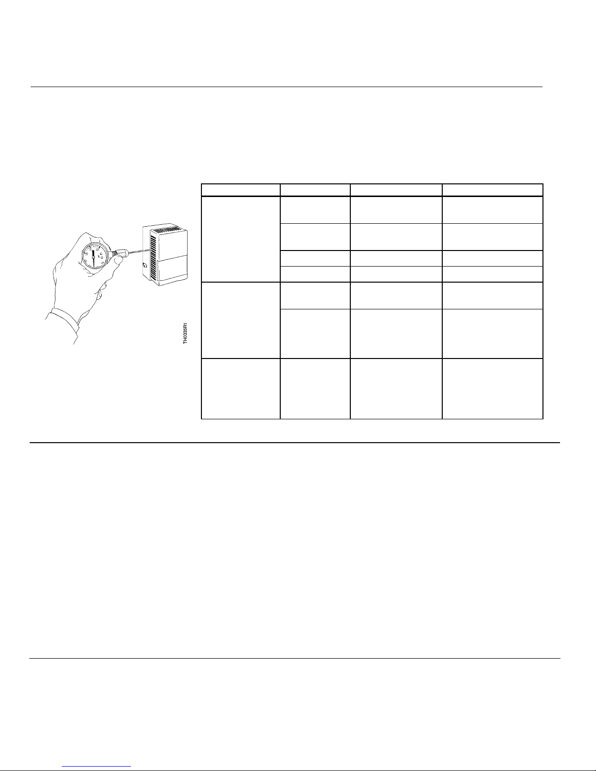
Troubleshooting Before troubleshooting thermostat per Table 4, make certain there is clean dry supply air
at 18 psi (124 kPa) for cooling and 25 psi (172 kPa) for heating. Use test probe gauge
and needle adapter to measure control pressure at thermostat test port.
The output pressure test port is accessible without removing the thermostat cover
through the 8th opening from the top left side for two-pipe thermostats.
Table 3. Troubleshooting Guide.
Problem Check Cause Action
Air supply Low supply
pressure As required
Nozzle or
flapper Dirt on nozzle or
flapper Clean nozzle or
replace thermostat
Restrictor Clogged restrictor Replace restrictor
Control pressure
stays at
approximately
zero
Calibration Out of calibration Recalibrate
Nozzle Clogged nozzle
Clean nozzle or
replace thermostat
Control pressure
stays at
approximately
supply pressure Calibration Dirt on either supply
or exhaust valve
seat
Alternately close and
open nozzle by gently
pushing down the
bimetal
Figure 9. Accessing Output
Pressure Test Port.
Excessive air
leakage from
exhaust port on
left side of
thermostat
Supply and
return line
connection
Connections are
interchanged or
connection to port is
incorrect
As required
Chassis Tube
Connector and
Restrictor Plate
Replacement
1. Remove thermostat chassis from wall. Terminal does not have a ball check valve.
NOTE: You must close off the supply air. For example, use a connector with the supply air
terminal plugged.
2. Remove two Phillips head screws from connector on back of thermostat chassis. Pull
connector out of recess. If necessary, pry connector loose with a screw driver, but be
careful not to damage restrictor plate and gasket.
3. Remove gasket from under connector. Remove restrictor. Remove second gasket from
under restrictor.
4. Use restrictor replacement kit 192-321 to replace gasket, restrictor, and second gasket.
NOTE: The restrictor plate is keyed to ensure proper orientation during installation.
5. Remove filters from existing connector and insert in new connector. Or, if filters are
dirty, use restrictor replacement kit 192-321 to replace filters.
6. Use chassis tube connector replacement kit 192-525 to replace connector and mounting
screws.