Document No. 129-078
Installation Instructions
September 23, 2009
Information in this publication is based on current specifications. The company reserves the right to make changes in specifications and models
as design improvements are introduced. Free Energy Band is a trademark of Siemens Industry, Inc. Product or company names mentioned
herein may be the trademarks of their respective owners. © 2009 Siemens Industry, Inc.
Building Technologies Division
Buffalo Grove, IL 60089-4513
USA
Your feedback is important to us. If you have
comments about this document, please send
Document No. 129-078
Printed in the U.S.A
Page 4 of 4
Heating Calibration
1. If not already done, remove the cover using the
calibration tool. Verify that the room temperature
is between 70°F and 80°F (21°C and 27°C).
2. Verify that the supply pressure is 25 psi
(172 kPa). Set the heating dial to the room
temperature by turning the exposed adjustment
knob or using a hex key as shown. Allow the
thermostat to stand for about five minutes to
adjust to the new setting.
3. Moisten the needle and insert the test gauge and
needle adapter in the heating test port (Figure 5).
Read the control pressure.
4. Check the control pressure. If it does not read 7
to 8 psi (48 to 55 kPa), turn the calibration screw
(Figure 4) using the calibration tool or a 1/8-inch
(3.2 mm) wrench until the pressure is 7 to 8 psi
(48 to 55 kPa). The sensing element is now in
calibration and the set point can be changed to
the desired room temperature.
Troubleshooting
Before troubleshooting the thermostat (see Table 1),
make certain there is clean dry supply air at 18 psi
(124 kPa) minimum. Use the test probe gauge and
needle adapter to measure the control pressure at
the output pressure test port (Figure 5). The output
pressure test port is accessible without removing the
thermostat cover through the 8th opening from the
top as follows:
•For one-pipe thermostats, the test port is on
the right side.
•For two-pipe thermostats, the test port is on
the left side.
If you use the wrong test port,
thermostat damage can occur and
result in replacement of the device.
Table 1. Troubleshooting Guide.
Problem Check Cause Action
Control pressure
stays at
approximately
zero
Air supply Low supply
pressure As required
Nozzle or
flapper Dirt on nozzle or
flapper Clean nozzle or
replace
thermostat
Restrictor Clogged restrictor Replace
restrictor
Calibration Out of calibration Recalibrate
Control pressure
stays at
approximately
supply pressure
Nozzle Clogged nozzle Clean nozzle or
replace
thermostat
Calibration Dirt on either
supply or exhaust
valve seat
Alternately close
and open nozzle
by gently
pushing down
the bimetal
Excessive air
leakage from
exhaust port on
left side of
thermostat
Supply and
return line
connection
Connections are
interchanged or
is incorrect
As required
References
Free Energy Band TH193-4, TH193HC
Heating/Cooling Room Thermostat Technical
Instructions
155-068P25
TB 214, TH192 Adapter Kits Technical Bulletin 155-231P25
TB 237, Accessories for Installation of TH192,
Free Energy Band TH193, or TH194 Room
Thermostats Technical Bulletin
155-244P25
Powerstar Thermostat Covers Color Reference
Guide 152-178P10
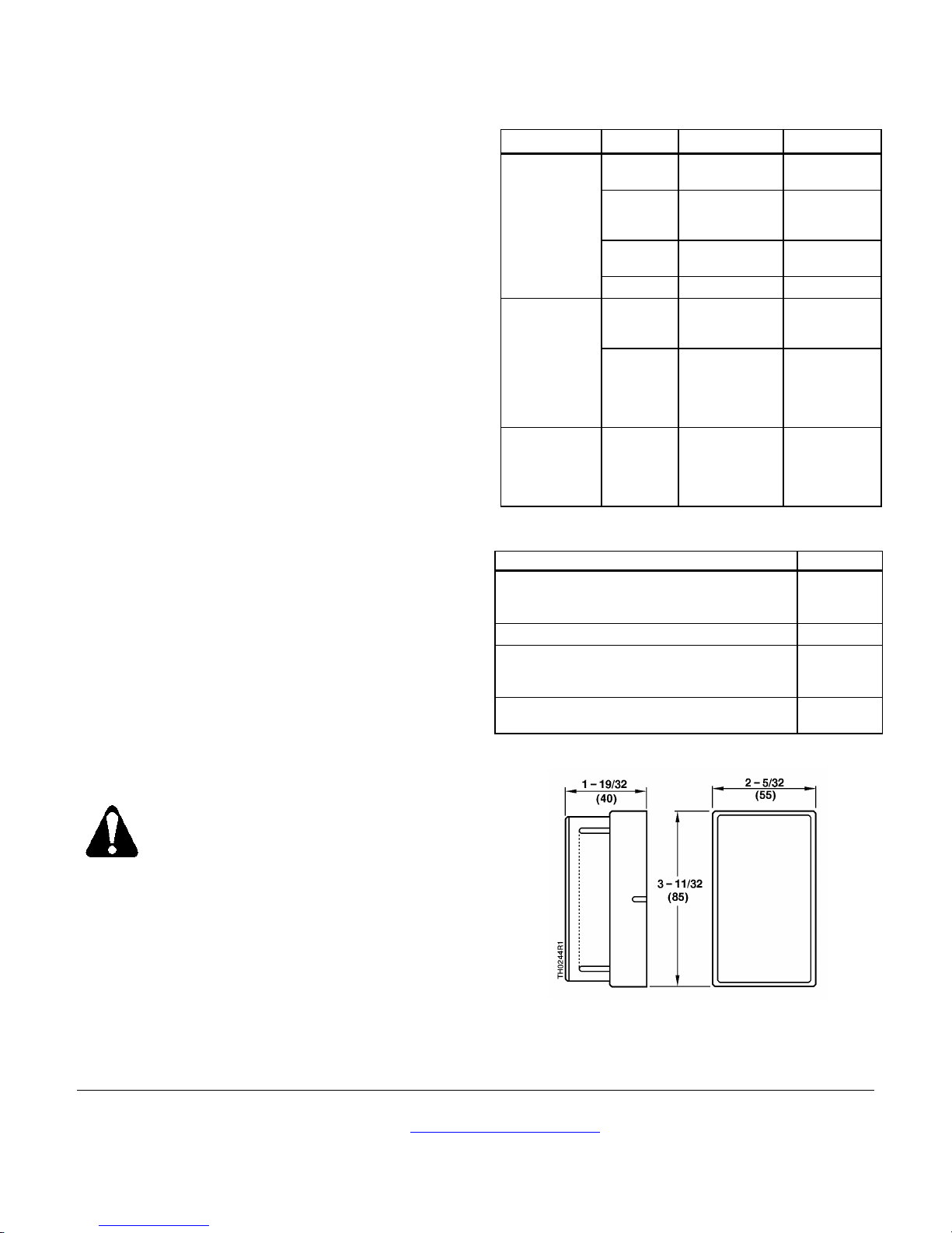
Dimensions
Figure 6. TH193 HC Dimensions in Inches (Millimeters).