manuals.online logo
Brands
  1. Home
  2. •
  3. Brands
  4. •
  5. Siemens
  6. •
  7. Water Pump
  8. •
  9. Siemens SINAMICS V50 User manual

Siemens SINAMICS V50 User manual

SIEMENS
1
1 SINAMICS V50 converter
Operating Instructions, 04/2022, FW V1.0, A5E44777205B AB
FUNDAMENTAL SAFETY INSTRUCTIONS
General safety instructions
WARNING
Electric shock and danger to life due to other energy sources
Touching live components can result in death or severe injury.
Only work on electrical devices when you are qualified for this job.
Always observe the country-specific safety rules.
Generally, the following six steps apply when establishing safety:
Prepare for disconnection. Notify all those who will be affected by the procedure.
Isolate the drive system from the power supply and take measures to prevent it being switched back on again.
Wait until the discharge time specified on the warning labels has elapsed
Check that there is no voltage between any of the power connections, and between any of the power connections
and the protective conductor connection.
Check whether the existing auxiliary supply circuits are de-energized.
Ensure that the motors cannot move.
Identify all other dangerous energy sources, e.g. compressed air, hydraulic systems, or water. Switch the energy
sources to a safe state.
Check that the correct drive system is completely locked.
After you have completed the work, restore the operational readiness in the inverse sequence.
WARNING
Risk of electric shock and fire from supply networks with an excessively low impedance
Excessively high short-circuit currents can lead to the protective devices not being able to interrupt these short-
circuit currents and being destroyed, and thus causing electric shock or a fire.
Ensure that the prospective short-circuit current at the line terminal of the inverter does not exceed the breaking
capacity (SCCR or Icc) of the protective device used.
Fundamental safety instructions
2 SINAMICS V50 converter
Operating Instructions, 04/2022, FW V1.0, A5E44777205B AB
WARNING
Electric shock if there is no ground connection
For missing or incorrectly implemented protective conductor connection for devices with protection class I, high
voltages can be present at open, exposed parts, which when touched, can result in death or severe injury.
Ground the device in compliance with the applicable regulations.
WARNING
Electric shock due to connection to an unsuitable power supply
When equipment is connected to an unsuitable power supply, exposed components may carry a hazardous
voltage. Contact with hazardous voltage can result in severe injury or death.
Only use power supplies that provide SELV (Safety Extra Low Voltage) or PELV- (Protective Extra Low Voltage)
output voltages for all connections and terminals of the electronics modules.
WARNING
Electric shock due to equipment damage
Improper handling may cause damage to equipment. For damaged devices, hazardous voltages can be present
at the enclosure or at exposed components; if touched, this can result in death or severe injury.
Ensure compliance with the limit values specified in the technical data during transport, storage and operation.
Do not use any damaged devices.
3 SINAMICS V50 converter
Operating Instructions, 04/2022, FW V1.0, A5E44777205B AB
PRODUCT INTRODUCTION 2
2.1 Product Nameplate Description
1 Article number
2 Product serial number
3 Motor data
4 Net weight
5 Degree of protection
2.2 Model Description
The digits and letters of the drive model number on the nameplate indicate
information such as the product series, power supply class, power ratings and
software/hardware versions.6SL3620-2YE36-0UB0 means this model can be used as
37kW heavy duty 45kW normal duty.
Product introduction
4 SINAMICS V50 converter
Operating Instructions, 04/2022, FW V1.0, A5E44777205B AB
SINAMICS V50 infrastructure drives for HVAC/Water/Wastewater
37 kW to 250 kW (50 to 400 hp)
SINAMICS V50 infrastructure drives for HVAC/Water/Wastewater
Selection and ordering data
SINAMICS
V
50
drives Degree of protection IP20/UL Open Type 380 ... 480 V 3 AC Configuration with line
-
side
components (see right page)
Rated
power
)
Rated
output
current

)
Base
−
load
current
I


)
Rated
input
current

)
Frame
size
SINAMICS V50
Degree of protection
IP20/UL Open Type
without integrated line filter
400V 480V 400V 480V 400V 480V 400V
kW hp A A A A A Article No.
380…480V 3AC Rated pulse frequency 4kHz≤90kW, 2kHz for 110kW to 250kW Input frequency 47…63 Hz
37 50 75 65 60 52 68 FSD 6SL36 0- YE36- U
0
45 60 90 77 75 65 84 FSE 6SL36 0- YE38- U
0
55 75 110 96 90 77 103 FSE 6SL36 0- YE40- U
0
75 100 150 129 115 101 134 FSF 6SL36 0- YE42- U
0
90 125 176 154 143 122 162 FSF 6SL36 0- YE44- U
0
110 150 210 185 183 161 205 FSF 6SL36 0- YE46- U
0
132 200 250 240 205 180 233 FSF 6SL36 0- YE48- U
0
160 250 300 300 248 238 281 FSG 6SL36 0- YE50- U
0
200 300 380 371 312 312 350 FSG 6SL36 0- YE52- U
0
250 400 470 470 363 354 409 FSG 6SL36 0- YE54- U
0
Article No. supplements
Environmental class/harmful chemical substances acc. to IEC 60721-3-3: 2002
Class 3C2 – delivery ex stock 2
Class 3C3 * 3
Operator Panel
With BOP-3 Basic Operator Panel (numeric display) 4
Extension with SINAMICS V50 I/O Extension Module
Without extension – delivery ex stock 0
Line filter
Without integrated line filter – delivery ex stock U
Communication
USS, Modbus RTU, BACnet MS/TP B
5 SINAMICS V50 converter
Operating Instructions, 04/2022, FW V1.0, A5E44777205B AB
WIRING SYSTEM 3
3.1 Wiring diagrams
Connecting converters FSD...FSG and their optional components
3.2 Description of Peripheral Devices for Main Circuit
Circuit breaker
The capacity of the circuit breaker shall be 1.5 - 2 time of the rated current of the
drive. The time features of the circuit breaker shall fully consider the time features of
the drive overload protection.
Leakage circuit breaker
Because the drive output is the high-frequency pulse voltage, there will be high-
frequency leakage current. Specialized leakage circuit breaker shall be installed at the
input end of the drive. В type leakage circuit breaker is suggested, and the leakage
current value shall be set as 300mA.
Contactor
Frequent open and close of contactor will cause drive failure, so the highest
frequency for the open and close of contactor shall not exceed 10 times/min. When
braking resistor is used, to protect the braking resistor from over-heat damage,
thermal protection relay shall be installed to control the disconnect of the contactor
at power supply side
Input AC/DC reactor
The drive power supply capacity shall be more than 600kVA or 10 times of the drive
capacity.
If there is switch type reactive-power compensation capacitor or load with silicon
control at the same power line, there will be high peak current flowing into drive
power input circuit, causing the damage of the rectifier components.
Wiring system
6 SINAMICS V50 converter
Operating Instructions, 04/2022, FW V1.0, A5E44777205B AB
When the voltage unbalance of the three-phase power supply exceeds 3%, the
rectifier component will be damaged.
The input power factor of the drive is required to be higher than 90%. In case of
above situations, install the AC reactor at the input end of the drive or DC reactor to
the DC reactor terminal.
Input noise
The input noise filter can reduce the noise that flows from the power supply to the
drive or the drive to power supply.
Thermal protection relay
Although the drive has motor overload protection function, when one drive drives
two or more motors or multi pole motors, to prevent the motor over temperature
failure, thermal protection relay shall be installed between the drive and each motor,
and the motor overload protection parameter FC.00 shall be set as “0” (motor
protection disabled).
Output noise filter
When the noise filter is applied to the output side of drive, the conduction and
radiation interference can be reduced.
Output AC reactor
When the cable connecting the drive and the motor is longer than 100m, it is
suggested to install AC output reactor to suppress the high-frequency oscillation to
avoid the damage to motor insulation, large leakage current and frequent drive
protective actions.
3.3 Attention for Main Circuit Wiring
Power Supply Wiring
It is forbidden to connect the power cable to the drive output terminals; otherwise,
the internal components of the drive will be damaged.
To facilitate the input side over current protection and power failure maintenance,
the drive shall connect to the power supply through the circuit breaker or leakage
circuit breaker and contactor.
Please confirm that the power supply phases, rated voltage are consistent with that
of the nameplate, otherwise, the drive may be damaged.
3.4. Motor Wiring
It is forbidden to short circuit or ground the drive output terminals; otherwise the
internal components of the drive will be damaged.
Wiring system
7 SINAMICS V50 converter
Operating Instructions, 04/2022, FW V1.0, A5E44777205B AB
Avoid short circuit the output cable and the drive enclosure, otherwise there is the
risk of electric shock.
It is forbidden to connect the output terminals of the drive to the capacitor or LC/RC
noise filter with phase lead, otherwise, the internal components of the drive may be
damaged.
When contactor is installed between the drive and the motor, it is forbidden to
switch on/off the output contactor during the running of the drive; otherwise, there
will be large current flowing into the drive, triggering the drive protection action.
Length of cable between the drive and motor
If the cable between the drive and the motor is too long, the higher order harmonic
leakage current will cause impact on the drive and the peripheral devices. It is
suggested that output AC reactor be installed when the motor cable is longer than
100m, and that carrier frequency be set as follows:
Cable length
between drive and
motor
Less than 50 m Less than 100 m More than 100 m
Carrier frequency
(F0.15) Less than 10kHz Less than 6kHz Less than 4kHz
3.4.1 Grounding Wiring
The drive will produce leakage current. The higher the carrier frequency is, the larger
the leakage current will be. The leakage current of the drive system is more than
3.5mA, and the exact value of the leakage current is determined by the site
conditions. To ensure the safety, the driver and the motor must be grounded.
The grounding resistance shall be less than 10ohm. For the grounding wire diameter
requirement, refer to 8.7 Model selection of system Do not share grounding wire
with the welding machine and other power equipment.
3.4.2 Countermeasures against conduction and radiation interference
When the input noise filter is installed, the wire connecting the filter to the drive
power input tenninal shall be as short as possible.
The filter enclosure and mounting cabinet shall be large area reliably grounded to
reduce the back-flow impedance of the noise current Ig.
The wire connecting the drive and the motor shall be as short as possible.
The motor cable adopts 4-core cable, among which the grounding wire shall be one
end grounded at the drive side, the other end connected to the motor enclosure.
Wiring system
8 SINAMICS V50 converter
Operating Instructions, 04/2022, FW V1.0, A5E44777205B AB
The motor cable shall be sleeved into the metal tube.
The input power wire and output motor wire shall be kept away from each other if
possible. The equipment and signal cables vulnerable to interference shall be kept far
away from the drive.
Key signal cables shall adopt shielding cable. It is suggested that the shielding layer
shall be grounded with 360-degree grounding method and sleeved into the metal
tube. The signal cable shall be kept far away from the drive power input wire and
output motor wire. If the signal cable must cross the power input wire and output
motor wire, they shall be laid orthogonal.
When analog input of voltage or current is adopted for remote frequency setting,
twisted shielding cable shall be used. The shielding layer shall be connected to the
grounding terminal PE of the drive, and the signal cable shall be no longer than 50m.
The wiring of TA/TB/TC shall be separated from wiring of other main circuit terminals.
It is forbidden to short circuit the shielding layer and other signal cables or
equipment.
9 SINAMICS V50 converter
Operating Instructions, 04/2022, FW V1.0, A5E44777205B AB
INSTALLATION 4
4.1 Environment
Avoid installing the product in the sites with oil mist, metal powder and dust.
Avoid installing the product in the sites with hazardous gas and liquid, and
corrosive, combustible and explosive gas.
Avoid installing the products in salty sites.
Do not install the product in the sites with direct sunlight.
Do not mount the product on the combustible materials, such as wood.
Keep the drilling scraps from falling into the inside of drive during the installation.
Mount the product vertically in the electric control cabinet, mount the cooling fan
or air conditioner to prevent the ambient temperature from rising to above 40 °C.
For the sites with hash environment, it is recommended to mount the drive heat
sink outside the cabinet.
4.2 Mounting Direction and Space
In order not to reduce the drive cooling effect, the drive must be mounted vertically,
and certain space must be maintained, as shown below (1):
Mounting direction and space installation diagram
When installing multiple drives vertically upside and downside, the air deflector is
required as figure above (2).
Installation
10 SINAMICS V50 converter
Operating Instructions, 04/2022, FW V1.0, A5E44777205B AB
4.3 Wiring preparation for driver
SINAMICS V50 wiring preparation
Dismantled/mounted keypad: Push out keypad like fig. below (1), then take off it
along the ‘P’ direction. Mount it along the opposite direction.
Wiring preparation: Loosen the clip 3/4, then open along the ‘O’ direction, take off
along the ‘P’ direction.
Take off along the opposite direction.
SINAMICS V50 Metal-sheet enclosure type A.
The АС-in and AC-out of some drivers are at two sides of driver.
Dismantling covert: dismantle the screw 1/2, open covert along ‘O’ direction, and
take off it along ‘P’ direction.
Dismantling cover2: dismantle the screw 3/4, open cover2 along ‘O’ direction, take
off it along ‘P’ direction.
SINAMICS V50 Metal-sheet enclosure type В.
Dismantling cover: dismantle the screw 3/4, open cover2 along ‘O’ direction, take off
it along ‘P’ direction. The wiring holes at two sides of driver, break it to create holes
for wiring
Installation
11 SINAMICS V50 converter
Operating Instructions, 04/2022, FW V1.0, A5E44777205B AB
4.4 Terminal description
SINAMICS V50 - 6SL3620-2YE36-0UB0 ~ 6SL3620-2YE46-0UB0
Terminal diagram
of main circuit
Terminal Symbol Terminal description
Grounding terminal PE
R, S Single-phase AC input terminals
R, S, T Three-phase AC input terminals
(+), PB Terminals reserved for braking resistor
U, V, W Three-phase AC output terminals
SINAMICS V50 - 6SL3620-2YE48-0UB0 ~ 6SL3620-2YE54-0UB0
Terminal
diagram of main
circuit
Terminal Symbol Terminal description
Grounding terminal PE
R, S, T Three-phase AC input terminals
(-), (+) DC bus - + terminals for common bus DC input
P1, (+) Short circuited with copper plate as factor setting
U, V, W Three-phase AC output terminals
Installation
12 SINAMICS V50 converter
Operating Instructions, 04/2022, FW V1.0, A5E44777205B AB
4.5 Control Terminal Wiring of SINAMICS V50
Installation
13 SINAMICS V50 converter
Operating Instructions, 04/2022, FW V1.0, A5E44777205B AB
4.6 SINAMICS V50 Standard configuration of control circuit terminals
Type Termin Terminal function Technical specification
Digital
input X1
X3
Multi-functional
input terminals 1 -3
Optical-isolator input Frequency
range: 0 - 200Hz
Voltage range: 0 - 24V
X4
X5
Multi-functional
input or Single pulse
input 4, 5
Multi-functional input: same as X1 -
X3
Single Pulse input: 0.1Hz - 50kHz
Voltage range: 0 - 24V
COM
Multi-functional
input terminals
common end
Internal isolated with GND
Digital
output 24V 24V
24V±5%, Maximum load :200mA,
with overload and short circuit
protection
Y1 Open collector
output 1
Optical-isolator output maximum
output current: 50mA
Output voltage range: 0 - 24V
DO
Open collector or
high-speed pulse
output
Output frequency: 0 - 50kHz
Can be used as the normal open
collector.
COM
Open collector
output common
end
Internal isolated with GND
Analog
input 10V Analog input
reference voltage
Open circuit voltage up to 11V;
Internal isolated with COM;
Maximum load 30mA, with overload
and short circuit protection
AI1 Analog input
channel 1
Input Voltage range: 0 - 10V
Input impedance: 100kOhm
AI2 Analog input
channel 2
Input Voltage range: 0 - 10V
Input impedance: 100kOhm
Input current range: 0-30mA
Current input impedance: 500Ohm,
0 - 20mA or 0 - 10V analog input can
be selected through DIP switch
SW2
GND Analog grounding Internal isolated with COM
Analog
output AO1 Analog output 1
0/4 - 20mA: Allow output impedance
200-500Ohm
0-10V: Allowed output impedance
>10kOhm.
Installation
14 SINAMICS V50 converter
Operating Instructions, 04/2022, FW V1.0, A5E44777205B AB
With SC protection, 0 - 20mA or
0 - 10V analog output can be
selected through DIP switch SW1
GND Analog grounding Internal isolated with COM
Relay
output TA/TB/TC
Relay output 1 ТА—ТВ: NC; TA—TC: NO Contact
capacity: 250VAC/1A, 30VDC/1A
RS485 485+ 485 differentials
positive
Rate:
1200/2400/4800/9600/19200/38400
bps
Max. parallel 127 No.s;
SW3 select adapted resistor;
Max. Length 500m. (twisted
shielding cable)
485- 485 differential
negatives
GND 486 shielding
grounding Internal isolated with COM
Terminal strips with wiring example
Installation
15 SINAMICS V50 converter
Operating Instructions, 04/2022, FW V1.0, A5E44777205B AB
SINAMICS V50 Control Circuit Connection
Wiring mode of analog input terminal
T568B standard
Pin No. Color
1 Write/Orange
2 Orange
3 Greer/White
4 Blue
5 Blue/ While
5 Green
7 Brown/White
8 Brown
Installation
16 SINAMICS V50 converter
Operating Instructions, 04/2022, FW V1.0, A5E44777205B AB
4.7 Control board schematic drawing
Control board schematic drawing
Z: DIP switches
CN3: Terminals 1 for options PCBA
CN5: Terminal for drive PCBA
Earthing: Earthing point of control PCBA
SINAMICS V50 Control circuit periphery accessories selection
Terminal codes Terminal
screw
Tightening
torque (Nm)
Wire
Spec.mm2 Type of Wire
10V, AI1, AI2, AO1, GND
485+, 485- М3 0.5-0.6 0.75 Twisted pair
Shielded
cable
24V X1, X2, X3, X4, X5,
COM, Y1, DO, COM, ТА,
ТВ
,
TC
М3 0.5-0.6 0.75 Shielded
cable
Installation
17 SINAMICS V50 converter
Operating Instructions, 04/2022, FW V1.0, A5E44777205B AB
SINAMICS V50 DIP switch setting instruction
Terminal Function Default
AI2 I for current input(0/4-20mA);
V for voltage input (0- 10V) 0 - 10 V
AO1 I for current output(0/4-20mA);
V for voltage output (0 - 10V) 0 - 10 V
RS485 User selected resistor ON
18 SINAMICS V50 converter
Operating Instructions, 04/2022, FW V1.0, A5E44777205B AB
OPERATION AND APPLICATION 5
5.1 Keypad
The keypad of SINAMICS V50 series drives is the main unit of accepting command,
displaying and modifying parameters. The LED keypad outline is as follows.
LED keypad model name: BOP-3
Operation and application
19 SINAMICS V50 converter
Operating Instructions, 04/2022, FW V1.0, A5E44777205B AB
Keypad button description
Keys Name Function
PRG Programming key Entry and exit of primary menu
ENTER Confirmation key Enter the next level menu or confirm the data
setting
A Increase key Increase of the value or function code
V Decrease key Decrease of the value or function code
>> Shift key
Select the to be displayed parameters in turn
under stop interface or running interface;
Choose the to be modified digits when setting
parameters.
RUN Running key Run the drive under keypad operation mode.
STOP Stop/reset
Stop the drive at running status; Reset
operation in the fault alarm status. Its function
is limited to setting of code FE.02.

Other Siemens Water Pump manuals

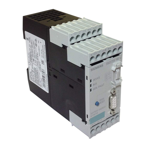
Siemens SIMOCODE pro V User manual

Siemens

Siemens SIMOCODE pro V User manual

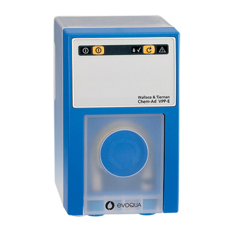
Siemens Wallace & Tiernan Chem-Ad VPP User manual

Siemens

Siemens Wallace & Tiernan Chem-Ad VPP User manual

Popular Water Pump manuals by other brands

Makita DVP180 instruction manual

Makita

Makita DVP180 instruction manual

BCS 921WP147 Installation, operation, and parts manual

BCS

BCS 921WP147 Installation, operation, and parts manual

PFT RITMO L Eco operating manual

PFT

PFT RITMO L Eco operating manual

Pfeiffer Vacuum OKTA 250 operating instructions

Pfeiffer Vacuum

Pfeiffer Vacuum OKTA 250 operating instructions

Harbor Freight Tools PacificHydroStar Owner's manual & safety instructions

Harbor Freight Tools

Harbor Freight Tools PacificHydroStar Owner's manual & safety instructions

PondMAX FP Series instruction manual

PondMAX

PondMAX FP Series instruction manual

HIBLOW hp-150 instruction manual

HIBLOW

HIBLOW hp-150 instruction manual

Valex PJ370B operating instructions

Valex

Valex PJ370B operating instructions

JABSCO 23920-2403 installation instructions

JABSCO

JABSCO 23920-2403 installation instructions

Crane PROSSER SED Series Installation and operation manual

Crane

Crane PROSSER SED Series Installation and operation manual

Rossmax V5 user manual

Rossmax

Rossmax V5 user manual

Wilo Multivert MVISE-3G Installation and operating instructions

Wilo

Wilo Multivert MVISE-3G Installation and operating instructions

WITA go.future light 40 series TRANSLATION OF THE ORIGINAL INSTALLATION AND OPERATING INSTRUCTIONS

WITA

WITA go.future light 40 series TRANSLATION OF THE ORIGINAL INSTALLATION AND OPERATING INSTRUCTIONS

Espa ACUARIA07 instruction manual

Espa

Espa ACUARIA07 instruction manual

Star 025576 quick start guide

Star

Star 025576 quick start guide

GORMAN-RUPP PUMPS SUPER T T4A60S-4LE2T FT4 Series Installation, operation, and maintenance manual with parts list

GORMAN-RUPP PUMPS

GORMAN-RUPP PUMPS SUPER T T4A60S-4LE2T FT4 Series Installation, operation, and maintenance manual with parts list

Fieldmann FVC 5015 EK user manual

Fieldmann

Fieldmann FVC 5015 EK user manual

GÜDE HWW 900 GC Translation of the original instructions

GÜDE

GÜDE HWW 900 GC Translation of the original instructions

manuals.online logo
manuals.online logoBrands
  • About & Mission
  • Contact us
  • Privacy Policy
  • Terms and Conditions

Copyright 2025 Manuals.Online. All Rights Reserved.