Siensor D100 Series User manual

PASSPORT
Siensor D100 Series
Liquid Level Sensors
ПАСПОРТ
说明书
www.siensor.com

2
1. Overview
2. Technical Specications
3. Pacakage Contents
4. Mounting Dimensions
5. Mounting Guidelines
5.1. The Sensor Connector Pin Assignments
for Connection to an External Device
5.2. Connecting the Liquid Level Sensor
to an External Device
5.3. Sealing
5.3.1. Installing a Protective Seal
on the Liquid Level Sensor
5.3.2. Installing a Protective Sealing
on the Connector
6. Opeartion Guidelines
7. Storage and Service Requirements
8. Utilization
3
4
6
9
12
14
15
16
16
17
18
19
19
TABLE OF CONTENTS

3
1. OVERVIEW
Siensor D107, D110 and D115 liquid level sensors
(hereinafter referred to as LLS) are intelligent devices,
designed for accurate measurement of temperature
and fuel level in vehicle tanks as well as stationary
reservoirs, which are not subject to the explosion
protection requirements for equipment. Siensor D107
D110 and D115 digital capacitive sensors provide data
communication with an external device via RS-232 or
RS-485 interfaces.
Siensor D107 has a measuring section of 700 mm.
Siensor D110 has a measuring section of 1000 mm.
Siensor D115 has a measuring section of 1500 mm.
The sensor allows for the measuring probe to be cut
to 20% of its original length.
Changing the length of the LLS measuring probe
might aect the extent of measurement error!
4
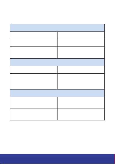
Power supply:
Power supply voltage, V 7 to 50
Power consumption, W max 0.4
Current consumption, mA,
max 40
Interaction interface with external devices:
Interface RS-232 and RS-485
Data rate, bps 1200, 2400, 4800, 9600,
19200, 38400, 57600,
115200
Relative reduced measurement error:
Within the range of –60°С
to +60°С, % max ±0.8
Within the range of –60°С
to +80°С, % max ±1.0
2. TECHNICAL SPECIFICATIONS
Table 2.1 Technical specications
5
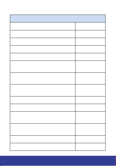
General information:
Temperature measurement range, °С –55 to +80
Temperature measurement error, °С max ±2
Fuel level measurement range 1 to 4095
Measurement interval 1 sec
Operating temperature, °С –40 to +80
Extended operating temperature
range*, °С –55 to +80
Minimum permissible
temperature**, °С –60
Maximum permissible
temperature**, °С +85
Dust and water protection IP69К
Interval of automatic data output, sec 1 to 255
Size of the measurement results
internal lter 0 to 20
Mean time between the sensor
failures, h, minimum 100000
Average lifetime, years, minimum 8
D107 Dimensions, mm 125×74×730
Continuation of Table 2.1 Technical specications
This manual suits for next models
3
Table of contents
Languages:
Other Siensor Accessories manuals


