Sierra Pacific M1-D User manual

M1-D MANUAL
REVISION 1.3.2
SIERRA PACIFIC INNOVATIONS CORP
6620 S. TENAYA WAY 100
LAS VEGAS, NV 89113
702-369-3966
WWW.X20.ORG

Sierra Pacific Innovations Corp 1.3.2
M1-D User’s Guide 2
TABLE OF CONTENTS
!"##$%&'()#*+('$#,#-./+0(%*(#"""""""""""""""""""""""""""""""""""""""""""""""""""""""""""""""#1!
2"##%3+4(#(5'#.!67#"""""""""""""""""""""""""""""""""""""""""""""""""""""""""""""""""""""""""""""""""#8!
2.1!FEATURES!..............................................................................................!5!
2.2!FUNCTIONS!............................................................................................!6!
Thermal(Imaging(Sensor(....................................................................(6!
Visual(CCD(Sensor(..............................................................................(6!
Laser(Indicator(...................................................................................(6!
Thermal(Zoom(....................................................................................(6!
Inverted(Operation(.............................................................................(7!
Auto(Tours(..........................................................................................(7!
On(Screen(Display(Symbology(............................................................(7!
2.3!TECHNICAL!SPECIFICATIONS!......................................................................!8!
9"##-*$(%::%(-+*#""""""""""""""""""""""""""""""""""""""""""""""""""""""""""""""""""""""""""""""""""""""#;!
3.1!DIMENSIONAL!VIEWS!...............................................................................!9!
3.2!MOUNTING!THE!M1=D!.........................................................................!11!
Mounting(Steps(................................................................................(12!
3.3!ELECTRICAL!CONNECTIONS!.....................................................................!13!
Electrical(Steps(.................................................................................(13!
Electrical(Connections(Overview(Diagram(Fig.(1.6(...........................(15!
1"##+/'0%(-+*#""""""""""""""""""""""""""""""""""""""""""""""""""""""""""""""""""""""""""""""""""""""""#!<!
4.1!BASIC!OPERATION!.................................................................................!16!
PelcoKD(Specialty(Command(Mapping(.............................................(16!
Power(On(the(M1KD(.........................................................................(17!
Pan(Tilt(The(M1KD(............................................................................(17!
Select(Video(Source(..........................................................................(17!
Trigger(The(Laser(Pointer(.................................................................(18!
Thermal(Imaging(Sensor(Zoom(........................................................(18!
Thermal(Imaging(Color(Palletes(.......................................................(19!
4.2!ONSCREEN!SYMBOLOGY!.........................................................................!21!
Heading(Indicator(............................................................................(21!
Numeric(Pan(Tilt(Indicator(...............................................................(22!
Cross(Hairs(.......................................................................................(22!
Zoom(Indicators(...............................................................................(22!
Logo(.................................................................................................(22!
Text(String(........................................................................................(22!
Accessing(The(On(Screen(Display(Menu(...........................................(23!
Navigating(The(OSD(Menus(.............................................................(23!

Sierra Pacific Innovations Corp 1.3.2
M1-D User’s Guide 3
Symbology(OSD(Menu(......................................................................(24!
Symbology(Crosshair(Menu(.............................................................(24!
Symbology(Zoomer(Menu(................................................................(25!
Symbology(Pan(Position(Menu(.........................................................(25!
Symbology(Numeric(Position(Menu(.................................................(25!
Symbology(Text(Menu(......................................................................(25!
Symbology(Logo(Menu(.....................................................................(26!
Crosshair(Configuration(Menu(.........................................................(26!
Crosshair(Configuration(Fixed(Type(.................................................(26!
Crosshair(Configuration(Adjustable(Type(.........................................(28!
Crosshair(Configuration(Zoomer(Type(.............................................(28!
Crosshair(Adjust(Menu(.....................................................................(28!
Cross(Grouping(.................................................................................(29!
Crosshair(Adjust(Setting(Crosshair(Positions(....................................(29!
Crosshair(Adjust(Reset(All(Submenu(.................................................(30!
4.3!ADVANCED!OPERATION!.........................................................................!30!
Setting(Preset(Positions(...................................................................(31!
Calling(Preset(Positions(....................................................................(31!
Advanced(Preset(Call(Number(Codes(...............................................(31!
Preset(Call(Number(Code(Table(1.5(..................................................(32!
Preset(81(Video(Switch(.....................................................................(33!
Preset(82(Auto(Scan(.........................................................................(33!
Preset(84(Pattern(Scan(1(..................................................................(33!
Preset(85(Pattern(Scan(2(..................................................................(33!
Preset(86(Pattern(Scan(3(..................................................................(34!
Preset(87(Pattern(Scan(4(..................................................................(34!
Preset(89(Clear(Presets(....................................................................(34!
Preset(90(OSD(On/Off(......................................................................(34!
Preset(94(Remote(Reboot(................................................................(34!
Preset(96(180(Degree(Continuous(Scan(...........................................(35!
Preset(97(360(Degree(Random(Scna(................................................(35!
Preset(98(90(Degree(Continuous(Scan(.............................................(35!
Preset(99(OSD(..................................................................................(35!

Sierra Pacific Innovations Corp 1.3.2
M1-D User’s Guide 4
1. SAFETY NOTES – IMPORTANT
The following safety precautions must be followed carefully. Please take the
time to review the entire manual before operation.
Before installing the M1-D camera system please read this manual carefully
and familiarize yourself with its features and operations.
The installation of the M1-D must be performed by qualified service or
system integrators and shall comply with all local codes.
Before powering on the camera verify the power voltage, current and polarity
are correct.
Route the power, video and control cables in an appropriate manner to avoid
damage to the cable. Make sure the cable is not a trip hazard.
Do not operate the camera outside of the systems specified environmental
range. The M1-D’s working temperature range is -25°C - 70°C. The ambient
humidity limit is <95% non-condensing.
During transportation avoid violent shock and/or vibration to the camera
system.
To prevent electric shock and avoid permanent damage to the M1-D, do not
remove any screws or attempt to disassemble the system housing. There are
no user serviceable parts inside. Contact SPI Corp for service at 702-369-
3966.
Video and RS-485 control cables should be separated from other cables.
Shielding may be necessary in some cases to avoid interference.
NEVER aim the lens of the M1-D at the sun or extremely hot objects. This
may damage the precision thermal sensor.
To clean the M1-D use a soft cloth. For extreme dirt utilize a weak solution
of water and household dish soap. Use only quality lens care tissue or lens
cloth to wipe the windows of the M1-D.
Do not rotate the camera housing manually. Do not hold the camera module
while in operation or try to stop the rotation while in operation. This may
result in a malfunction of the camera.

Sierra Pacific Innovations Corp 1.3.2
M1-D User’s Guide 5
Shield the camera from radiation, X-Ray, Radar or other strong electro-
magnetic sources.
2. ABOUT THE M1-D
The M1-D is an intelligent Pan Tilt Zoom multisensor imaging
platform designed for all weather operation on a variety of
platforms. The M1-D is ideally suited for Vehicle, Vessel or
stationary mounting configurations. The M1-D features a
thermal day/night sensor, a visual light CCD sensor and a laser
indicator. The M1-D PTZ is remotely controlled via optional
accessory keyboards or via user supplied devices that
communicate via RS/485 utlizing the Pelco-D protocol.
2.1 Features
!Fully weatherized housing for outdoor operation, anti-
vibration, anti-corrosion IP66 rated.
!Thermal imaging sensor for detailed imagery in any lighting
condition.
!CCD Visual sensor for target identification.
!Laser indicator for team security and object tracking.
!Continuous 360° pan with 90° tilt range.
!12VDC operation with vehicle cigarette lighter support.
!User adjustable preset positions with auto tour.
!Digital Zoom.
!Compact 4.5” gimbal ball design with a light weight of
approximately 2 lbs. for easy integration into a variety of
platforms.

Sierra Pacific Innovations Corp 1.3.2
M1-D User’s Guide 6
2.2 Functions
Thermal Imaging Sensor
The M1-D is equipped with a next generation LWIR (Long Wave
InfraRed) thermal imaging sensor operating in the 8-12 micron
wavelength. This sensor “sees” heat energy not light. This
unique capability allows you to visualize the world around you
regardless of ambient lighting.
Visual CCD Sensor
The M1-D is equipped with a visual imaging sensor that sees in
the visual light spectrum. This sensor is ideally suited for object
identification and for reading vehicle tags, ship or aircraft
numbers.
Laser Indicator
The M1-D is equipped with a red dot visible light laser pointing
device. The laser can be triggered to pin point areas of interest
to other personal working together as a team.
Thermal Zoom
The M1-D incorporates the latest in Digital thermal zoom
technology. The zoom level can be triggered from the remote
control and increases awareness by factors of 2x, 4x, 8x
(depending on model).

Sierra Pacific Innovations Corp 1.3.2
M1-D User’s Guide 7
Inverted Operation
The standard orientation for the M1-D is in the upright position
with the base plate resting on a surface below (such as a
vehicle roof). The system is capable of inverted operation
wherin the base plate is mounted above (such as in a UAV or
Aircraft). Inverted operation must be ordered from the factory.
Please contact SPI CORP 702-369-3966 to switch to inverted
operation.
Auto Tours
The M1-D can be configured to automatically scan between
selected preset stops. The user defines the stops so that you
can set the system to continuously scan certain areas of
interest. In addition the M1-D can be setup to automatically pan
90°, 180° or 360°.
On Screen Display Symbology
The M1-D has a variety of user adjustable on screen display
symbols that greatly aid in scene visualization. The symbology
includes multiple crosshairs (boresightable to the laser
indicator), zoom FOV indicators, pan position indicator, user
input text string, laser firing indicator and logos. The symbology
is controlled via the onscreen menu system.

Sierra Pacific Innovations Corp 1.3.2
M1-D User’s Guide 8
2.3 Technical Specifications
160x120
320x240
640x480
Thermal Performance
Detector
Microbolometer Long Wave InfraRed
Resolution
160x120
320x240
640x480
Spectral Response
8-12 microns (LWIR)
Thermal Optics
19mm or 25mm
19mm or 25mm
19mm or 25mm
19mm FOV
12° HFOV
24° HFOV
32° HFOV
25mm FOV
9° HFOV
18° HFOV
25° HFOV
Visual Performance
Sensor
1/3” CMOS
Resolution
520 TV Lines
FOV
20° HFOV
Pan Tilt
Pan Range
360° Continuous Rotation
Tilt Range
90° Tilt Range
P/T Speed
PAN:0.05o~240o/sec;TILT:0.03o~160o/sec
Auto Cruise
1-39 preset positions scan in sequential order
Pattern Scans
4 programable routes.
Presets
Up to 100
Interface
Video
Single channel NTSC
Communication
RS/485 2400bps Pelco-D protocol
Environmental
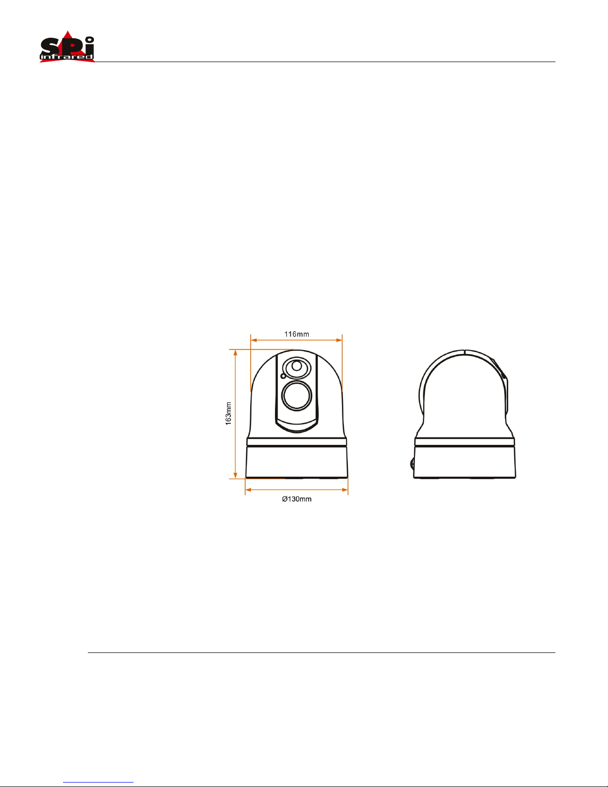
Size
4.5” Gimbal (130mm x 116mm x 163mm)
Weight
2lbs. (19mm system)
Operating Temp.
-25°C to +60°C
Sierra Pacific Innovations Corp 1.3.2
M1-D User’s Guide 9
3. INSTALLATION
This section contains basic installation instructions for the M1-D
multi sensor system. Since the M1-D is designed to be mounted
on a wide range of vehicles, vessels and aircraft we cannot
cover every installation scenario possible. This guide offers the
basic instructions for installation in common applications.
Qualified installation personnel in accordance with all local and
federal codes should carry out all installations.
3.1 Dimensional Views
Fig. 1 Outer dimensions (no stabilization plate)

Sierra Pacific Innovations Corp 1.3.2
M1-D User’s Guide 10
Fig. 1.2 Outer Dimensions (with stabilization plate)
Fig. 1.3 Bottom mounting holes and magnets.

Sierra Pacific Innovations Corp 1.3.2
M1-D User’s Guide 11
Fig. 1.4 Stabilization plate mounting holes
3.2 Mounting The M1-D
First you must decide if the M1-D is to be mounted in the
standard upright position or inverted. In order to mount the
unit inverted you must specify inverted operation at time of
order or send the unit back to SPI Corp for modification.
Inverted operation is normally associated with UAV usage
when mounted to the bottom of Aircraft. M1-D is not aircraft
certified.
The M1-D comes standard with a high strength magnetic base
mount consisting of three high power magnets embedded into
the base of the unit. These magnets are suitable for mounting
the M1-D on metallic surfaces (such as a vehicle roof) for on
road use in non violent conditions. For a more permanent mount
or for use in extreme motion environments you will want to use
the bolt holes on the bottom of the unit to affix the M1-D to a
bracket (of your own fabrication). SPI Corp offers a vibration
mitigation stabilization plate which also acts as a hard mounting
plate for the M1-D. Contact SPI Corp at 702-369-3966 to
purchase this accessory.

Sierra Pacific Innovations Corp 1.3.2
M1-D User’s Guide 12
Mounting Steps
1. Find a suitable flat location that is free from obstruction
on all sides. You will want this area to be parallel with the
ground so as not to skew the image as you pan. Make
sure that the area is firm and not flexible since flexing of
the mounting surface will cause jitter in the video image
during use.
2. If using the magnetic mounts carefully tilt the M1-D into
position. DO NOT PINCH YOUR FINGERS. The
magnets will grab with some force.
3. If using the mounting holes first mount the M1-D to your
mounting fixture then mount the fixture to your surface.
We recommend fabricating a “spider” type bracket that
extends out beyond the edge of the M1-D (see Fig.
1.4.1). If you have access to the underside of your
mounting platform you can mark and drill holes to mount
your bolts through the mounting plate and up into the
bottom of the M1-D.
4. Route the main system cable into the vehicle or other
protected area. Be careful to not put undue strain on the
cable or bend the cable severely.
Fig. 1.4.1 Sample spider mount design. Not to scale.

Sierra Pacific Innovations Corp 1.3.2
M1-D User’s Guide 13
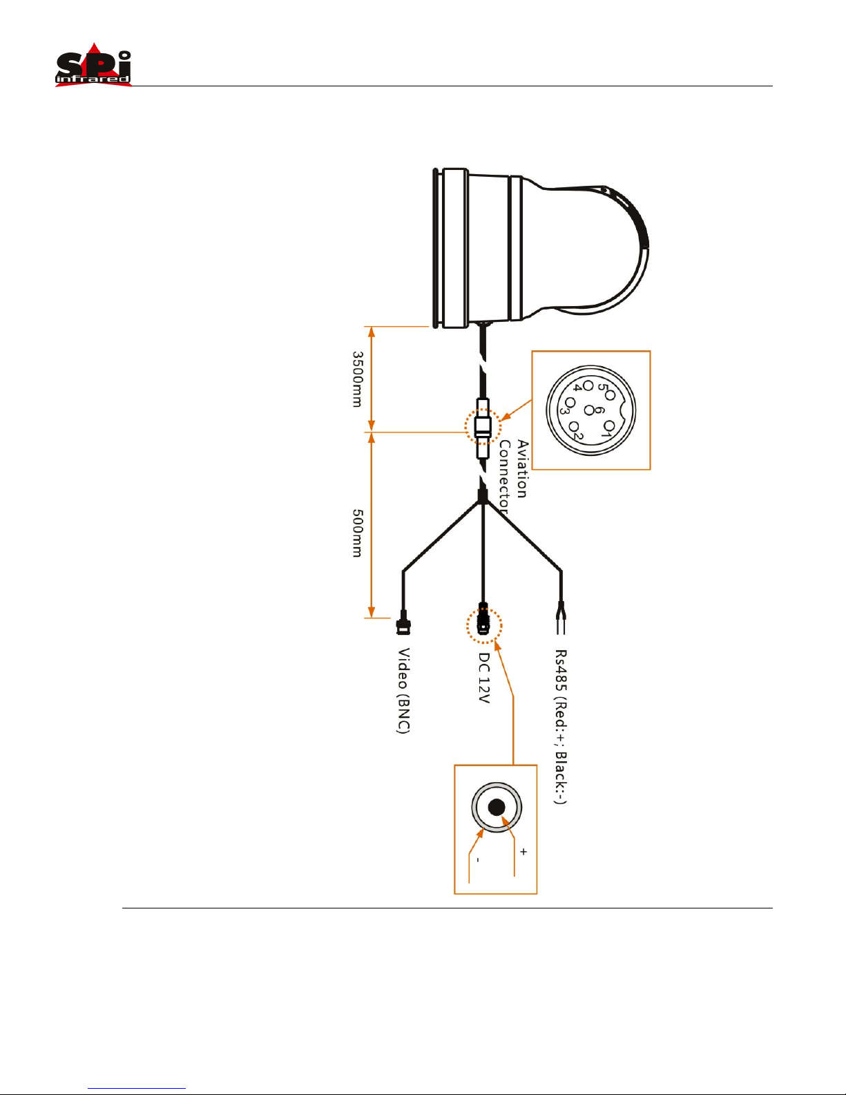
3.3 Electrical Connections
The M1-D operates on 12VDC power typical of most vehicles.
The M1-D is a negative ground system so verify that your
vehicle outputs the correct voltage and polarity. The M1-D
outputs standard NTSC video signal and responds to
commands via 2 wire RS/485 serial interface utilizizing the
Pelco-D protocol at 2400bps. Electrical connections should
always be performed by qualified personel in accordance with
local and federal codes.
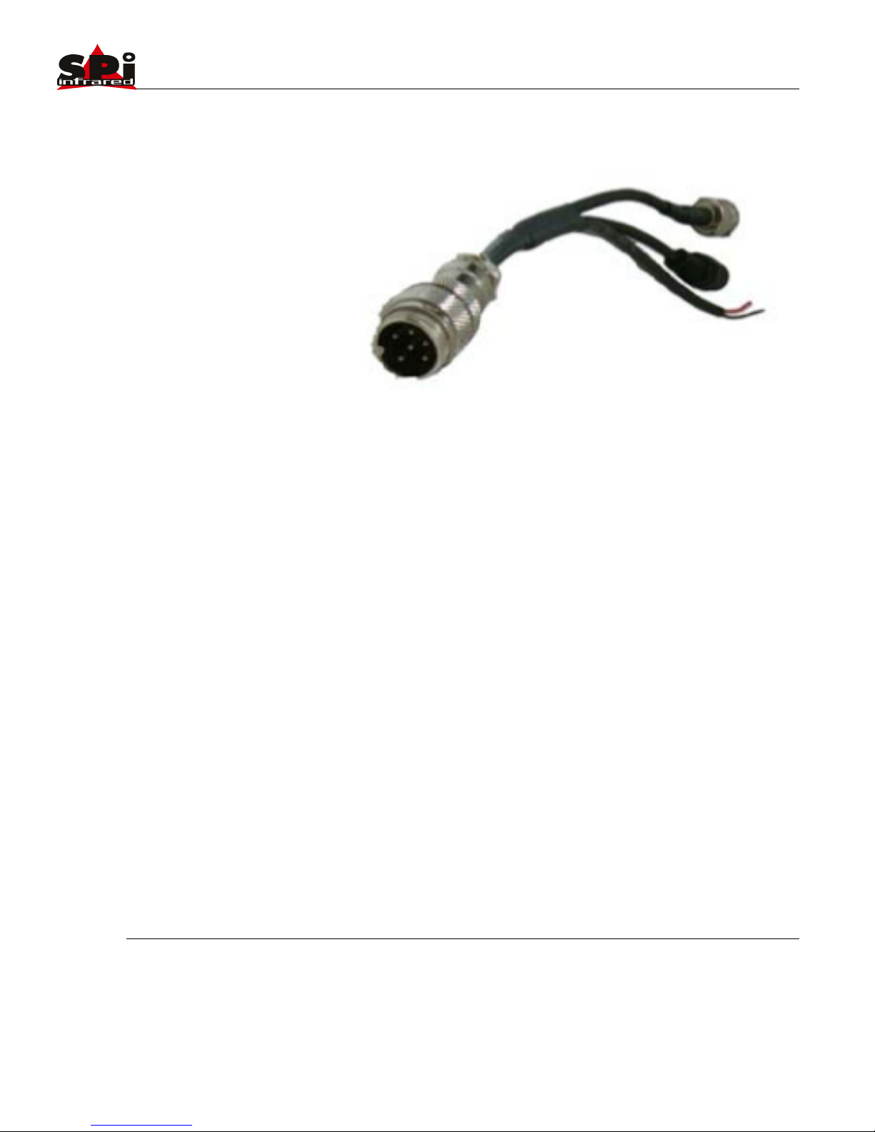
Electrical Steps
1. Review Electrical Connections Overview Diagram (Fig.
1.6)
2. Route main system cable into protected area.
3. Connect the pigtail cable extender (Fig. 1.5) to 12VDC
power. The included pigtail cable extender utilizes a
phono plug type connector and includes a cigarette
lighter adapter. For more permanent installation this
connector can be cut off and hard wired to the vehicle.
OBSERVE POLARITY OR SYSTEM DAMAGE WILL
OCCUR. CONSULT A QUALIFIED ELECTRICIAN.
4. Connect the RS/485 cables to the appropriate port of
your controller. The RS485 leads are red and black in
color. The red wire is RS485 + and the black wire is
RS485 -.
5. Connect the BNC video plug to a suitable NTSC video
monitor.
6. Connect the pigtail cable extender to the main system
cable. The unit will power on when this connection is
made.
There is no ON/OFF switch on the M1-D main system cable.
The system is powered off by removing power from the cable or
disconnecting the M1-D pigtail cable extender from the main
cable. To install a dash mounted or other power switch make
your connection or relay in line with the 12VDC power
connections after the pigtail cable extender.
Sierra Pacific Innovations Corp 1.3.2
M1-D User’s Guide 14
Fig. 1.5 Pigtail Cable Extender.
Sierra Pacific Innovations Corp 1.3.2
M1-D User’s Guide 15
Electrical Connections Overview Diagram Fig. 1.6

Sierra Pacific Innovations Corp 1.3.2
M1-D User’s Guide 16
4. OPERATION
This section contains the information required to operate the
M1-D mult-sensor pan tilt zoom system. Please read and
familiarize yourself with the entire manual before operating the
M1-D system.
4.1 Basic Operation
The M1-D multi sensor pan tilt zoom system is comprised of the
following subsystems.
1. Thermal infrared imaging sensor with dgital zoom and
fixed focus optics.
2. Visual light CMOS sensor with focus free optics.
3. Laser pointer
4. Pan Tilt remote controlled positioning housing.
The M1-D is a remote controlled imaging system that provides
the user with thermal imaging video, daytime video and laser
pointer technology. The system is controlled via joystick or
keyboard controls allowing the user to operate the system
remotely.
Pelco-D Specialty Command Mapping
The various subsystems are controlled via buttons on standard
Pelco-D compliant controllers, DVR’s or computer software.
Special commands exclusive to the M1-D are mapped to
specific Pelco-D commands in order to maximize compatiblitiy.
The M1-D uses the following Pelco-D commands to directly
access specialized features of the system.

Sierra Pacific Innovations Corp 1.3.2
M1-D User’s Guide 17
IRIS OPEN – The [IRIS OPEN] command (typically labelled as
[OPEN] on keyboard controllers) is used to control the thermal
imaging sensor zoom.
IRIS CLOSE – The [IRIS CLOSE] command (typically labelled
as [CLOSE] on keyboard controllers) is used to control the
thermal imaging sensor color palletes.
FOCUS FAR – The [FOCUS FAR] command (typically labelled
as [FAR] on keyboard controllers) is used to activate the laser
pointer.
FOCUS NEAR – The [FOCUS NEAR] command (typically
labelled as [NEAR] on keyboard controllers) is used switch
between the visible and thermal imaging sensors.
Power On the M1-D
To power on the M1-D you need to connect power to the system
by plugging in the cigarette lighter vehicle adapter. If you have
installed a remote power switch use that to turn on the system.
Once turned on the M1-D will begin its self test routine. You will
see the unit spin and tilt as it runs the self test. Once it stops
moving the M1-D will be ready for operation.
Pan Tilt The M1-D
Using a joystick controller you can remotely position the M1-D in
the pan and tilt access by using the joystick on your control
keyboard. Pushing the joystick to the right will cause the unit to
pan to the right. Pushing the joystick up will cause it to tilt
upward. You can invert these operations with a special menu
command (see Advanced Settings Menu Preset Commands).
Select Video Source
The M1-D has both a thermal imaging sensor and a visual light
sensor. Video is output from the M1-D via a single video line. By
sending a command to the M1-D you can switch between the

Sierra Pacific Innovations Corp 1.3.2
M1-D User’s Guide 18
visual video and the thermal imaging video being output on the
M1-D video output line. To switch between thermal imaging and
visual video use the FOCUS NEAR command (typically labelled
[NEAR] on keyboard controllers). Each time you push the button
it sill switch between visual and thermal video.
Trigger The Laser Pointer
The M1-D has a visible light red dot laser pointer integrated into
the system. WARNING LASER RADIATION EMITTED FROM
THE FRONT OF THE SYSTEM. DO NOT FIRE LASER WHEN
ANY PERSON IS STANDING IN FRONT OF THE SYSTEM.
DO NOT LOOK INTO LASER APERATURE. DO NOT FIRE
LASER AT ANY PERSONS FACE. The laser is triggered using
the FOCUS FAR command (typically labelled [FAR] on a
keyboard controller). The laser will fire only as long as you send
the command (by computer or by holding the [FAR] button).
While the laser is firing the word LASER will appear on screen
in the top right corner. The cross hair symbology onscreen can
be bore sighted to the laser for your individual application.
Please see Advanced Symbology Menu Settings for more
information.
Thermal Imaging Sensor Zoom
The M1-D has an electronic zoom on the thermal imaging video
channel. You can cycle through the various zoom levels via the
IRIS OPEN command (typically labelled [OPEN] on keyboard
controllers). Each time you push the [OPEN] button the system
cycles to the next zoom level. When you reach maximum
electronic zoom the next push of the [OPEN] button returns to
normal 1x no zoom imaging. The amount of electronic zoom is
dictated by the thermal sensor inside the M1-D. The following
outlines part number and corresponding sensor / zoom levels.
PART #
SENSOR
ZOOM
M1-D-XX-16
160X120
2X
M1-D-XX-32
320X240
2X, 4X
M1-D-XX-64
640X480
2X, 4X, 8X

Sierra Pacific Innovations Corp 1.3.2
M1-D User’s Guide 19
Part # Sensor and Zoom level Table 1.3
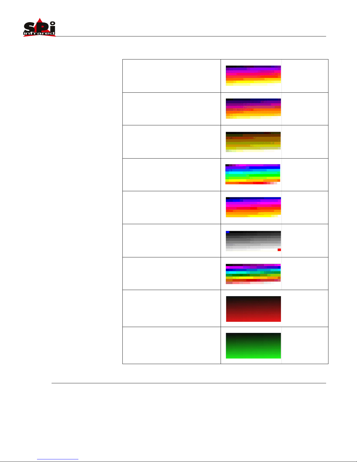
Thermal Imaging Color Palletes
The M1-D thermal imaging sensor is a full color thermal imager
capable of black and white and multiple thermal color profiles.
You can cycle through the various color profiles in the thermal
imaging sensor by pushing the IRIS CLOSE button (typically
labelled [CLOSE] on keyboard controllers). Each time you push
the [CLOSE] button the M1-D will cycle through color profiles
until you get back around to the original black and white pallete.
The following outlines the available color palletes and the order
(color palletes may change this table is for reference only).
PALLETE
DESCRIPTION
WHITE HOT
BLACK HOT
FUSION
RAINBOW
GLOWBOW
3—Basic Operation of the Tau 640 and GUI Tau 640 User’s Manual
3-18 June 2011 TAU-0640-00-10, version 110
Polarity/LUT: The Tau 640 camera detects and images the
temperatures in a given scene. Within the camera, these temperatures
are mapped (as determined by the AGC algorithm selected) to a range of
0 to 255 values. In a black and white display mode, this range is
converted to shades of grey with, for example, 0 being totally black and
255 being totally white. The 0 to 255 grayshades range sensed is
referenced to a Look-Up Table (LUT) permanently stored in the camera
to convert the scene to a video image. Different LUTs are available to
change the appearance of the displayed image. The most common
selection is either White Hot (hotter objects appear brighter than cooler
objects in the video display) or Black Hot (hotter objects appear darker
than cooler objects). Since the difference between these two modes
simply reverses the choice of darker or lighter for temperature
extremes, this is sometimes referred to as Polarity. Other color LUTs
are available as shown below.
Figure 3-7 shows each of the LUTs as displayed in Test Pattern Ramp Mode starting with the
upper left: White Hot, Black Hot, Fusion, Rainbow, Globow, Ironbow1, Ironbow2, Sepia, Color1,
Color2, Ice Fire, Rain, Red Hot, and Green Hot. Select one of these LUTs from the pull-down
menu to view your image displayed using the LUT you choose. The setting of the Polarity/LUT
mode will not affect the digital data output.
Simple experimentation with this feature while viewing the video image will give you familiarity.
Remember that you must click the Save Settings button on the Setup tab to save the LUT
settings as the default at power-up.
White Hot
Color1
Globow
Black Hot Fusion Rainbow
Ironbow1 Ironbow2 Sepia
Color2 Ice Fire Rain
Figure 3-7: Look-Up Table Options
Cold
Hot
Cold
Hot
Cold
Hot
Cold
Hot
Cold
Hot
Cold
Hot
Cold
Hot
Cold
Hot
Cold
Hot
Cold
Hot
Cold
Hot
Cold
Hot
Cold
Hot
Red Hot Green Hot
Cold
Hot
Cold
Hot
Sierra Pacific Innovations Corp 1.3.2
M1-D User’s Guide 20
IRONBOW 1
IRONBOW 2
SEPIA
COLOR 1
COLOR 2
ICE FIRE
RAIN
RED HOT
GREEN HOT
Pallette Description Table 1.4
3—Basic Operation of the Tau 640 and GUI Tau 640 User’s Manual
3-18 June 2011 TAU-0640-00-10, version 110
Polarity/LUT: The Tau 640 camera detects and images the
temperatures in a given scene. Within the camera, these temperatures
are mapped (as determined by the AGC algorithm selected) to a range of
0 to 255 values. In a black and white display mode, this range is
converted to shades of grey with, for example, 0 being totally black and
255 being totally white. The 0 to 255 grayshades range sensed is
referenced to a Look-Up Table (LUT) permanently stored in the camera
to convert the scene to a video image. Different LUTs are available to
change the appearance of the displayed image. The most common
selection is either White Hot (hotter objects appear brighter than cooler
objects in the video display) or Black Hot (hotter objects appear darker
than cooler objects). Since the difference between these two modes
simply reverses the choice of darker or lighter for temperature
extremes, this is sometimes referred to as Polarity. Other color LUTs
are available as shown below.
Figure 3-7 shows each of the LUTs as displayed in Test Pattern Ramp Mode starting with the
upper left: White Hot, Black Hot, Fusion, Rainbow, Globow, Ironbow1, Ironbow2, Sepia, Color1,
Color2, Ice Fire, Rain, Red Hot, and Green Hot. Select one of these LUTs from the pull-down
menu to view your image displayed using the LUT you choose. The setting of the Polarity/LUT
mode will not affect the digital data output.
Simple experimentation with this feature while viewing the video image will give you familiarity.
Remember that you must click the Save Settings button on the Setup tab to save the LUT
settings as the default at power-up.
White Hot
Color1
Globow
Black Hot Fusion Rainbow
Ironbow1 Ironbow2 Sepia
Color2 Ice Fire Rain
Figure 3-7: Look-Up Table Options
Cold
Hot
Cold
Hot
Cold
Hot
Cold
Hot
Cold
Hot
Cold
Hot
Cold
Hot
Cold
Hot
Cold
Hot
Cold
Hot
Cold
Hot
Cold
Hot
Cold
Hot
Red Hot Green Hot
Cold
Hot
Cold
Hot
Table of contents
Popular Security Camera manuals by other brands

Panasonic
Panasonic WV-NP240 series operating instructions

COP Security
COP Security 15-CD55TWAI Installation and operation manual

Starlight Xpress
Starlight Xpress TRIUS PRO-814C manual

Novus
Novus NVIP-4H-6202M user manual

Novus
Novus NVIP-5H-6711/TA/3 quick start guide

Seitz
Seitz Roundshot Livecam Generation 4 installation manual


Radio Shack
Radio Shack B/W 1/3-INCH BASIC CCD CAMERA owner's manual

excelPTZ
excelPTZ PTZ508 Series Installation and operation manual

3xLogic
3xLogic VX-2S-D4-RIA quick start guide

Vivotek
Vivotek IP8364-C user manual

Panasonic
Panasonic SD XC WV-SFN480 installation guide

Idis
Idis DC-V3213XJ-4.3mm quick guide