Sierra Video Pro XL Series User manual
SIERRA VIDEO
Sierra Pro XL Series 32 Routing Switchers
Models: 3232V5, 3232V4, 3232V3, 3232V2, 3216V5, 3216V4,
3216V3, 3216V2, 3232S, 3216S
User’s Manual


PRO XL SERIES 32 ROUTING SWITCHERS
User’s Manual
Sierra Video
P.O. Box 2462 Grass Valley, CA 95945
Tel: (530) 478-1000
Fax: (530) 478-1105
Version 11.0
Publication Date: September 2014
The information contained in this manual is subject to change by Sierra Video


Contents - 1
Table of
Contents
Introduction 1
Before You Begin 1
Warnings & Safety Regulations 2
Power Supply Cords 3
North American Power Supply Cords 3
International Power Supply Cords 3
EMC Regulatory Notices 3
Delivery Damage Inspection 3
Pro Series 32 Overview 4
Introduction 4
Model Suffix Designations 4
Pro Series 32 System Components 5
Series 32 6
Series 32S 7
Factors Affecting Quality of Results 8
Installation 9
Introduction 9
Rack Mounting 9
Dimensions 9
Connecting To Video Devices 10
Module Layout 10
Connecting H/V Sync 11
Balanced/Unbalanced Audio Connections 12
Audio Adjustments 12
Audio Follow Video and Breakaway Audio
Configurations 13
Connecting Peripherals 14
J1 Connector 14
Sync Input 14
AC Power Connections 15
Control Processor Dip Switch Settings 15
Serial port wiring 16
Ethernet Setup 17
Ethernet Control 19
Names 21
Salvos 21
Room Grouping 21
Matrix Mapping 21
Sync Rate Reporting 22
Operation 23
Introduction 23
Local Control Panel Operation 23
Switcher Operation 24
Button and Display Definitions 24
Menu 24
MENU TREE 25
Switching the Router 26
Switching AFV (all levels); 26
Split Switching (break-away); 27
Switching by Level; 27
Status 27
Control via 9-pin Connectors 28
Conversion to RS-422 28
Control via Ethernet 28
Serial Port Wiring 28
Host Mode 28
Terminal Mode 28
Power Up 29
Communication Protocol 31
Introduction 31
Commonly Used Switching Commands 51
Troubleshooting 53
Specifications 57
Warranty 59


SIERRA VIDEO
1
Introduction
Before You Begin
There are several terms and acronyms that you should become familiar with before reading this
manual. They are shown below.
Term/Acronym Definition
Crosspoint The electronic switch that assigns one of the inputs on the
matrix crosspoint modules to an output.
Destination The output of a routing switcher connected to a device that
receives signals from the output of the switcher.
Output Connects the signal to the destination device.
Source The signal that is connected to the input of the routing
switcher.
Input Connected to the source that provides the signal to the
switcher.
Matrix The crosspoint array of the switcher module that selects
which input is selected to an output.
Protocol The command structure used on a serial bus to effect a
switch or multiple switches on the routing switcher.
Routing Switcher Consists of one or more crosspoint modules that switch
together, or sometimes independently, to connect the
desired signals through the switcher.
Serial Port The 9-pin RS232 connector that allow you to control the
switcher using a standard personal computer or other
external device. Sends control protocol commands in
ASCII.
Chapter
1

SIERRA VIDEO
2
Warnings & Safety Regulations
The information in the following section provides important warnings and safety guidelines for
both the operator and service personnel. Specific warnings and cautions may be found
throughout this manual. Please read and follow the important safety precautions noting especially
those instructions relating to risk of fire, electrical shock and injury to persons.
Any instructions in this manual that require opening the equipment cover or enclosure are
intended for use by qualified service personnel only. To reduce the risk of electrical shock, do not
perform any servicing other than what is contained in the operating instructions unless you are
qualified.
Warnings
Heed all warnings on the unit and in the operating instructions.
Disconnect AC power before installing any options.
Do not use this product in or near water.
This product is grounded through the grounding conductor of the power cord. To
avoid electrical shock, plug the power cord into a properly wired receptacle before
connecting inputs or outputs.
Route power cords and other cables so that they are not likely to be damaged, or
create a hazard.
Dangerous voltages exist at several points in this product. To avoid personal injury,
do not touch unsafe connections and components when the power is on.
To avoid fire hazard, use only the specified type, correct voltage, and current rating
of fuse. Always refer fuse replacement to qualified service personnel.
Have qualified personnel perform safety checks after any completed service.
To reduce risk of electrical shock, be certain to plug each power supply cord into a
separate branch circuit employing a separate service ground.
If equipped with redundant power, this unit has two power cords. To reduce the risk
of electrical shock, disconnect both power cords before servicing.
Operate only with covers and enclosure panels in place – Do Not operate this
product when covers or enclosure panels are removed.
This is an FCC class A product. In a domestic environment, this product may cause
radio interference, in which case the user may be required to take necessary
measures.
Cautions
Use the proper AC voltage to supply power to the switcher. When installing
equipment, do not attach the power cord to building surfaces.
To prevent damage to equipment when replacing fuses, locate and correct trouble
that caused the fuse to blow before applying power.

Pro Series 32 XL
3
Cautions (continued)
Use only the recommended interconnect cables to connect the switcher to other
frames.
Follow static precautions at all times when handling the equipment.
Power this product only as described in the installation section of this manual.
Leave the side, top, and bottom of the frame clear for air convection cooling and to
allow room for cabling. Slot and openings in the frame are provided for ventilation
and should not be blocked.
Only an authorized Sierra Video technician should service the switchers. Any user
who makes changes or modifications to the unit without the expressed approval of
Sierra Video will void the warranty.
If installed in a closed or multi-unit rack assembly, the operating ambient
temperature of the rack environment may be greater than the room ambient
temperature. Therefore, consideration should be given to installing the equipment in
an environment compatible with the manufacturer’s maximum rated ambient
temperature (TMRA).
Installation of the equipment in a rack should be such that the amount of air flow
required for safe operation of the equipment is not compromised.
Power Supply Cords
North American Power Supply Cords
This equipment is supplied with North American power cords with molded grounded plug (NEMA-
15P) at one end and molded grounding connector (IEC 320-C13) at the other end. Conductors
are CEE color coded, light blue(neutral), brown(line), and green/yellow(ground). Operation of the
equipment at voltages exceeding 130VAC will require power supply cords that comply with NEMA
configurations.
International Power Supply Cords
If shipped outside North America, this equipment is supplied with molded ground connector (IEC
320-C13) at one end and stripped connectors (50/5mm) at the other end. Connections are CEE
color coded, light blue (neutral), brown (line), and green/yellow (ground). Other IEC 320-C13 type
power cords can be used if they comply with safety regulations of the country in which they are
installed.
EMC Regulatory Notices
Federal Communications Commission (FCC) Part 15 Information: This device complies with Part
15 of the FCC standard rules. Operation is subject to the following conditions:
This device may not cause harmful interference
This device must accept any interference received including interference that may cause
undesirable operations.
Delivery Damage Inspection
Carefully inspect the frame and exterior components to be sure that there has been no shipping
damage. Make sure all modules are seated correctly and have not detached during shipment.
SIERRA VIDEO
4
Pro Series 32 Overview
Introduction
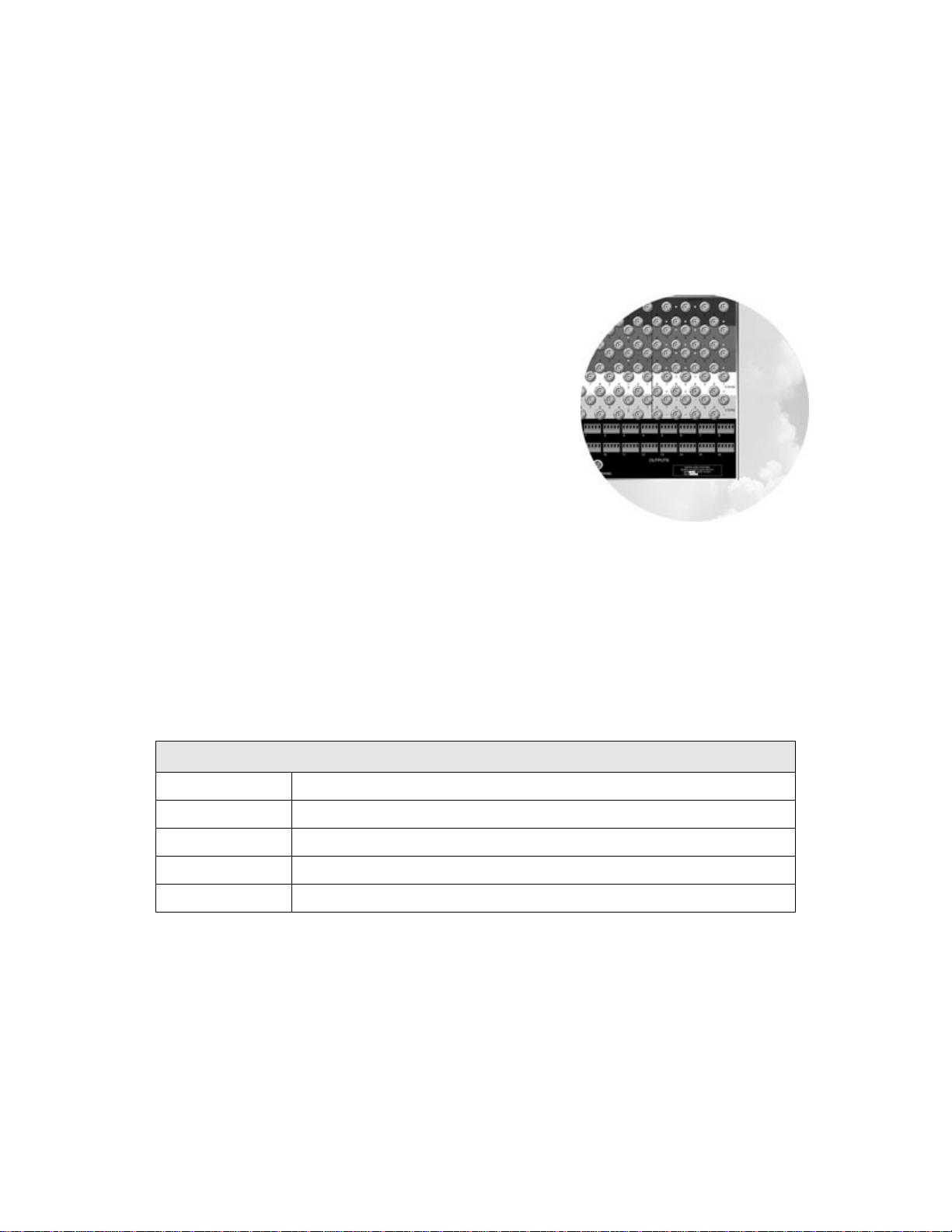
The SV Pro series Family of component analog routing switchers offers high-bandwidth 2, 3, 4, or
5 channel (RGB + HV) in a single frame. With stereo audio (S) matrix routing capability in a
separate frame. The Pro series was designed specifically for presentation environments such as
corporate boardrooms, live staging events, churches, and
universities.
This manual covers only the Pro Series 32 routing
switchers. These robust routers offer RGB/HV and Stereo
Audio in separate frames. Moreover, these durable video
frames can be populated from one to five video and pulse
sync channels. They have been engineered for high
bandwidth with very low crosstalk. Many other features
include audio gain adjustment for Inputs and Outputs
through standard front control panels or via a control
serial port and optional redundancy. The series 32 system
accommodates balanced or un-balanced audio, AFV, or
breakaway split routing allowing RGB muting for
seamless performance to projectors and displays. This
family of routing switchers is optimized for multiple signal type control within the same frame.
Composite, S-video, YC, YUV, RGBHV, and audio are easily controlled. The Pro Series 400MHz
bandwidth supports most high-resolution sources.
The Pro Series 32 models also feature a user-friendly, color-coded (RGB) rear panel layout for
easy installation, and their own unique motherboard configuration options. Frames also come
with standard front local control and serial control via an RS-232 serial interface that is supported
by SV TyLinx Pro software and by all major third-party control systems. An extensive line of
existing XY or single-bus remote control panels is also available.
Model Suffix Designations
Model Suffix Designations
V Analog video (450MHz bandwidth)
3232,3216 Matrix size
# Number of video and sync channels (analog, YC, RGB, RGB+HV etc.)
S Stereo audio
R Redundant Power Supplies

Pro Series 32 XL
5
Pro Series 32 System Components
This User’s Manual provides installation and operation information for the Pro Series 32 Routing
Switchers. Front and Rear panel illustrations are provided in the following subsections for each
switcher model. Take time to familiarize yourself with the location of your switcher model features.
Component Pro Series 32 Switchers
3232V5 3232S, 3216S
Frame Video contained in one
frame
Power Supply(ies)
Video Motherboard
Video Modules
Sync Modules*
Local Control Panel
Audio contained in one
frame
Power Supply(ies)
Audio Motherboard
Audio Modules
Accessory Kit User’s Manual
Fuses
Power Cord(s)
Software Disk
User’s Manual
5-pin Audio Connectors
Fuses
Power Cord(s)
* Optional on V4, V3, V2 (V5 may contain all Video Modules, if ordered)

SIERRA VIDEO
6
Series 32
Video Frame Front Panel
Video Frame Back Panel

Pro Series 32 XL
7
Series 32S
Audio Frame Front Panel
Audio Frame Back Panel
Earth Ground Connection
Note
The models shown are fully populated video
and audio matrices. In some cases frames
may be configured with fewer or no video
and audio channels i.e. 3216S or 3232V3.
The models shown here have the redundant
power option.
The system you receive is customized for
the size & type requested at time of
purchase.
Ground
Connection
8-32 Thread

SIERRA VIDEO
8
Factors Affecting Quality of Results
There are many factors affecting the quality of results when signals are transmitted from a source
to a destination.Signal cables — Use only the best quality cables to avoid interference and
degraded signal quality and elevated noise levels.
Sockets and connectors of the sources and destinations — Use only the highest
quality, since “zero ohm” connection resistance is the target. Connectors should
also match the required impedance (75 ohm in video) to minimize return loss.
Amplifying circuitry — Must have quality performance when the desired end
result is high linearity, low distortion, and low noise.
Distance between sources and destinations — Plays a major role in the final
result. For long distances (over 15 meters) between sources and destinations,
special measures should be taken to avoid high frequency cable losses. These
measures include using higher quality cables and/or adding line cable equalizing
amplifiers.
Interference from neighboring electrical appliances — These can have an
adverse affect on signal quality. Balanced audio lines are less prone to
interference, but unbalanced audio should be installed away from any main
power lines, electric motors, transmitters, etc. even when the cables are shielded.
CAUTION!
Only an authorized Sierra Video technician can service the switchers. Any user who makes
changes or modifications to the unit without the expressed approval of the manufacturer will void
the warranty
Use the proper AC voltage to supply power to the switcher.
Use only the recommended interconnect cables to connect the switcher to other frames.

SIERRA VIDEO
9
Installation
Introduction
Installation procedures are similar for all frames covered under this manual. Exceptions, if any,
have been noted in each of the following paragraphs.
Rack Mounting
Carefully inspect the frame to ensure that there has been no shipping damage. Make sure all
shipping material is removed from the router frame.
Each of the routing switchers described in this manual can be rack mounted in a standard 19”
(RU) EIA rack assembly and includes rack “ears” at the ends of the front of the frames. None of
the switcher models require spacing above or below the unit for ventilation. If ample space exists,
a 1RU spacing gap is recommended.
To rack mount any of the routing switchers, simply place the unit’s rack ears against the rack rails
of the rack, and insert proper rack screws through each of the holes in the rack ears. Always rack
mount the routing switcher prior to plugging the unit into a power receptacle or attaching any
cables.
CAUTION!
The operating temperature range of the SV 32 series router is 0 to 40 °C. Do not exceed the maximum
(40 °C) or minimum (0 °C) operating temperature.
If installed in a closed or multi-unit rack assembly, the operating ambient temperature of the rack
environment may be greater than the room ambient temperature. Therefore, consideration should
be given to installing the equipment in an environment compatible with the manufacturer’s
maximum rated ambient temperature (TMRA).
Installation of the equipment in a rack should be such that the amount of air flow required for safe
operation of the equipment is not compromised.
Dimensions
The Pro Series 32 video frames are 9 rack units in height, 19” wide, and 16.5” in depth.
The Audio frames are 3 rack units in height, 19” wide, and 17” in depth.
Chapter
2
SIERRA VIDEO
10
Connecting To Video Devices
Video sources and output devices (such as monitors, or recorders) may be connected to the
routing switchers through the BNC type connectors located on the back of the unit. Keep in mind
that the output signal format will be that of the input signal format.
All signal connections that use more than one cable interconnecting between devices should be
of equal timing length (example: cables between a camera and the switcher should have the
same time delay).
The rear panel of the frame is laid out in the most logical fashion possible. The individual
channels are color-coded. The white and yellow conventions, used for the H and V sync
channels, are arbitrary and these two channels are interchangeable. Each channel can have only
“H” or “V” signals – not both. All inputs are factory set for 510 ohm termination.
The sync (“H” “V”) input terminations can be changed to 75 via software using “G” commands,
front panel Menu, or the TyLinx Pro software (see the TyLinx Pro manual for details).
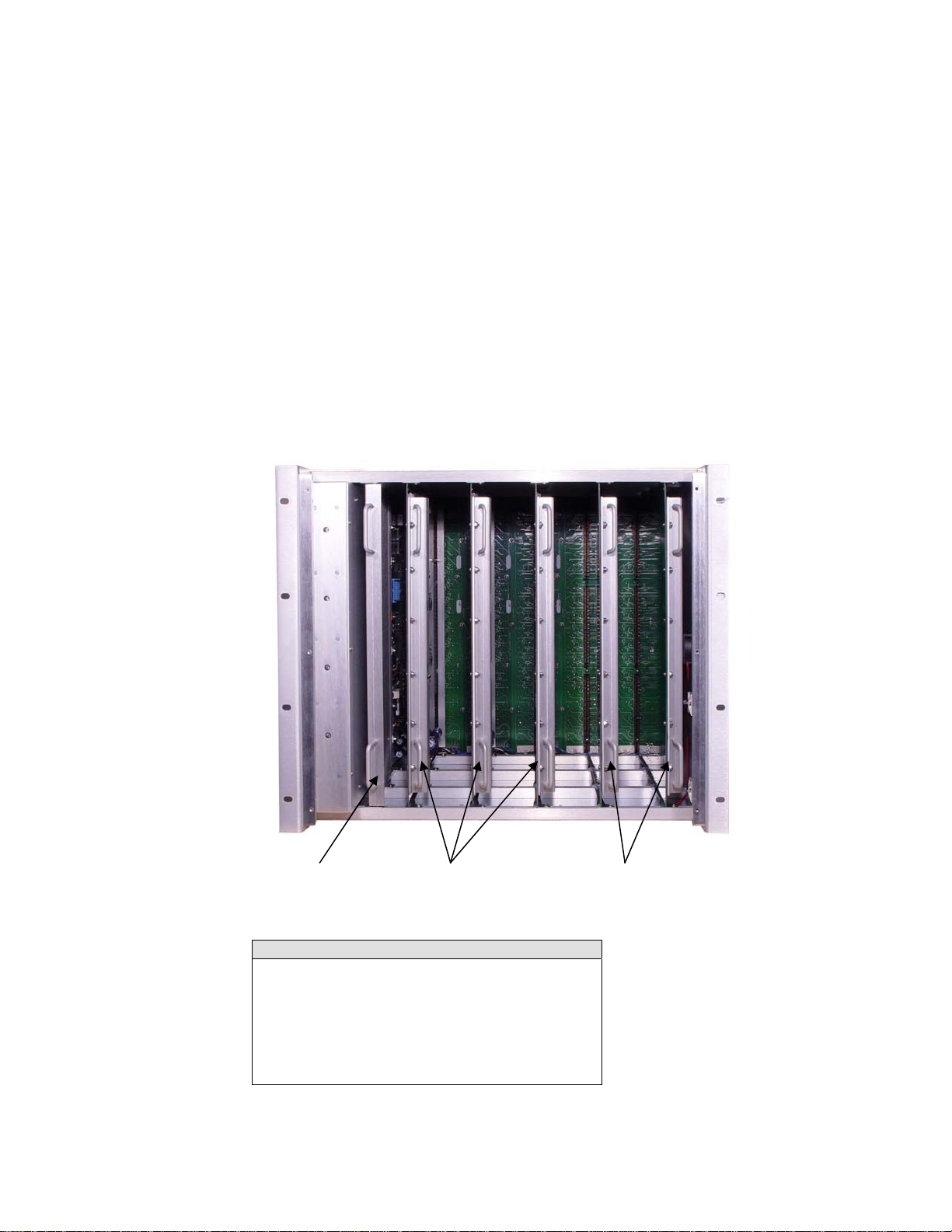
Module Layout
Note
The model shown is a fully populated video
(V3 + 2 sync) matrix. In some cases frames
may be configured with fewer or all video
channels i.e. 3232V2 or 3232V3.
The system you receive is customized for
the size & type requested at time of
purchase.
Processor
Module Video
Modules Sync
Modules
INSTALLATION
11
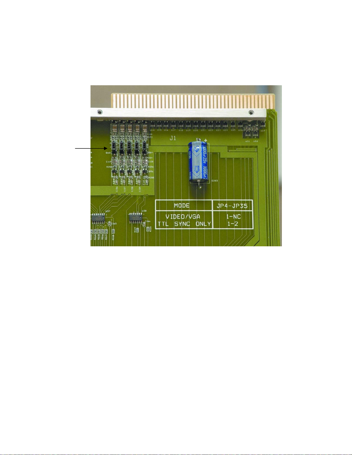
Connecting H/V Sync
There are two types of sync signals supported in the SV system. The most common type is
300mv to 5v p-p. The factory default is set to accept this type of sync.
The second sync setting allows for high frequency TTL sync signals. If you are experiencing jitter,
move the jumper on the Horizontal sync module to this setting.
Some models do not have Video/VGA and TTL sync jumpers. Boards that do not have jumpers
are auto sensing to the input(s) sync type.
Sync
Jummpers

SIERRA VIDEO
12
Connecting To Audio Devices
Audio sources and output devices (such as amplifiers or recorders) are connected to the
switchers through the terminal block connectors located at, and marked, on the rear of the
switcher.
Balanced/Unbalanced Audio Connections
All audio sources from the routing switcher are balanced audio. Connect the balanced audio to
the balanced input of your destination device(s).
If this is a 2-channel system used for stereo audio, ensure that you keep the same phase
relationship. Connect the positive designated pin to the same relative pin on the destination
device of both channels.
To connect an unbalanced device to the switcher, first place a jumper between the negative (-)
and the ground on the switcher (jumper not included.) Then connect the device positive (+) to
positive (+) and shield to ground as shown in the graphic below.
For unbalanced sources, connect the unbalanced source to one side of the balanced input and
ground. The other input does not have to be grounded. Note, always use the same side of the
balanced input for stereo.
Audio Adjustments
Unity gain is set at the factory. Audio gain is adjusted via a menu option. See “Menu Items” in the
Operation section Chapter 3. Audio gains may also be adjusted via the 9 pin serial port using the
Video Frame
Optional Audio Frame
J1
J1
25 Pin- J1 frame interconnect cable
1616V5S Terminal block connectors

INSTALLATION
13
TyLinx Pro Software program (refer to the TyLinx Pro manual), or using Host protocol (see
Communication protocol Ch. 4).
Audio Follow Video and Breakaway Audio Configurations
Component video channel (YC, RGB etc.) signals are switched by separate crosspoint modules.
All crosspoint modules will be switched at the same time. Audio can be switched following the
video or separately after the breakaway.
SIERRA VIDEO
14
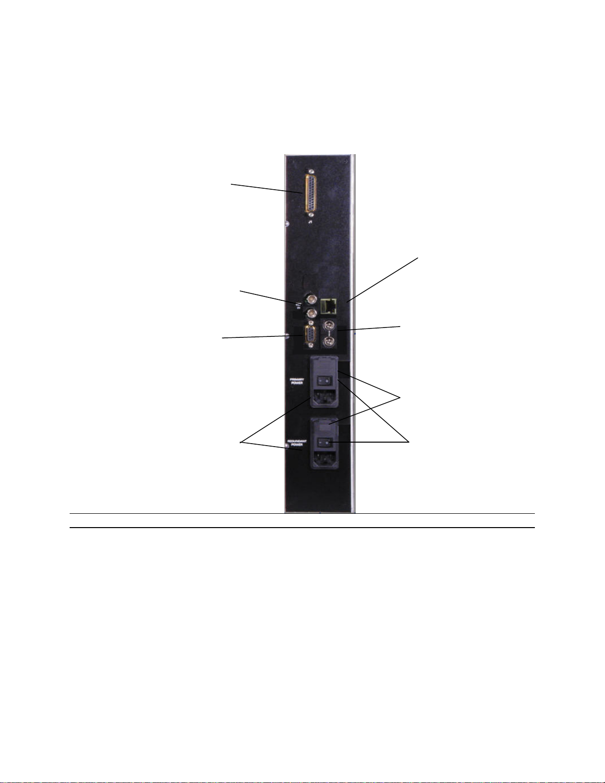
Connecting Peripherals
Control panels, sync inputs, and power are all connected to the rear of the frame. The peripherals
area may vary depending on the model size and type.
SV Pro series 32 routing switchers offer redundant power supplies.
Note:
Rear Panels vary according to model. See back panel for precise detail.
J1 Connector
The connector labeled J1 on the back panel is used to connect other routing devices to the
router. Contact the factory for correct configuration before connecting other devices.
Sync Input
There are two BNC connectors labeled “VID. REF. IN”. This is a “looping” input for sync
referencing. Connect either composite sync or video with sync to either BNC. If desired, use the
second BNC to loop the signal to another device. If the loop is not used, terminate the second
BNC with 75 ohms. If no sync is available, the routing switcher will switch at a random point
rather than during the vertical interval of the reference signal.
V
ideo Sync
Referencing
Inputs
RS-232 and RS-
422 control
connector
Control Panel
Connectors
Fuses
Power Switch
AC Power
Connection
J-1 Multi-Frame
co
nn
ector
Ethernet
Connector
This manual suits for next models
10
Table of contents
Other Sierra Video Switch manuals


Popular Switch manuals by other brands

ATEN
ATEN CS782DP quick start guide

Rose electronics
Rose electronics SuperSwitch SS-9 features and benefits

Extron electronics
Extron electronics DTP2 T 204 user guide

StarTech.com
StarTech.com U01043-USB-EXTENDER quick start guide

Intel
Intel Hubs and Switches Quick setup guide

TRENDnet
TRENDnet TEG-S811Fi Quick installation guide


