manuals.online logo
Brands
  1. Home
  2. •
  3. Brands
  4. •
  5. ADTRAN
  6. •
  7. Switch
  8. •
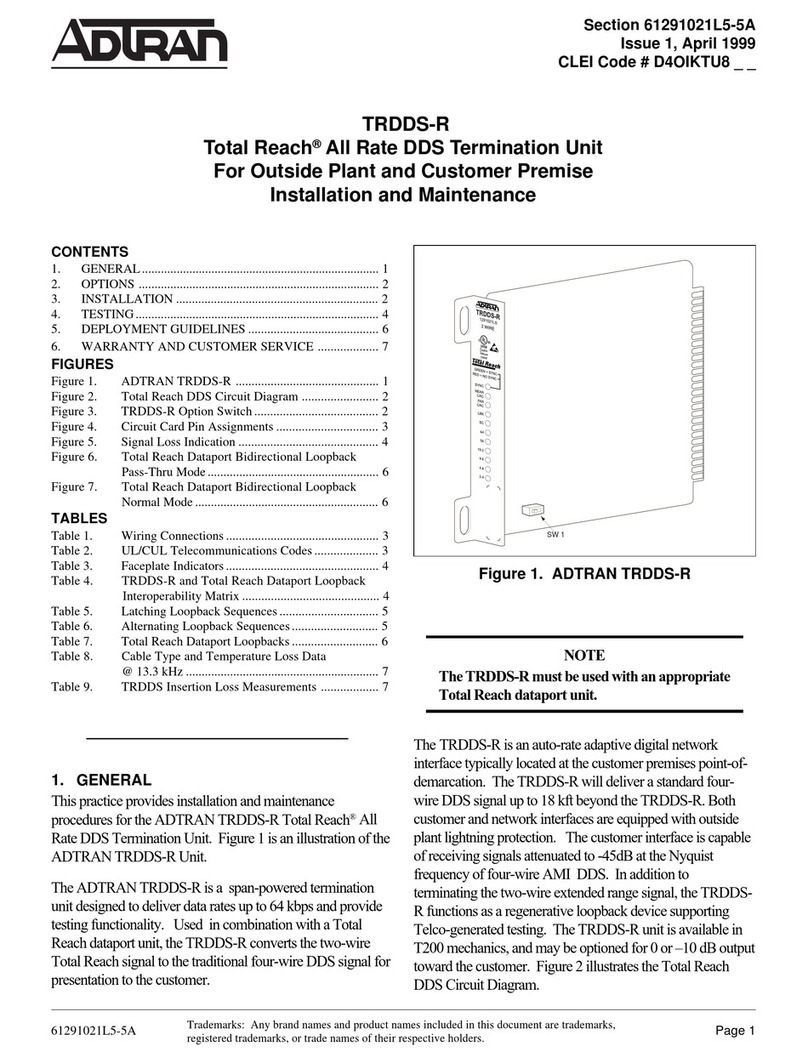
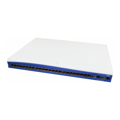
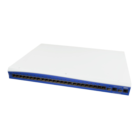
  9. ADTRAN NetVanta 1748F Series User manual

ADTRAN NetVanta 1748F Series User manual

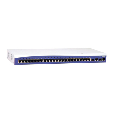
1. Unpack the Switch and Check Contents
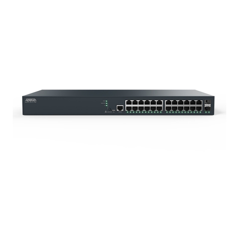
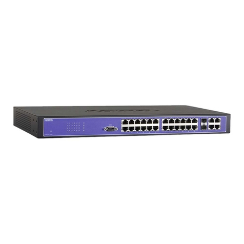
NetVanta 1748F
Rack Mounting Kit—Contains two brackets and eight
screws for attaching the brackets to the switch.
Power Cord
Console Cable—RJ-45 to DB-9
Documentation—Quick Start Guide
2. Mount the Switch
Attach the brackets to the switch.
Use the screws supplied with the rack to secure the switch in
the rack.
2
1
1
2
4. Connect Power
The switch is shipped with two universal AC power modules
installed.
Connect an external AC power source to the modules.
1
2
1
2
5. Verify Switch Operation
Verify basic switch operation by checking the system LEDs.
When operating normally, the PSU1/PSU2, Diag, and Fan
LEDs should all be on green.
1
1
–1–61700558F1MC-13A
January 2016
Support - Phone: 888-423-8726
Copyright © 2016 ADTRAN, Inc. All Rights Reserved.
NetVanta 1748F
1700558F1#MC
6. Perform Initial Conguration
At this point you may need to make a few basic switch
conguration changes before connecting to the network.
Connect a PC to the switch console port using the included
console cable.
Congure the PC’s serial port: 115200 bps, 8 characters, no
parity, one stop bit, 8 data bits, and no ow control.
Log in to the command-line interface (CLI) using default
settings: User “admin” with no password.
3
1
2
1
2
3
Hardware Specications
Chassis Specications
Size 438.4-mm W x 473-mm D x 43.4-mm H
17.26-inch W x 18.62-inch D x 1.71-inch H
Weight
Temperature
Humidity
Power Supply Specications
AC Input
DC Output 5 VDC at 3 A
12 VDC at 33 A
Power Supply
Power
Consumption
165 W maximum
Maximum
Current
6 A at 100 VAC
3 A at 240 VAC
Size54.5-mm W x 220-mm D x 40.25-mm H
(2.15-inch W x 8.66-inch D x 1.58-inch H)
Regulatory Compliances
Emissions EN 55022:2010 Class A
EN 61000-3-2:2009 Class A
EN 61000-3-3:2008
FCC Class A
VCCI Class A
CE Mark
Immunity
Safety
EN 55024:2010
ICE 61000-4-2/3/4/5/6/8/11
UL (CSA 22.2 No 60950-1 and UL 60950-1)
CB (IEC/EN 60950-1)
8.395 kg (18.51 lb), with two installed power supply
modules
Operating: 0°C to 40°C (32°F to 104°F)
Storage: -40°C to 70°C (-40°F to 158°F)
Operating: Up to 95percent, noncondensing
100 to 240 VAC, 50/60 Hz
100 to 240 VAC, 50/60 Hz, auto-sensing; hot pluggable
400 W at 240 V/100 V per module
NetVanta 1748F
1700558F1#MC
–2–61700558F1MC-13A
January 2016
Support - Phone: 888-423-8726
Copyright © 2016 ADTRAN, Inc. All Rights Reserved.
Safety and Regulatory Information
FCC Class A
This equipment has been tested and found to comply with the limits for
a Class A digital device, pursuant to part 15 of the FCC Rules. These limits
are designed to provide reasonable protection against harmful
interference when the equipment is operated in a commercial
environment. This equipment generates, uses, and can radiate radio
frequency energy and, if not installed and used in accordance with the
instruction manual, may cause harmful interference to radio
communications. Operation of this equipment in a residential area is
likely to cause harmful interference in which case the user will be
required to correct the interference at his own expense.
You are cautioned that changes or modications not expressly approved
by the party responsible for compliance could void your authority to
operate the equipment.
You may use unshielded twisted-pair (UTP) for RJ-45 connections,
Category 3 or better for 10 Mbps connections, Category 5 or better for
100 Mbps connections, Category 5, 5e, or 6 for 1000 Mbps connections.
For ber optic connections, you may use 50/125 or 62.5/125 micron
multimode ber or 9/125 micron single-mode ber.
Laser Safety
Warning:
Fiber Optic Port Safety: Class A Laser Device
When using a ber optic port, never look at the transmit laser while it is
powered on. Also, never look directly at the ber TX port and ber cable
ends when they are powered on.
Power Cord Safety
Please read the following safety information carefully before installing
the unit:
Warning:
• Installation and removal of the unit must be carried out by qualied
personnel only.
• The unit must be connected to an earthed (grounded) outlet
to comply with international safety standards.
• Do not connect the unit to an AC outlet (power supply) without an
earth (ground) connection.
• The appliance coupler (the connector to the unit and not the wall
plug) must have a conguration for mating with an EN 60320/IEC 320
appliance inlet.
• The socket outlet must be near to the unit and easily accessible. You
can only remove power from the unit by disconnecting the power
cord from the outlet.
• This unit operates under SELV (Safety Extra Low Voltage) conditions
according to UL 60950-1. The conditions are only maintained if the
equipment to which it is connected also operates under SELV
conditions.
Power Cord Set
The cord set must be UL-approved.
The minimum specications for the exible cord are:
- No. 18 AWG - not longer than 2 meters or 16 AWG
- Type SV or SJ
- 3-conductor
The cord set must have a rated current capacity of at least 10 A.
The attachment plug must be an earth-grounding type with NEMA
5-1SP (15 A, 125 V) conguration.
Warnings and Cautionary Messages
Warning:
• This product contains no user serviceable parts.
• Installation and removal of the unit must be carried out by
qualied personnel only.
• When connecting this device to a power outlet, connect the eld
ground lead on the tri-pole power plug to a valid earth ground line
to prevent electrical hazards.
• This switch uses lasers to transmit signals over ber optic cable.
The lasers are compliant with the requirements of a Class 1 Laser
Product and are inherently eye safe in normal operation. However,
you should never look directly at a transmit port when it is
powered on.
• When selecting a ber SFP/SFP+/QSFP+ device, considering safety,
make sure that it can function at a temperature that is not more
than the recommended maximum operational temperature of the
product. You must also use an approved Laser Class 1
SFP/SFP+/QSFP+ transceiver.
Caution:
• Wear an anti-static wrist strap or take other suitable measures to
prevent electrostatic discharge when handling this equipment.
• Do not plug a phone jack connector in the RJ-45 port. This may
damage this device.
• Use only twisted-pair cables with RJ-45 connectors that conform to
FCC standards.
• The switch includes plug-in power supply and fan tray modules
that are installed into its chassis. All installed modules must have a
matching airow direction. That is, all modules must have a
front-to-back (F2B) airow direction, or all modules must have a
back-to-front (B2F) airow direction. The airow direction of PSUs
and fan trays is indicated by labels on the modules.
• Installing the switch in a rack requires two people: one should
position the switch in the rack, while the other secures it using the
mounting screws.
Other manuals for NetVanta 1748F Series

1

This manual suits for next models

2

Other ADTRAN Switch manuals

ADTRAN Hub Instruction Manual

ADTRAN

ADTRAN Hub Instruction Manual

ADTRAN NetVanta 1524ST User manual

ADTRAN

ADTRAN NetVanta 1524ST User manual

ADTRAN NetVanta 1560-08-150W User manual

ADTRAN

ADTRAN NetVanta 1560-08-150W User manual

ADTRAN NetVanta 1224 User manual

ADTRAN

ADTRAN NetVanta 1224 User manual

ADTRAN NetVanta 1560-24-370W User manual

ADTRAN

ADTRAN NetVanta 1560-24-370W User manual

ADTRAN SDX 8110-24-740W User manual

ADTRAN

ADTRAN SDX 8110-24-740W User manual

ADTRAN netvanta 1230 series User manual

ADTRAN

ADTRAN netvanta 1230 series User manual

ADTRAN T1-FT1 Rackmounted DSU/CSU TDU 110DC User manual

ADTRAN

ADTRAN T1-FT1 Rackmounted DSU/CSU TDU 110DC User manual

ADTRAN D4 OCU DP (ETR) D4-OCU Instruction Manual

ADTRAN

ADTRAN D4 OCU DP (ETR) D4-OCU Instruction Manual

ADTRAN FT1 DP User manual

ADTRAN

ADTRAN FT1 DP User manual

ADTRAN NetVanta 1531P User manual

ADTRAN

ADTRAN NetVanta 1531P User manual

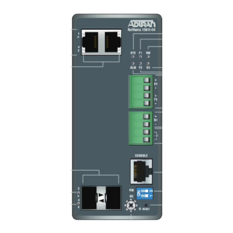
ADTRAN NetVanta 1561i-04 User manual

ADTRAN

ADTRAN NetVanta 1561i-04 User manual

ADTRAN NetVanta 1235P User manual

ADTRAN

ADTRAN NetVanta 1235P User manual

ADTRAN NetVanta 1748F Series Manual

ADTRAN

ADTRAN NetVanta 1748F Series Manual

ADTRAN NetVanta 1234 User manual

ADTRAN

ADTRAN NetVanta 1234 User manual

ADTRAN NetVanta 1224ST User manual

ADTRAN

ADTRAN NetVanta 1224ST User manual

ADTRAN NetVanta 1224 PoE User manual

ADTRAN

ADTRAN NetVanta 1224 PoE User manual

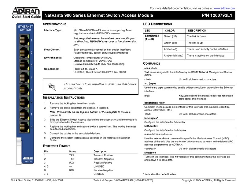
ADTRAN 600 Series User manual

ADTRAN

ADTRAN 600 Series User manual

ADTRAN NetVanta 1224ST Owner's manual

ADTRAN

ADTRAN NetVanta 1224ST Owner's manual

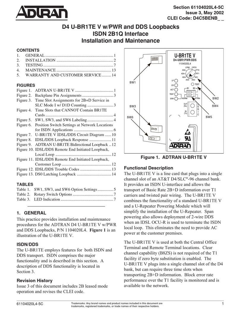
ADTRAN D4 U-BR1TE V Product manual

ADTRAN

ADTRAN D4 U-BR1TE V Product manual

ADTRAN E220 HFAC HDSL2 Instruction Manual

ADTRAN

ADTRAN E220 HFAC HDSL2 Instruction Manual

ADTRAN NetVanta 1560-48-370W User manual

ADTRAN

ADTRAN NetVanta 1560-48-370W User manual

ADTRAN 2FXS/DPO PM Product manual

ADTRAN

ADTRAN 2FXS/DPO PM Product manual

ADTRAN NetVanta 1224STR PWR Manual

ADTRAN

ADTRAN NetVanta 1224STR PWR Manual

Popular Switch manuals by other brands

Belkin F1DS102Jea Quick installation guide

Belkin

Belkin F1DS102Jea Quick installation guide

Captron SENSORswitch CHT3-F Series Configuration

Captron

Captron SENSORswitch CHT3-F Series Configuration

Siemens 3VA51 Series manual

Siemens

Siemens 3VA51 Series manual

Gems PS61P Series Instruction bulletin

Gems

Gems PS61P Series Instruction bulletin

Meltric DS Decontactor Series operating instructions

Meltric

Meltric DS Decontactor Series operating instructions

Digitus DS-12874 Quick installation guide

Digitus

Digitus DS-12874 Quick installation guide

Endress+Hauser Liquiphant M FTL50 operating instructions

Endress+Hauser

Endress+Hauser Liquiphant M FTL50 operating instructions

ATEN CS1792 user manual

ATEN

ATEN CS1792 user manual

IOGear MiniView GCS1772 user manual

IOGear

IOGear MiniView GCS1772 user manual

Siemens SIRIUS 3SE2283 GA4 Series operating instructions

Siemens

Siemens SIRIUS 3SE2283 GA4 Series operating instructions

TRENDnet TE100-S24D Specifications

TRENDnet

TRENDnet TE100-S24D Specifications

Contemporary Control Systems EISK8-100F Series installation guide

Contemporary Control Systems

Contemporary Control Systems EISK8-100F Series installation guide

H3C S5510 Series Command manual

H3C

H3C S5510 Series Command manual

Fracarro MULTISWITCH SWI504SA operating instructions

Fracarro

Fracarro MULTISWITCH SWI504SA operating instructions

Stahl 8074/2-1-DS-40 operating instructions

Stahl

Stahl 8074/2-1-DS-40 operating instructions

Action Star PK-2UA0-A-EL user manual

Action Star

Action Star PK-2UA0-A-EL user manual

GearMo GM-HU34CA-DW user manual

GearMo

GearMo GM-HU34CA-DW user manual

Extron electronics MTPX Plus Series user manual

Extron electronics

Extron electronics MTPX Plus Series user manual

manuals.online logo
manuals.online logoBrands
  • About & Mission
  • Contact us
  • Privacy Policy
  • Terms and Conditions

Copyright 2025 Manuals.Online. All Rights Reserved.