SIFCO ASC TechnoPlate Power Pack 6015A20V User manual

SIFCOTechnoPlate Power Pack_2019-05-06_V1.5_e.doc 1/68
Strictly confidential! No unauthorized circulation of content.
© All rights reserved by plating electronic GmbH. Modification and reproduction only by authorized persons!
Documentation type: Operating manual
Author: J. Schumann
Last modification by: Johannes Schumann Print date: 2019-06-28
Last saving date: 2019-06-28
Last modification: ..\History_SIFCO TechnoPlate_001.xlsx V1.5
Comment:
plating electronic GmbH - Rheinstraße 4 - D-79350 Sexau - Germany
Tel.: +49 (0)7641 / 93500-0 - Fax.: +49 (0) 7641 / 93500-999 E-Mail: info@plating.de
Operating Manual for
SIFCO ASC TechnoPlate Power Pack
with detachable control unit
Read this operating manual completely before installation.
Not following installation and operation procedures will void the warranty. It also
could result in serious injury or death.

SIFCOTechnoPlate Power Pack_2019-05-06_V1.5_e.doc 2/68
plating electronic GmbH - Rheinstraße 4 - D-79350 Sexau - Germany
Tel.: +49 (0)7641 / 93500-0 - Fax.: +49 (0) 7641 / 93500-999 E-Mail: info@plating.de

SIFCOTechnoPlate Power Pack_2019-05-06_V1.5_e.doc 3/68
plating electronic GmbH - Rheinstraße 4 - D-79350 Sexau - Germany
Tel.: +49 (0)7641 / 93500-0 - Fax.: +49 (0) 7641 / 93500-999 E-Mail: info@plating.de
List of Contents:
1EU declaration of conformity ----------------------------------------------------------------- 5
2General security information ----------------------------------------------------------------- 6
2.1 Class-A device---------------------------------------------------------------------- 6
2.2 Security ------------------------------------------------------------------------------- 6
2.3 Installation of the DC power supply modules-------------------------------- 8
2.4 Operation conditions--------------------------------------------------------------- 8
3After transportation ----------------------------------------------------------------------------- 9
3.1 Transportation locking devices-------------------------------------------------- 9
4Storage -------------------------------------------------------------------------------------------- 9
4.1 Environmental conditions for storage------------------------------------------ 9
5General description----------------------------------------------------------------------------10
5.1 Two housing sizes ----------------------------------------------------------------10
5.2 Switch mode technology---------------------------------------------------------11
5.3 Intended purpose------------------------------------------------------------------11
6Detachable control unit -----------------------------------------------------------------------12
6.1 Assembling after transportation------------------------------------------------12
6.2 Transport lock for the control unit ---------------------------------------------13
6.3 Protective cover--------------------------------------------------------------------14
6.4 Control unit with stand -----------------------------------------------------------15
7Devices 15 A / 20 V and 30 A / 20 V------------------------------------------------------16
8DC-output connection-------------------------------------------------------------------------17
9The RS485 BUS connection ----------------------------------------------------------------18
9.1 Bus - terminator--------------------------------------------------------------------19
9.2 Specification of the BUS cable-------------------------------------------------19
10 Mains supply ------------------------------------------------------------------------------------20
10.1 single-phase devices-------------------------------------------------------------20
10.1.1 Power cord plug single-phase type -------------------------------------------21
10.1.2 PFC technology--------------------------------------------------------------------21
10.2 3~phase devices ------------------------------------------------------------------22
10.2.1 Power cord plug three-phase type --------------------------------------------22
11 Back plane---------------------------------------------------------------------------------------24
12 Operation ----------------------------------------------------------------------------------------25
12.1 Main switch -------------------------------------------------------------------------25
13 Function overview of the software ---------------------------------------------------------26
14 Manual pole changer--------------------------------------------------------------------------26
15 Ampere-Hour Counter and Reset function-----------------------------------------------27
15.1 A/H value setting (A/H PRESET)----------------------------------------------27
15.2 A/H RESET function--------------------------------------------------------------27
16 Potentiometer control and step function--------------------------------------------------28
17 Potentiometers control for voltage and current -----------------------------------------29
17.1 Control function--------------------------------------------------------------------30
17.1.1 Function 1 “Counting” ------------------------------------------------------------31
17.1.2 Function 2 “Jumping” -------------------------------------------------------------32
17.1.3 Function 3 “Counting and Jumping” ------------------------------------------33
17.1.4 Function 4 “Digit reset”-----------------------------------------------------------34
18 Step function ------------------------------------------------------------------------------------35
18.1 STEP and NEXT STEP keys---------------------------------------------------36
18.2 STORE key -------------------------------------------------------------------------37
18.3 STEP RESET key-----------------------------------------------------------------37

SIFCOTechnoPlate Power Pack_2019-05-06_V1.5_e.doc 4/68
plating electronic GmbH - Rheinstraße 4 - D-79350 Sexau - Germany
Tel.: +49 (0)7641 / 93500-0 - Fax.: +49 (0) 7641 / 93500-999 E-Mail: info@plating.de
18.4 LABEL key --------------------------------------------------------------------------38
18.5 Creating a preset at STEP 1----------------------------------------------------40
19 Examples how to adjust set values--------------------------------------------------------42
19.1 Example 1: Adjust voltage set value to 24 V -------------------------------42
19.2 Example 2: Adjust voltage set value to 24.53 V ---------------------------43
19.3 Adjust existing preset values and store new values ----------------------44
19.4 Adjust preset value temporary -------------------------------------------------44
20 Settings in main menu ------------------------------------------------------------------------45
20.1 General description ---------------------------------------------------------------45
20.2 The SETTINGS functions -------------------------------------------------------46
20.3 Configuration of BUS interface-------------------------------------------------47
20.4 Total counter------------------------------------------------------------------------49
20.5 Preset counter----------------------------------------------------------------------50
20.5.1 Configuration of the preset counter -------------------------------------------51
20.6 Pole changer -----------------------------------------------------------------------54
20.6.1 Configuration of the pole changer---------------------------------------------54
20.7 Overload detection----------------------------------------------------------------56
20.7.1 Configuration of the Overload detection -------------------------------------57
20.8 The STEP menu-------------------------------------------------------------------58
20.9 Set label -----------------------------------------------------------------------------58
21 Technical data ----------------------------------------------------------------------------------59
21.1 General specifications------------------------------------------------------------59
21.2 Individual specifications----------------------------------------------------------60
21.2.1 Type 6015A20V--------------------------------------------------------------------60
21.2.2 Type 6030A20V--------------------------------------------------------------------60
21.2.3 Type 6015A50V--------------------------------------------------------------------60
21.2.4 Type 6060A20V--------------------------------------------------------------------61
21.2.5 Type 3750 W -1 coming year 2020 ------------------------------------------61
21.2.6 Type 3750 W -2 coming year 2020 ------------------------------------------61
22 Dimensions--------------------------------------------------------------------------------------62
23 Checking calibration---------------------------------------------------------------------------65
23.1 Voltage calibration ----------------------------------------------------------------65
23.2 Current calibration-----------------------------------------------------------------66
24 Service and maintenance--------------------------------------------------------------------67
25 Spare parts list----------------------------------------------------------------------------------68
26 Warranty and Repair Information ----------------------------------------------------------68
Packing list:
- Rectifier unit “SIFCO ASC TechnoPlate” (type: see
package labeling, and rating plate)
- Control unit SIFCO ASC (for type 15A / 20 V and 30 A / 20 V: integrated
control panel)
- Three types of mains power cord (individual plugs) for
single-phase devices
- Operating manual

SIFCOTechnoPlate Power Pack_2019-05-06_V1.5_e.doc 5/68
plating electronic GmbH - Rheinstraße 4 - D-79350 Sexau - Germany
Tel.: +49 (0)7641 / 93500-0 - Fax.: +49 (0) 7641 / 93500-999 E-Mail: info@plating.de
1 EU declaration of conformity
Conformity declaration of the European community corresponding to the EMV-
guidelines 2014/30/EU about the electromagnetic compatibility and the low-voltage
guidelines 2014/35/EU.
We
Manufacturer: plating electronic GmbH
Ust.-Id No.: DE 141938869
Address: Rheinstraße 4
79350 Sexau / Deutschland
declare that the product, listed below, is corresponding to the following standards
resp. normative documents:
DIN EN 61000-6-2: 2005 (German Language Version)
Corrigendum to DIN EN 61000-6-2 (VDE0839-6-2): 2006;
German version CENELEC-Cor.: 2005 to EN 61000-6-2: 2005.
DIN EN 61000-6-2 Corrigendum 1: 2011; VDE0839-2 Corrigendum 1: 2011
Electromagnetic compatibility (EMC) Part 6-2: Generic standards -
Immunity for industrial environments (IEC 61000-6-2:2005)
DIN EN 61000-6-4: 2011; VDE 0839-6-4: 2011
German version: Electromagnetic compatibility (EMC) part 6-4: Generic standards -
Emission standard for industrial environments (IEC 61000-6-4: 2006 + A1: 2010)
German version EN 61000-6-4: 2007 + A1: 2011
DIN EN 55011: 2011; VDE 0875-11: 2011
(German version) Class A, Group 1
German version: Industrial, scientific and medical equipment -
Radio-frequency disturbance characteristics –
Limits and methods of measurement (IEC/CISPR 11: 2009, modified)
+ A1: 2010); German version EN 55011: 2009 + A1: 2010
DIN EN 50178: 1998 (VDE 0160: 1998)
Electronic equipment for use in power installations
German version EN 50178: 1997
RoHS-conform to guideline 2011/65/EU per June 8th 2011
Sexau, 24.04.2017 ___________________________
Place / date Karl Rieder (Managing Director)
Product, to which the above declaration refers:
Installation: electroplating DC power supply type
SIFCO TechnoPlate POWER PACK
air cooled, with integrated pole changer
with preset counter, with RS485-BUS interface
Serial No.: see rating plate
SIFCOTechnoPlate Power Pack_2019-05-06_V1.5_e.doc 6/68
plating electronic GmbH - Rheinstraße 4 - D-79350 Sexau - Germany
Tel.: +49 (0)7641 / 93500-0 - Fax.: +49 (0) 7641 / 93500-999 E-Mail: info@plating.de
2 General security information
2.1 Class-A device
This device is defined as a class-A-device.
Warning: This device is provided to be used only in industrial
environment! In other environments, a sufficient electromagnetic
tolerance could not be assured without additional installation measures.
2.2 Security
Attention!
There are components inside the casing carrying a live-endangering
voltage for up to 5 minutes after turning off the power supply.
Without casing, the DC power supply has protecting grade IP00. It is
dangerous to open the casing because of the possibility touching
voltage-carrying parts. Therefore, it is not permitted to use the DC power
supply without bottom or cover plate or with side or front / back panels
removed.
- Installation, repairing and maintenance only by qualified personnel!
- Supply sufficient cooling air for the DC power supply!
- Customer and operator are responsible for the proper installation and
handling of the DC power supply!
- Do not remove protection covers and do not modify the unit in any
way!
- Do not use DC connectors and cables to lift or move the device!
Attention!
Do not operate any DC-power-supply with one or more loose internal
cable connectors!
If during operation one or more plugs are pulled out of the boards inside
the modules, electronic parts and the power unit could be destroyed!
SIFCOTechnoPlate Power Pack_2019-05-06_V1.5_e.doc 7/68
plating electronic GmbH - Rheinstraße 4 - D-79350 Sexau - Germany
Tel.: +49 (0)7641 / 93500-0 - Fax.: +49 (0) 7641 / 93500-999 E-Mail: info@plating.de
This DC power supply was delivered after a thorough function- and
safety-check. Only qualified staff shall connect the device and put it into
operation. Service and maintenance is only to be performed by qualified
personnel.
Unauthorized modification or repairing is life endangering. Observe all
instructions of the manufacturer; else, the warranty for DC power
supplies and accessories will expire.
Parts carrying a life-endangering voltage potential are installed inside the
casing. These are marked with warning labels.
Any manipulation of the electrical parts is life endangering and, by doing
so, including improper operation, cancels the guarantee.
This DC power supply was constructed in consideration of the threat
analysis and the relevant safety regulations. Further, all relevant
technical specifications are respected. Therefore, this technology is
state-of-the-art and guarantees a maximum of safety and functionality.
The safety and functionality can only be kept if the all relevant
arrangements are done.
The operator of the installation is responsible for the adherence of safety
rules.
The operator has to ensure that
- the DC power supply is only to be used for the application released
by the manufacturer
Active loads such as batteries or generators must never be
connected to the DC generator (danger of destruction)!
- the installation is only to be put into operation if it is in an accurate
condition and all safety devices are checked regularly.
- all requested individual protective equipment for operator and
maintenance personnel is available and is be used.
- The operating manual must be available at the operating place. The
operating manual must be complete and in a good condition.
- Mounting, repairing, electrical installation, adjusting and
maintenance are only to be done by qualified personnel!

SIFCOTechnoPlate Power Pack_2019-05-06_V1.5_e.doc 8/68
plating electronic GmbH - Rheinstraße 4 - D-79350 Sexau - Germany
Tel.: +49 (0)7641 / 93500-0 - Fax.: +49 (0) 7641 / 93500-999 E-Mail: info@plating.de
Security advice:
The DC-power-supplies of the SIFCO TechnoPlate POWER PACK series
are designed as desktop units.
The DC power supplies are only to be operated in the permissible ranges
of current, voltage, environmental temperature and atmospheric humidity
according to the rating plate and the operating manual.
The devices are only to be used in plating systems. The use of the
device for other applications must be released by the manufacturer.
The safety precautions must be done according to all local and federal
regulations.
2.3 Installation of the DC power supply modules
While mounting the module and the DC connectors, observe especially
the following:
- Don‘t tighten screws with a lever, don’t bent any rails or panels.
- The device must be operated as desktop unit.
- If mounting the device near the plating tanks or similar installations
is necessary, one has to make sure that it is protected against
chemical vapor, dust and dropping particles.
- Ensure an unhindered airflow at the air input and air output.
- Observe the installation instructions of the electrical installation.
2.4 Operation conditions
Plating DC power supplies are not to be operated in an explosive
environment. Ensure a sufficient airflow to avoid an internal overheating.
The cooling air must be free from any chemical contamination and free
from particles, steam and dust.
The unit must be protected from dropping particles, dripping water and
splash water.
If contaminated air is getting into the device, the electronic
components could be damaged.

SIFCOTechnoPlate Power Pack_2019-05-06_V1.5_e.doc 9/68
plating electronic GmbH - Rheinstraße 4 - D-79350 Sexau - Germany
Tel.: +49 (0)7641 / 93500-0 - Fax.: +49 (0) 7641 / 93500-999 E-Mail: info@plating.de
3 After transportation
Check the device and the packaging and transportation material for
damages caused by transportation! Never put a device into operation if
there are visible or hidden transportation damages!
Attention:
After transportation, all electrical connections accessible by the customer
must be checked! Vibrations during transportation may loosen the screws
of clamps.
Check mains wiring and output connections as well as control cables.
Loose cable connections may cause overheating of clamps and cables
and will lead to destruction of the installation.
3.1 Transportation locking devices
Make sure no transportation locking material is left at the device before
putting into operation.
Remove labels and stickers that are not necessary for safe operation.
4 Storage
Aluminum electrolytic capacitors are built into TechnoPlate Power Pack
series and into their control components to ensure correct operation.
These components are subject to natural ageing processes.
Aluminum electrolyte capacitors containing liquid electrolyte age over
time due to the electrolyte slowly drying out, depending on temperature.
As a result, these devices should not be stored for longer than six
months. If you keep replacement devices in storage, they should be
integrated into systems after six months at the latest. If not, they should
be connected to the power supply in non-operational mode for at least an
hour before they are installed and also at least once a year to recondition
the electrolyte capacitors.
Important
Condensate may form on the external surfaces of devices if air humidity
is high.
This condensation may cause the external casing to corrode. It is
therefore recommended to store these devices in a dry and/or air-
conditioned room with adequate ventilation to prevent such corrosion.
Ensure that the ventilation openings are not covered when you mount the
devices. Each device should be left to adjust to room temperature for a
couple of hours after installation before it is put into operation.
4.1 Environmental conditions for storage
Ambient temperature: 0 °C to +50 °C (for storage only)
Air humidity: 15 to 95 %, non-condensing

SIFCOTechnoPlate Power Pack_2019-05-06_V1.5_e.doc 10/68
plating electronic GmbH - Rheinstraße 4 - D-79350 Sexau - Germany
Tel.: +49 (0)7641 / 93500-0 - Fax.: +49 (0) 7641 / 93500-999 E-Mail: info@plating.de
5 General description
The DC-power supply type SIFCO ASC TechnoPlate Power Pack is
a sophisticated switch mode type rectifier, designed for the selective
electroplating industry. It is designed as a desktop unit.
5.1 Two housing sizes
The control of the output parameters is done by keys and rotary buttons
in the front panel of the unit, or by RS485 BUS interface.
The electronic regulation guarantees correct output parameters during
the operation, even with variable loads at the DC output.
The pole changer can be programmed individually, according to your
application.
The pole changer can be operated in MANUAL or AUTO pole changer
mode.
The preset counter can be individually configured. The preset counter
can be used to switch the DC power supply off after a certain current
rate.
The A/H RESET key is used to start the preset counter manually (or to
enable auto-start) if the plating process is running.
Over temperature protection
The device is temperature protected. If the interior temperature is
exceeding the limit the device decreases the output current
automatically and, after a cooling phase, increases it.
There is an auto-switch-off function in case of overheating.
Attention!
Auto-power-up after cooling down!
Do not run the power supply at higher environmental temperatures
than 40 °C and lower environmental temperatures than 5 °C!
Size 2:
15 A / 20 V and
30 A / 20 V,
control panel integrated
Size 1: air cooled by fans,
detachable control unit,
protective cover

SIFCOTechnoPlate Power Pack_2019-05-06_V1.5_e.doc 11/68
plating electronic GmbH - Rheinstraße 4 - D-79350 Sexau - Germany
Tel.: +49 (0)7641 / 93500-0 - Fax.: +49 (0) 7641 / 93500-999 E-Mail: info@plating.de
5.2 Switch mode technology
This device was designed as switch mode type DC power supply. The
advantages of the switch mode technology are:
- very compact design
- maximum regulation accuracy
- very low ripple
- high efficiency; optimized power factor (0.95, correlated to nominal
DC values)
5.3 Intended purpose
Device for industrial application
According to the norms
DIN EN 61000-3-12 (VDE 0838-12):2012-06
EN 61000-3-12:2011
this device is only to be used for industrial applications. Offering and
selling the device to the general public is not provided.
This device was designed to be used for selective electroplating
processes in plating systems only.
All other use must be clarified with the technical support of the
manufacturer. Otherwise, the installation or other connected devices
could be damaged.

SIFCOTechnoPlate Power Pack_2019-05-06_V1.5_e.doc 12/68
plating electronic GmbH - Rheinstraße 4 - D-79350 Sexau - Germany
Tel.: +49 (0)7641 / 93500-0 - Fax.: +49 (0) 7641 / 93500-999 E-Mail: info@plating.de
6 Detachable control unit
6.1 Assembling after transportation
For transportation, make sure the control unit is properly latched, and the
protective cover is closed.
Using an extension control cable, the control unit could be unlocked from
rectifier unit and placed nearby. Use the fold-out stand at the back plane
of the control unit to move it in an ergonomic position for your work.
To unlatch the control unit, push it upwards and take it out.
Latch the control unit to
the rectifier unit
Plug the control cable to
the socket at the control
unit
SIFCOTechnoPlate Power Pack_2019-05-06_V1.5_e.doc 13/68
plating electronic GmbH - Rheinstraße 4 - D-79350 Sexau - Germany
Tel.: +49 (0)7641 / 93500-0 - Fax.: +49 (0) 7641 / 93500-999 E-Mail: info@plating.de
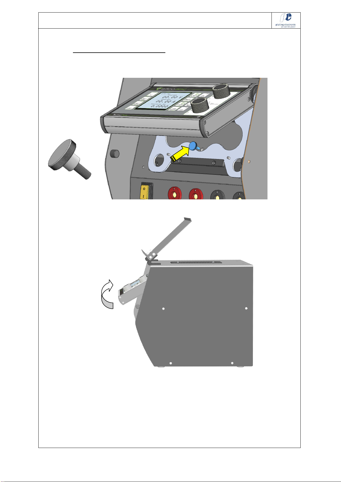
6.2 Transport lock for the control unit
Use the delivered screw to fix the control unit during transportation:
You can swing the control unit to adjust the angle of view.
SIFCOTechnoPlate Power Pack_2019-05-06_V1.5_e.doc 14/68
plating electronic GmbH - Rheinstraße 4 - D-79350 Sexau - Germany
Tel.: +49 (0)7641 / 93500-0 - Fax.: +49 (0) 7641 / 93500-999 E-Mail: info@plating.de
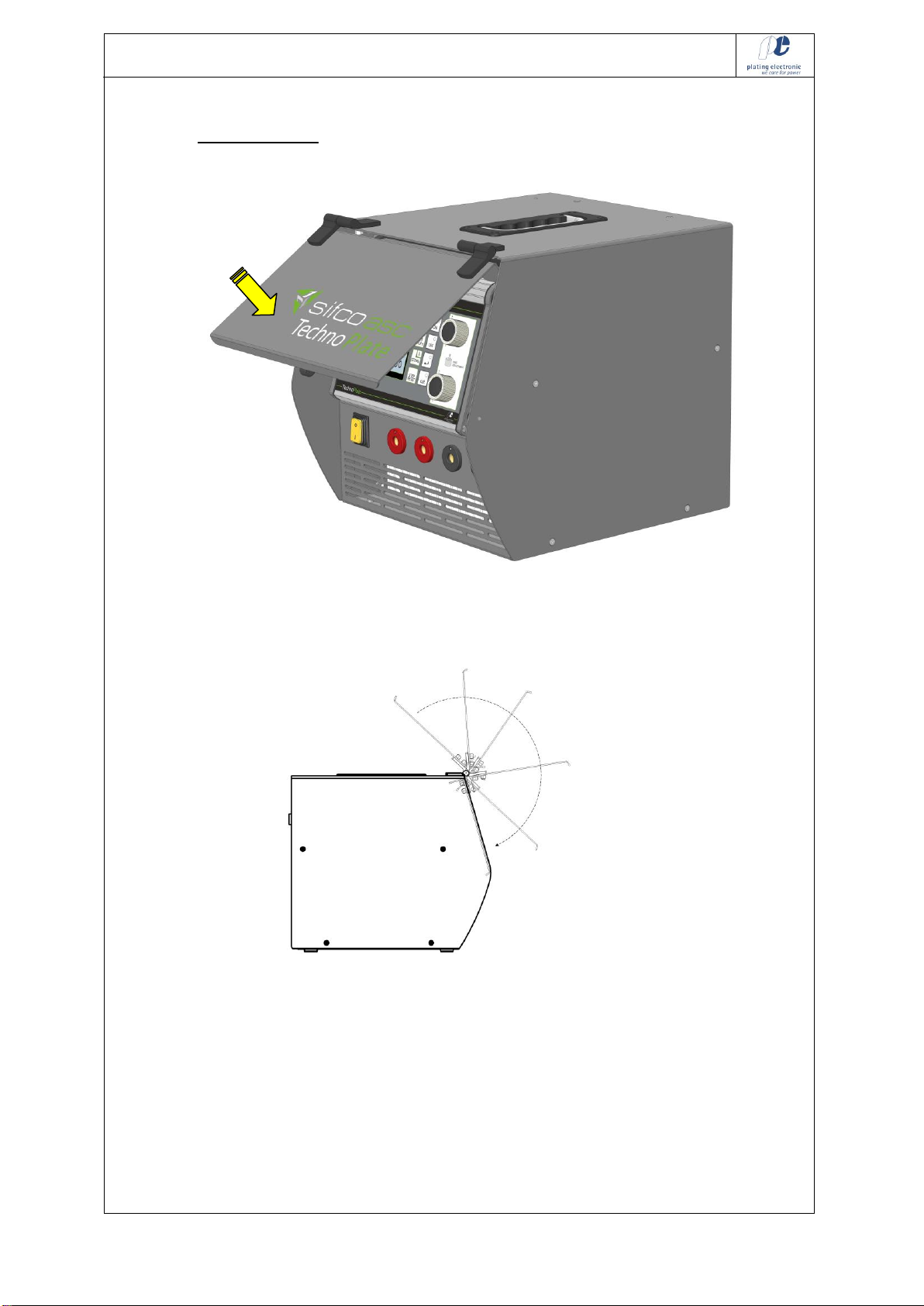
6.3 Protective cover
The protective cover plate is used to protect the control unit during
transportation. It should be closed if the device is not in use.
If the cover is opened, it could be used as a stand for manuals or process
instructions.
SIFCOTechnoPlate Power Pack_2019-05-06_V1.5_e.doc 15/68
plating electronic GmbH - Rheinstraße 4 - D-79350 Sexau - Germany
Tel.: +49 (0)7641 / 93500-0 - Fax.: +49 (0) 7641 / 93500-999 E-Mail: info@plating.de
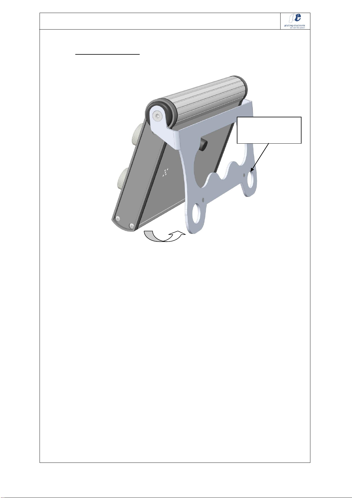
6.4 Control unit with stand
If unlatched, you can swing out the mounting plate of the control unit to
use it as a stand for desk top positioning (extension control cable
required, please order separately).
could also be hung
up (use holes in
plate)
SIFCOTechnoPlate Power Pack_2019-05-06_V1.5_e.doc 16/68
plating electronic GmbH - Rheinstraße 4 - D-79350 Sexau - Germany
Tel.: +49 (0)7641 / 93500-0 - Fax.: +49 (0) 7641 / 93500-999 E-Mail: info@plating.de
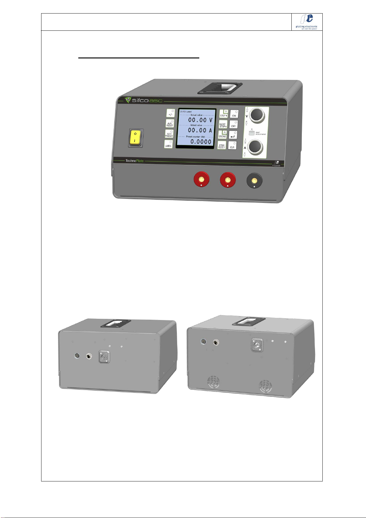
7 Devices 15 A / 20 V and 30 A / 20 V
The 15 A / 20 V type and the 30 A / 20 V type are the compact versions
of the TechnoPlate Power Pack.
The device 15 A / 20 V doesn’t require a fan or ventilation grille.
The control panel is firmly integrated.
The keypad, display and software functions are completely identical to
the larger rectifier version.
The two PLUS terminals have the same potential!
Type 6015A20V Type 6030A20V
Mains connection socket and RS485 BUS terminals are located in the
back panel.

SIFCOTechnoPlate Power Pack_2019-05-06_V1.5_e.doc 17/68
plating electronic GmbH - Rheinstraße 4 - D-79350 Sexau - Germany
Tel.: +49 (0)7641 / 93500-0 - Fax.: +49 (0) 7641 / 93500-999 E-Mail: info@plating.de
8 DC-output connection
Connect the DC-output connectors to the load. Check for right polarity
and contact.
Look for the DIN VDE 0298-4 / 2013-06
admitted cable cross section and the correct polarity.
Plug and turn for lock / unlock the connector.
The two PLUS terminals have the same potential!
The two MINUS terminals have the same potential!
The unit must be connected according to all applicable federal, state and
local electrical codes. The applicable phase current can be found on the
rectifier identification plate, located inside the unit.
Attention:
The connection of active loads such as batteries or DC-machines to the
DC-output-connectors will cause damages to the unit!
Please check:
Make sure that the mains supply cable is directly connected to your main
supply wall outlet.
Do not wire the power supply or the high-current cables into a roll or bind
the supply and the high-current wiring together with other wires.
Otherwise, overheating is possible.
+
+
SIFCOTechnoPlate Power Pack_2019-05-06_V1.5_e.doc 18/68
plating electronic GmbH - Rheinstraße 4 - D-79350 Sexau - Germany
Tel.: +49 (0)7641 / 93500-0 - Fax.: +49 (0) 7641 / 93500-999 E-Mail: info@plating.de
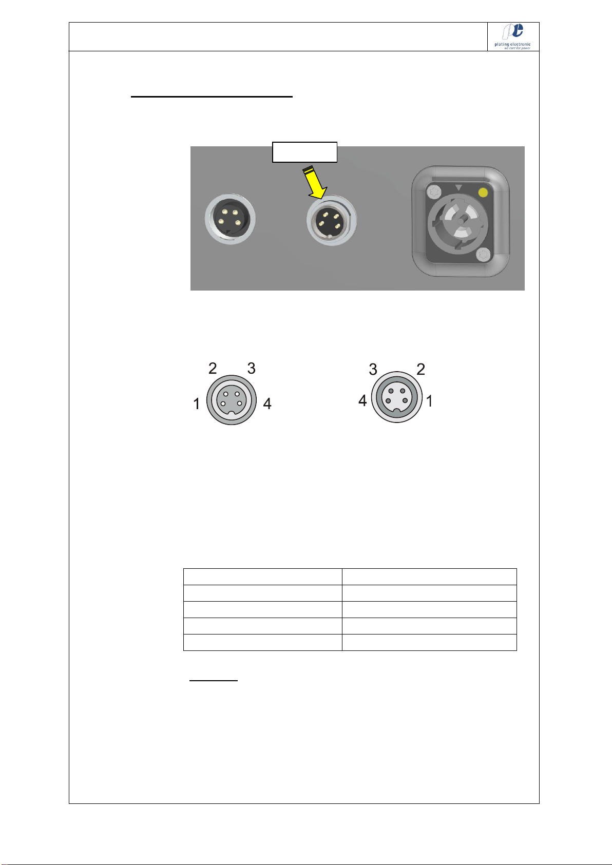
9 The RS485 BUS connection
There is a round four-pin socket located on the back plane of the device.
This is used for remote RS485 BUS control of the device.
Connect the RS485-BUS by the following scheme:
OUTPUT INPUT
BUS-output BUS-input
(„female“ socket) („male” socket)
The INPUT socket is used to connect the incoming BUS signal coming
from a BUS converter or a RS485 BUS interface.
The OUTPUT socket is used to connect the BUS terminator, if no
successive BUS device is looped into the RS485 BUS line.
Round 4-pin terminal
RS485 signal
1
+ VCC (only at BUS output)
2
BUS A
3
BUS B
4
GND (only at BUS output)
Attention! The 5 V DC signal that is used for the BUS terminator is
only available at the devices 15 A / 20 V and 30 A / 20 V!
BUS input

SIFCOTechnoPlate Power Pack_2019-05-06_V1.5_e.doc 19/68
plating electronic GmbH - Rheinstraße 4 - D-79350 Sexau - Germany
Tel.: +49 (0)7641 / 93500-0 - Fax.: +49 (0) 7641 / 93500-999 E-Mail: info@plating.de
9.1 Bus - terminator
4-pin female plug
The BUS terminator is to be installed at the BUS output socket of the last
participant within the RS485 BUS line.
9.2 Specification of the BUS cable
HELUKABEL type 2 x 2 x 0.22 mm2(AWG23)
2 pairs twisted, shielded; white, brown, green, yellow

SIFCOTechnoPlate Power Pack_2019-05-06_V1.5_e.doc 20/68
plating electronic GmbH - Rheinstraße 4 - D-79350 Sexau - Germany
Tel.: +49 (0)7641 / 93500-0 - Fax.: +49 (0) 7641 / 93500-999 E-Mail: info@plating.de
10 Mains supply
Supply voltage: see device type and specification list.
Use the delivered plug to connect the device to the corresponding mains
supply.
Respect the information on the rating plate, which is located on the right
side panel of the casing.
10.1 single-phase devices
Connecting scheme:
Outside view on the socket
N
PE
L
This manual suits for next models
5
Table of contents
Popular Power Supply manuals by other brands


DUNIWAY Stockroom
DUNIWAY Stockroom Terranova 752A instruction manual

BGS technic
BGS technic 3383 Safety and operating instructions

Honeywell
Honeywell 900P01 installation and replacement

SUNSLICE
SUNSLICE GRAVITY 432 instruction manual

Coolmax
Coolmax CUL-750B quick guide

M-system
M-system R3Y-SS16N instruction manual


