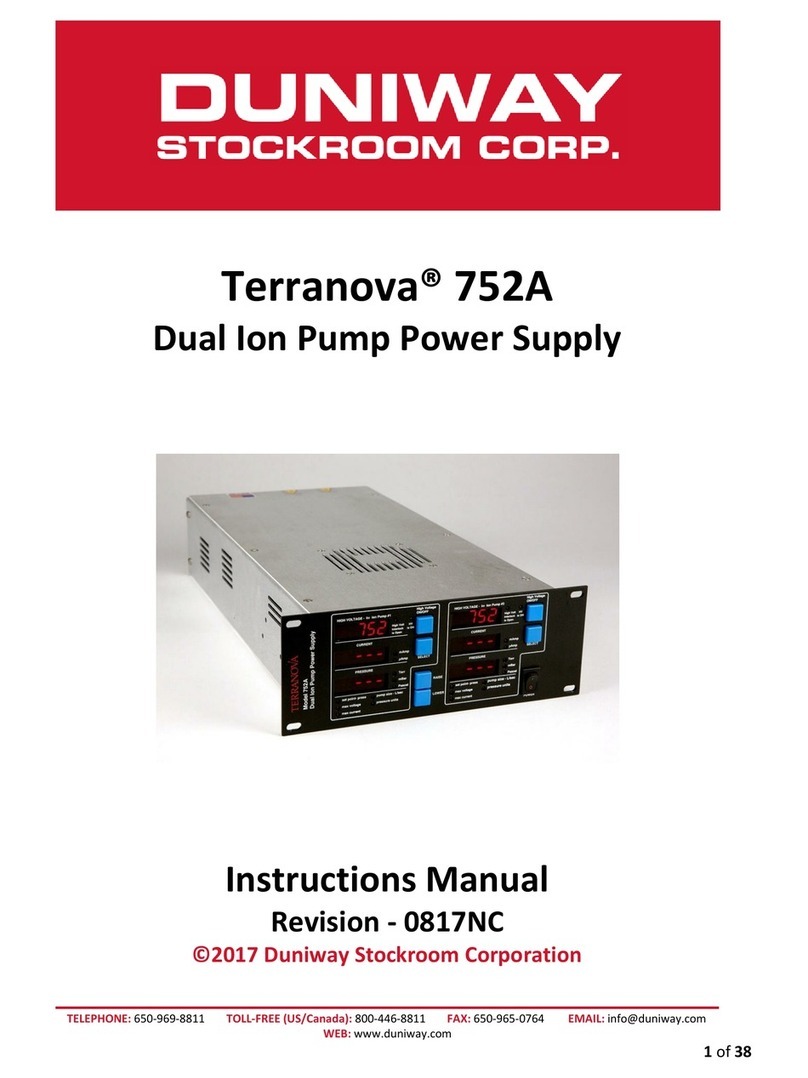
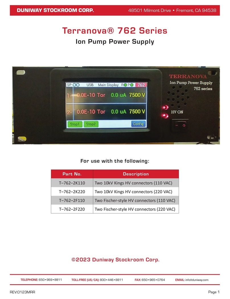
DUNIWAY Stockroom Terranova 752A User manual

EMAIL: info@duniway.comFAX: (650) 965•0764
TOLL-FREE [US/CA]: (800) 446•8811
TELEPHONE: (650) 969•8811
48501 Milmont Drive • Fremont, CA 94538
DUNIWAY STOCKROOM CORP. 48501 Milmont Drive • Fremont, CA 94538
DUNIWAY STOCKROOM CORP.
REV:0720NC
Terranova® 752A
Dual Ion Pump Power Supply
Instructions Manual
Part No. Description
T‒752A‒K110 Two 10kV Kings HV connectors (110 VAC)
T‒752A‒K220 Two 10kV Kings HV connectors (220 VAC)
T‒752A‒F110 Two Fischer-style HV connectors (110 VAC)
T‒752A‒F220 Two Fischer-style HV connectors (220 VAC)
©2020 Duniway Stockroom Corp.
For use with the following:

EMAIL: info@duniway.comFAX: (650) 965•0764
TOLL-FREE [US/CA]: (800) 446•8811
TELEPHONE: (650) 969•8811
48501 Milmont Drive • Fremont, CA 94538
DUNIWAY STOCKROOM CORP.
Page ii
Warranty
Duniway Stockroom Corporaon (“DSC”) warrants all Terranova® products to be free of defects in
material and workmanship for a period of one year from the date of shipment. At our opon, we
will repair or replace products which prove to be defecve during the warranty period. Liability
under this warranty is limited to repair or replacement of the defecve item(s). Shipping damage
is excluded from the scope of this warranty. Pressure gauges of all types are excluded from this
warranty.
Terranova® products are warranted not to fail to execute programming instrucons due to
defects in materials and workmanship. If DSC receives noce of such defects during the warranty
period, DSC will repair or replace rmware that does not execute its programming instrucon
due to such defects. DSC does not warrant that the operaon of the rmware or hardware will
be uninterrupted or error-free.
If this product is returned to DSC for warranty service, the Buyer will prepay shipping charges and
pay all dues and taxes for products returned to DSC. DSC will pay for the return of products to
the Buyer, except for products returned to the Buyer from a country other than the United States.
Please contact your Duniway Stockroom customer service representave for a Return Merchandise
Authorizaon (RMA) number if you need to return a Terranova® product.
Limitation of Warranty
The foregoing warranty does not apply to the defects resulng from:
1. Improper or inadequate maintenance by the Buyer,
2. Buyer-supplied interfacing,
3. Unauthorized modicaon or misuse,
4. Operaon outside of the environmental specicaons of the product, or
5. Improper site preparaon and maintenance.
The warranty set forth above is exclusive and no other warranty, whether wrien or oral, is
expressed or implied. DSC disclaims any implied warranes of merchantability and tness for a
parcular purpose.
Exclusive Remedies
The remedies provided herein are the Buyer’s sole and exclusive remedies. In no event will DSC be
liable for direct, indirect, special, incidental, or consequenal damages, including loss of prots,
whether based on contract, tort, or any other legal theory.

Page iii
Name: Michael Ricks
Title: General Manager
x
Place and Date
Fremont, CA on 02 July 2020
Remark: This Declaraon of Conformity replaces all previous ones for the above products.
ETL Certified and Listed
The named products conform or are cered to the following standards relang to
the safety of electrical equipment for measurement, control, and laboratory use:
UL: 61010-1:2012 Ed.3+R:29APR2016
CSA: C22.2#61010-1-12:2012 Ed.3+U1;U2;A1
Declaration of Conformity
2003309
EMC: EN 61000-6-1:2019
EN 61000-6-3:2007+A1:2011
EN 61326-1:2012RLV
LVD: EN 61010-1:2010+A1:2019
Product Name: Terranova® 751A Medium Ion Pump Power Supply
Terranova® 752A Dual Ion Pump Power Supply
The named products are in conformity with the following requirements of the EU direcves:
Electromagnec Compability Direcve (2014/30/EU)
Low Voltage Direcve (2014/35/EU)
We declare, under our sole responsibility, that the named products which display the
CE mark are in conformity with the following harmonized standards and/or normal
documents or technical specicaons:
Manufacturer: Duniway Stockroom Corp.
48501 Milmont Drive
Fremont, CA 94538

EMAIL: info@duniway.comFAX: (650) 965•0764
TOLL-FREE [US/CA]: (800) 446•8811
TELEPHONE: (650) 969•8811
48501 Milmont Drive • Fremont, CA 94538
DUNIWAY STOCKROOM CORP.
Page iv
Maintenance
The Terranova® 752A Dual Ion Pump Power Supply should not be serviced by the user. Any
maintenance must be performed by Duniway Stockroom personnel. If any service is required,
please contact your Duniway Stockroom customer service representave for a Return Merchandise
Authorizaon (RMA) number to return the Terranova® 752A.
Contacting Duniway Stockroom
Duniway Stockroom customer and technical service representaves are available via both
telephone and on-line for assistance in service requests, ordering, or any other quesons and
inquiries:
• For US and Canadian customers: (800) 446-8811
• For customers worldwide: (650) 969-8811
• General email inbox: info@duniway.com
• Website, catalog, and on-line store: www.duniway.com
Our Will Call is also available during normal business hours for in-person assistance or order
placement and pick-up:
48501 Milmont Drive
Fremont, CA 94538

EMAIL: info@duniway.comFAX: (650) 965•0764
TOLL-FREE [US/CA]: (800) 446•8811
TELEPHONE: (650) 969•8811
48501 Milmont Drive • Fremont, CA 94538
DUNIWAY STOCKROOM CORP.
Page v
The electricity hazard symbol is used to warn
personnel of a voltage hazard
The earth terminal symbol is used to indicate where
proper grounding pracces should be followed to
protect personnel against electrical shock and protect
equipment against possible damage.
WARNING!
The orange warning symbol is used to indicate a
hazard that may cause serious injury or death to
personnel if proper safety protocols are not followed.
The note symbol is used to emphasize helpful
informaon from the manual.
NOTE
Since 1976
General Manual Information
This manual contains important informaon regarding the safe operaon of the Terranova®752A
Dual Ion Pump Power Supply models listed on the cover page. We advise the customer read and
thoroughly understand the manual in its enrety before use. Any quesons should be addressed
to your Duniway Stockroom customer service representave.
Manual Symbol Key
The following symbols are used in this manual when the user should take parcular consideraon
CAUTION
The yellow cauon symbol is used to alert personnel
against pracces that may potenally damage
equipment.

EMAIL: info@duniway.comFAX: (650) 965•0764
TOLL-FREE [US/CA]: (800) 446•8811
TELEPHONE: (650) 969•8811
48501 Milmont Drive • Fremont, CA 94538
DUNIWAY STOCKROOM CORP.
Page vi
Specifications..............................................1
Accessories .................................................2
Front Panel Display....................................3
Switch and Buttons
Displays and LEDs
Rear Panel Connections............................5
Ion Pump Connections
Other Connections
Introduction.................................................9
Legacy Terranova®752
Pre-installation Settings ....................... 10
Mode of Operation
Setting the Mode of Operation
Changing the Output Polarity
Power-loss Restart
Disabling the Speaker
Installation................................................ 19
Installing the Terranova® 752A
Connecting the Ion Pump(s)
Safety Interlock
Power-up ................................................... 21
Channel Settings ..................................... 23
Channel Parameters
Ion Pump Operation ................................ 25
Start Phase
Normal Operation
Pressure Measurement
Cool-down Mode
Shutdown Mode
Set Point Operation ................................ 31
Analog Output .......................................... 32
High Voltage Monitor
Current Monitor
Serial Communication ............................ 35
Setting the Communication Standard
Setting the RS-485 Address
Query Characters
Command Characters
Troubleshooting ....................................... 43
Restoring Default Parameters
Leakage Current
Internal DIP Switch Setup
Changing the Input Fuse
Appendix: Note on set point relays .... A-1
Protective Circuits for Inductive Loads
Contents

EMAIL: info@duniway.comFAX: (650) 965•0764
TOLL-FREE [US/CA]: (800) 446•8811
TELEPHONE: (650) 969•8811
48501 Milmont Drive • Fremont, CA 94538
DUNIWAY STOCKROOM CORP.
Page vii
Figures
Figure 1. Terranova® 752A front view and dimensions...........................3
Figure 2. Terranova® 752A rear panel view...............................................5
Figure 3. DIP switch and JP9 jumper location......................................... 12
Figure 4. Component position for positive voltage output .................... 13
Figure 5. 4-pin header and HV diode diagram.......................................... 14
Figure 6. Ribbon cable above pin headers ................................................15
Figure 7. JP8 and JP13 pin header location............................................15
Figure 8. Terranova® 752A power vs. current graph ...........................27
Figure 9. Terranova® 752A power vs. (low) current graph .................27
Figure 10. Terranova® 752A voltage vs. current graph....................... 28
Figure 11. Relay operation graph ............................................................... 31
Figure 12. DIP Switch S2 diagram .............................................................37
Figure 13. Hexadecimal code 0FC0 DIP switch setup...........................46
Figure 14. Terranova® 752A AC power module ..................................... 47
Figure I. AZ5 relay maximum switching capacity ...................................A-1
Figure II. Example of “snubber” circuit ......................................................A-2

EMAIL: info@duniway.comFAX: (650) 965•0764
TOLL-FREE [US/CA]: (800) 446•8811
TELEPHONE: (650) 969•8811
48501 Milmont Drive • Fremont, CA 94538
DUNIWAY STOCKROOM CORP.
Page viii
Tables
Table 1. MISC I/O pin assignment .................................................................6
Table 2. AUXILIARY I/O pin assignment.......................................................7
Table 3. Terranova® 752A ground sense conditions............................. 20
Table 4. Channel default values ...................................................................23
Table 5. Channel parameter ranges ........................................................... 23
Table 6. Recommended ion pump starting pressures ........................... 25
Table 7. Linear current monitor voltage output.......................................32
Table 8. Logarithmic output and calculated current values.................. 33
Table 9. Serial I/O port pin configuration .................................................35
Table 10. Terranova® 752A RS-232 settings......................................... 35
Table 11. Serial communication query characters................................. 38
Table 12. Query communication examples ...............................................39
Table 13. Serial communication command characters .........................40
Table 14. Command communication examples........................................41
Table 15. Terranova® 752A display error codes.................................... 44
Table 16. Hexadecimal code 0FC0 output ................................................46

EMAIL: info@duniway.comFAX: (650) 965•0764
TOLL-FREE [US/CA]: (800) 446•8811
TELEPHONE: (650) 969•8811
48501 Milmont Drive • Fremont, CA 94538
DUNIWAY STOCKROOM CORP.
Page 1
Specifications
Operating Voltage Universal 100 V to 240 V AC @ 50 Hz to 60 Hz; 250 VA
Open Circuit Voltage* Operator Set 3500 to 7500 V DC
Polarity Posive (default)
Negave
Short Circuit Current* Operator Set 50 mA maximum
High Voltage Output Opons Two 10 kV Kings connectors
Two Fischer-style connectors
Overload Protection Fuse for input power
Automac power adjustment during Start Phase*
Automac shutdown for shorted output*
Display* Voltage 4 Red LEDs - 3 digits & polarity symbol (±X.XX)
Current 4 Red LEDs - 3 digits (XXX) with unit auto-range
Pressure 4 Red LEDs - 2 digits with exponent (X.X -X)
Pressure Units* Torr (default)
mbar
Pascal
Relay Rating Power 60 W / 120 VA (maximum)
Current 2 A (maximum)
Voltage 150 V DC or 300 V AC (maximum)
See "Appendix: Note on set point relays" for details
Dimensions Height 3.5 in. (89 mm)
Width 9.5 in. (241 mm)
Length 16.0 in. (406 mm)
Weight 6 lb. (2.7 kg)
Operating Environment Humidity 0 - 80 % (relave, non-condensing)
Temperature 0 °C to 40 °C
*Applies to each channel

EMAIL: info@duniway.comFAX: (650) 965•0764
TOLL-FREE [US/CA]: (800) 446•8811
TELEPHONE: (650) 969•8811
48501 Milmont Drive • Fremont, CA 94538
DUNIWAY STOCKROOM CORP.
Page 2
Accessories
Included Instrucon manual (Online)
One AC power cord with NEMA 5-15P plug and C13 connector (110 V AC)
One unterminated AC power cord with C13 connector (220 V AC)
Two slow-blow Type T, 2 A replacement fuses
One unterminated male 9-pin D-sub connector
One unterminated male 15-pin D-sub connector
One unterminated male 25-pin D-sub connector
Optional
(Sold separately)
RS232-TN751A RS-232 serial communicaon cable (10 )*
8000-0934-00 Half-rack adapter kit for one supply
8000-0934-01 Full-rack adapter kit for two supplies
10KV-100M Test plug
*Custom cable length is available upon request
Required
(Sold separately)
Ion pump(s) Visit our website under the Ion Pumps Overview
page at www.duniway.com/catalog/ion-pumps
Ion pump cable(s)
Visit our website under the Ion Pump Cables &
Connectors secon at
www.duniway.com/catalog/ion-pumps

EMAIL: info@duniway.comFAX: (650) 965•0764
TOLL-FREE [US/CA]: (800) 446•8811
TELEPHONE: (650) 969•8811
48501 Milmont Drive • Fremont, CA 94538
DUNIWAY STOCKROOM CORP.
Page 3
Figure 1. Terranova® 752A front view and dimensions
Switch and Buttons
1. POWER: Main ON/OFF switch for the Terranova® 752A
2. HIGH VOLTAGE ON/OFF: Buon to enable or disable voltage operaon; buon
must be depressed for more than 2 seconds to enable voltage output
3. SELECT: Buon to cycle through or select a parameter to modify; LED for the
selected parameter (e.g. SET POINT - PRESS) will become illuminated
4. RAISE: Buon to increase or change a parameter value
5. LOWER: Buon to decrease or change a parameter value
Front Panel Display
RAISE and LOWER buons are shared by both channels.
NOTE
Since 1976
HIGH VOLTAGE ON/OFF and SELECT buon descripons
apply to both channels.

EMAIL: info@duniway.comFAX: (650) 965•0764
TOLL-FREE [US/CA]: (800) 446•8811
TELEPHONE: (650) 969•8811
48501 Milmont Drive • Fremont, CA 94538
DUNIWAY STOCKROOM CORP.
Page 4
Displays and LEDs
Display
1. HIGH VOLTAGE: Outputs pump voltage and MAX VOLTAGE parameter
2. CURRENT: Outputs pump current, MAX CURRENT and PUMP SIZE parameters, and
Terranova® 752A status and informaon
3. PRESSURE: Outputs pump pressure, SET POINT parameter, and Terranova® 752A
status and informaon
LED
1. HV IS ON: Illuminates when voltage operaon is enabled
2. HIGH VOLT INTERLOCK IS OPEN: Illuminates when safety interlock circuit is open;
voltage operaon is disabled or interrupted when LED is illuminated
3. mAMP: Illuminates when CURRENT is in the milliampere (mA) range
4. μAMP: Illuminates when CURRENT is in the microampere (μA) range
5. TORR: Illuminates when torr is selected as the pressure unit
6. mBAR: Illuminates when mbar is selected as the pressure unit
7. PASCAL: Illuminates when Pascal is selected as the pressure unit
8. SET POINT - PRESS: Parameter to modify the set point pressure value
9. MAX VOLTAGE: Parameter to modify the Terranova® 752A voltage limit
10. MAX CURRENT: Parameter to modify the Terranova® 752A current limit
11. PUMP SIZE - L/SEC: Parameter to modify the ion pump speed
12. PRESSURE UNITS: Parameter to select the pressure units for all pressure values
Display and LED descripons apply to both channels
NOTE
Since 1976

EMAIL: info@duniway.comFAX: (650) 965•0764
TOLL-FREE [US/CA]: (800) 446•8811
TELEPHONE: (650) 969•8811
48501 Milmont Drive • Fremont, CA 94538
DUNIWAY STOCKROOM CORP.
Page 5
Figure 2. Terranova® 752A rear panel view
Ion Pump Connections
1. HIGH VOLTAGE 1: Channel #1 ion pump connecon
2. ION PUMP GROUND SENSE 1: Channel #1 safety interlock connecon
3. HIGH VOLTAGE 2: Channel #2 ion pump connecon
4. ION PUMP GROUND SENSE 2: Channel #2 safety interlock connecon
Other Connections
1. SAFETY GROUND: Earth ground connecon
2. RS-232 SERIAL I/O: 9-pin D-sub connector used for RS-232, RS-422, and RS-485
serial communicaon. See Table 10 on page 35 for pin assignment.
3. MISC I/O: 15-pin D-sub connector used for analog output, set point relay output,
and other voltage signals. See Table 1 for pin assignment.
4. AUXILIARY I/O: 25-pin D-sub connector used for analog output, set point relay
output, and other voltage signals. See Table 2 for pin assignment.
5. AC Power Module: Power cord socket and fuse holder
Rear Panel Connections

EMAIL: info@duniway.comFAX: (650) 965•0764
TOLL-FREE [US/CA]: (800) 446•8811
TELEPHONE: (650) 969•8811
48501 Milmont Drive • Fremont, CA 94538
DUNIWAY STOCKROOM CORP.
Page 6
PIN Function Output Description
1 CHANNEL 1 SET POINT relay Common See "Set Point Operaon"
2 CHANNEL 1 SET POINT relay Normally closed (NC) See "Set Point Operaon"
3Earth ground
4Digital ground
5 Voltage output -15 V See NOTE 1
6 Voltage output +15 V See NOTE 1
7 Voltage output +5 V See NOTE 2
8 CHANNEL 1 TTL input See "Mode of Operaon"
9 CHANNEL 1 SET POINT relay Normally open (NO) See "Set Point Operaon"
10 Voltage output +12 V See NOTE 1
11 CHANNEL 1 SET POINT status +5 V See NOTE 3
12 CHANNEL 1 current monitor See "Analog Output"
13 CHANNEL 1 (-) HV status +12 V See NOTE 4
14 CHANNEL 1 HV monitor See "Analog Output"
15 CHANNEL 1 (+) HV status +12 V See NOTE 5
NOTES
1. PIN 5-6, 10: Nominal output available for external use; current limit: 0.2 A
2. PIN 7: Nominal output available for external use; current limit: 0.2 A
(Same as PIN 12 on the AUXILIARY I/O port)
3. PIN 11: Nominal output available when CHANNEL 1 relay is acve
4. PIN 13: Nominal output available when CHANNEL 1 high voltage (HV)
operaon is ON and output polarity is negave
5. PIN 15: Nominal output available when CHANNEL 1 high voltage (HV)
operaon is ON and output polarity is posive
All MISC I/O funcons are idencal and not addional
to those found in the AUXILIARY I/O connector.
NOTE
Since 1976
Table 1. MISC I/O pin assignment

EMAIL: info@duniway.comFAX: (650) 965•0764
TOLL-FREE [US/CA]: (800) 446•8811
TELEPHONE: (650) 969•8811
48501 Milmont Drive • Fremont, CA 94538
DUNIWAY STOCKROOM CORP.
Page 7
PIN Function Output Description
1 CHANNEL 1 SET POINT relay Common See "Set Point Operaon"
2 CHANNEL 1 SET POINT relay Normally closed (NC) See "Set Point Operaon"
3CHANNEL 1 SET POINT status +5 V See NOTE 1
4CHANNEL 2 SET POINT relay Common See "Set Point Operaon"
5 CHANNEL 2 SET POINT relay Normally closed (NC) See "Set Point Operaon"
8 CHANNEL 2 current monitor See "Analog Output"
9 CHANNEL 2 HV monitor See "Analog Output"
10 CHANNEL 2 TTL input See "Mode of Operaon"
11 CHANNEL 1 (-) HV status +12 V See NOTE 2
12 Voltage output +5 V See NOTE 3
13 CHANNEL 1 TTL input See "Mode of Operaon"
14 CHANNEL 1 SET POINT relay Normally open (NO) See "Set Point Operaon"
15 Earth ground
16 Digital ground
17 CHANNEL 2 SET POINT relay Normally open (NO) See "Set Point Operaon"
18 CHANNEL 2 SET POINT status +5 V See NOTE 4
21 CHANNEL 2 (-) HV status +12 V See NOTE 5
22 CHANNEL 2 (+) HV status +12 V See NOTE 6
23 CHANNEL 1 current monitor See "Analog Output"
24 CHANNEL 1 HV monitor See "Analog Output"
25 CHANNEL 1 (+) HV status +12 V See NOTE 7
NOTES
1. PIN 3: Nominal output available when CHANNEL 1 relay is acve
2. PIN 11: Nominal output available when CHANNEL 1 voltage operaon is
enabled and output polarity is negave
3. PIN 12: Same as PIN 7 on the MISC I/O port
4. PIN 18: Same as PIN 3, but for CHANNEL 2
5. PIN 21: Same as PIN 11, but for CHANNEL 2
6. PIN 22: Same as PIN 25, but for CHANNEL 2
7. PIN 25: Nominal output available when CHANNEL 1 voltage operaon is
enabled and output polarity is posive
8. PIN 6-7, 19-20: Not available
Table 2. AUXILIARY I/O pin assignment

EMAIL: info@duniway.comFAX: (650) 965•0764
TOLL-FREE [US/CA]: (800) 446•8811
TELEPHONE: (650) 969•8811
48501 Milmont Drive • Fremont, CA 94538
DUNIWAY STOCKROOM CORP.
Page 9
Introduction
The Terranova® 752A Dual Ion Pump Power Supply is designed to start and operate a wide range
of ion pump models from a number of manufacturers. The Terranova® 752A is congured to
simultaneously-operate two ion pumps. Moreover, the user-changeable polarity provides the
ability to operate pumps that require either posive or negave high voltage. With programmable
parameters and a number of ways to exchange informaon, the Terranova® 752A's versality
allows its use in a number of applicaons.
Legacy Terranova®752
The legacy Terranova® 752 model has been disconnued and replaced by the Terranova® 752A.
Although the Terranova® 752 has been disconnued, the unit may sll be sent to Duniway
Stockroom for service. Please contact your Duniway Stockroom customer service representave
for further details.
Bodily harm or equipment damage can result due to electric shock
originang from the input AC voltage, internal unit potenals, or
high voltage output. The high voltage output hazard can exist either
from direct contact with the high voltage lead or due to loss or lack
of proper grounding from either the ion pump or Terranova® 752A.
WARNING!
CAUTION

EMAIL: info@duniway.comFAX: (650) 965•0764
TOLL-FREE [US/CA]: (800) 446•8811
TELEPHONE: (650) 969•8811
48501 Milmont Drive • Fremont, CA 94538
DUNIWAY STOCKROOM CORP.
Page 10
Pre-installation Settings
Mode of Operation
The Terranova® 752A has three dierent modes of operaon available: Mode 0, Mode 1, and
Mode 2. The selected mode of operaon applies to both channels. In all three modes, high
voltage operaon may be manually controlled via the HIGH VOLTAGE ON/OFF buon or through
serial communicaon.
Mode 0: Standard Operation
High voltage operaon and parameter input is conducted via the front panel or through serial
communicaon. High voltage output is dependent on the safety interlock circuit (see "Safety
Interlock" on page 20) of the channel. High voltage operaon will be interrupted if the
respecve safety interlock circuit is open or a ground fault is detected. Default mode of operaon.
Mode 1: Secondary Interlock
High voltage operaon and parameter input is conducted via the front panel or through serial
communicaon. However, high voltage output is dependent on a secondary interlock in addion
to the safety interlock circuit (see "Safety Interlock" on page 20) of the channel. The secondary
interlock is based on the voltage level of a +5 V TTL circuit. A user-installed switch can also be used
to operate the secondary interlock.
To commence and maintain high voltage output, the respecve safety interlock circuit must
remain closed and a LOW-level TTL signal must be connuously applied (or the installed switch
must remain closed). High voltage operaon will be interrupted if the respecve safety interlock
circuit is open, a ground fault is detected, or when a HIGH-level TTL signal is applied (or the
installed switch is opened) to the respecve channel. The TTL signal is input (or switch is installed)
between PIN 8 / PIN 3 of the MISCELLANEOUS port (PIN 13 / PIN 15 on the AUXILIARY port) for
CHANNEL 1 and PIN 10 / PIN 15 of the AUXILIARY port for CHANNEL 2. See Table 1 on page 6
and Table 2 on page 7 for pin conguraon.
If user aempts to start high voltage operaon with
the second interlock circuit open, error code ER6
will be output onto the respecve CURRENT display.
NOTE
Since 1976

EMAIL: info@duniway.comFAX: (650) 965•0764
TOLL-FREE [US/CA]: (800) 446•8811
TELEPHONE: (650) 969•8811
48501 Milmont Drive • Fremont, CA 94538
DUNIWAY STOCKROOM CORP.
Page 11
Mode 2: Remote Operation
High voltage operaon may be controlled directly via the front panel or remotely through either
serial communicaon or the voltage level of a +5 V TTL circuit. A user-installed switch can also be
used to control high voltage operaon. High voltage output is dependent on the respecve safety
interlock circuit (see "Safety Interlock" on page 20). High voltage operaon will be interrupted
if the respecve safety interlock circuit is open or a ground fault is detected. All unit parameters
must be set or changed via serial communicaon (see "Mode 2 Special Setup").
If using a TTL circuit (or switch), high voltage output will commence at a rising edge aer a LOW-
level TTL signal (or switch closure) is applied for more than 2 seconds. High voltage output will
be interrupted at a falling edge immediately aer a LOW-level TTL signal (or switch closure) is
applied. The TTL signal (or switch) is input between PIN 8 / PIN 3 of the MISCELLANEOUS port (or
PIN 13 / PIN 15 on the AUXILIARY port) for CHANNEL 1 and PIN 10 / PIN 15 of the AUXILIARY port
for CHANNEL 2. See Table 1 on page 6 and Table 2 on page 7 for pin conguraon.
Mode 2 Special Setup
In Mode 2, user may only scroll through unit parameters via the respecve SELECT buon. To set
or change parameters via the front panel, the Terranova® 752A must enter a special setup mode.
If user aempts to change parameters via the front panel, error code ER4 will be output on the
respecve CURRENT display.
To access the special setup mode:
1. Turn the control unit OFF via the POWER buon
2. Depress the CHANNEL 1 SELECT buon, and
3. Restart the control unit via the POWER switch
If successful, CHANNEL 1 HIGH VOLTAGE display will ash the code SU. Thereaer, user may
release the CHANNEL 1 SELECT buon and modify parameters via the front panel buons. To
return the Terranova® 752A to normal Mode 2 operaon, user must restart the control unit via
the POWER buon.
Other manuals for Terranova 752A
1
This manual suits for next models
4
Table of contents
Other DUNIWAY Stockroom Power Supply manuals
Popular Power Supply manuals by other brands

Sorensen
Sorensen DCR-B2 series installation manual

Delta Electronics
Delta Electronics GPS-200PB-143 Specifications

Thermaltake
Thermaltake Toughpower Grand TPG-850M user manual

Antec
Antec HCP-850 user manual

Matsusada Precision
Matsusada Precision VOL Series instruction manual

Clearaudio
Clearaudio smart power 24V user manual