SIG E-Pro Fieldbox User manual

2
2
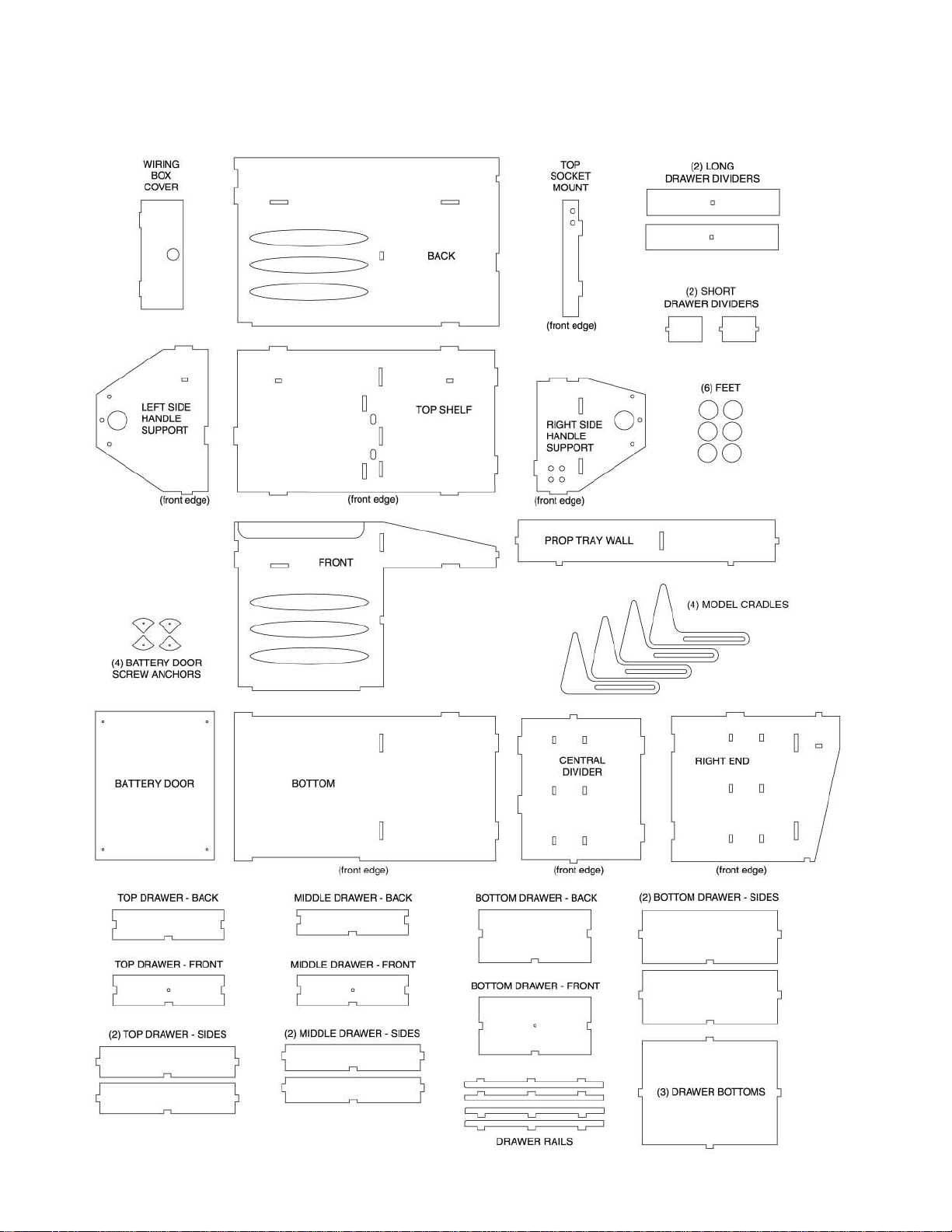
KEY TO LASER-CUT PARTS
Identify each laser cut part according to this diagram and mark the name on each part with a pencil.
2

SIG E-PRO FIELDBOX ASSEMBLY MANUAL
The SIG E-PRO FIELDBOX has been specially designed for the
hobbyist who operates electric powered models. The E-PRO box
features an extra large enclosed compartment for carrying one
or two high capacity lead-acid or gell-type charging batteries;
electrical banana plugs for quick connecting your field chargers to
the 12volt power supply; three drawers to hold the all your small
tools and extra parts; three large open top compartments for
your extra props and flight batteries; and adjustable cushioned
“cradles” on top of the box to hold your airplane off the ground
while you work on it or change the battery pack.
Virtually every part of the E-PRO FIELDBOX has been precisely
cad drawn and laser cut, assuring incredible accuracy and fit, and
making assembly quick and easy.
Tools & Supplies Required For Assembly:
Basic Hand Tools: Screwdriver, Pliers, 90OSquare
Sandpaper (various grits)
Sanding Block or Vibrating Electric Sander
Masking Tape
Pencil
Paint or Varnish Finish
Glue*
*Note: Carpenter’s wood glue, epoxy glue, or CA adhesives can
all be used to build this kit. However be aware that slow drying
adhesives will require clamps to hold the parts in proper position
while the glue dries.
We suggest that you study this assembly manual carefully to
understand the assembly sequence and final layout of the
flightbox. Plan ahead for the installation of your own specific
charging equipment and how it will mate up with the materials
supplied. In most cases, you should not need to make any
significant modifications to the layout of the box, but it is always
best to look and plan ahead.
It is also a good idea during assembly to trial fit each part “dry”
before applying any glue. That way you will know that the part will
slip cleanly into place after the glue is applied. Occasionally, you
may need to trim a sliver of wood off an edge or corner.
Notes Before Beginning:
Please note that references to "right" and "left" refer to your right
or left when you are looking directly at the front (drawer) side of
the box - with the battery on the left and the drawers on the right.
The construction of this flight box is based on an interlocking
tab-and-notch system. If all parts are put together in correct
sequence, and installed squarely in correct position on a flat
surface, the box should go together smoothly. Some plywood
pieces may be slightly warped when you take them out of the box,
but they will normally straighten out when installed in position.
You can save some time by building different parts of the box at
the same time. For instance, you can work on the drawers at the
same time parts of the main box are drying.
BEGIN ASSEMBLY
1) Glue two Drawer Rails, for the middle and top drawers, to the
right hand side of the Central Divider. Be careful to correctly
identify the bottom and top edges of the divider, as the tabs on top
are not symmetrical. Study the picture carefully.
2) Glue two corresponding Drawer Rails to the inner side of the
Right End part.You can identify the top front clearly, because the
top edge is sloping towards the front.
3) Glue the Central Divider and the Back in correct position on
the box Bottom, all at the same time. Be careful that the Bottom
rests on a flat surface and that there are no gaps between the
parts to assure that the box assembly stays square.
4) Glue the Top Shelf in position on the Central Divider and to
the Back. Again, avoid gaps between the components and make
sure everything remains square.
3
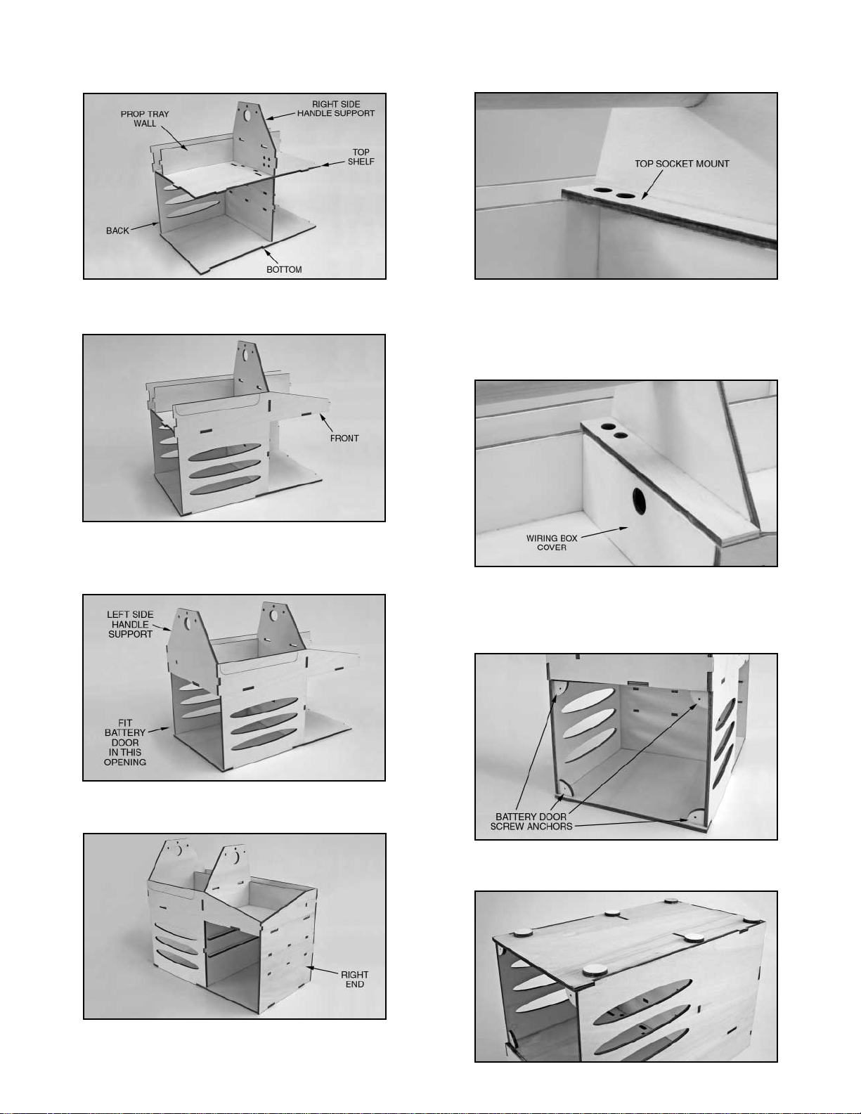
5) Glue the Right Side Handle Support and the Prop Tray Wall
in place. Keep everything square!
6) Glue the Front in position, applying glue everywhere it
contacts another piece.
7) Glue the Left Side Handle Support in position, applying glue
everywhere it contacts another piece. When dry, trial fit the
Battery Door in place and adjust the edges if necessary.
8) Glue the Right End in place. Make sure the Drawer Rails
(installed back in Step 2) are on the inside.
9) The Top Socket Mount is now glued to the left side of the
Right Side Handle Support and to the top of the box Front and the
Prop Tray Wall. The two holes should be towards the rear.
10) Fit the Wiring Box Cover into the space under theTop Socket
Mount. TheWiring Box Cover will not be glued in place! It should
be removable for wiring purposes. When you first try to slide the
cover in place, it will be tight. Slightly round the top and bottom
edges of the cover and bottom tabs until you get a nice tight fit.
11) Glue the four quarter-round Battery Door Screw Anchors in
the corners of the battery compartment opening. Be sure to install
them flush with the front and back sidewalls so that the Battery
Door will fit properly.
12) Turn the box over and glue the six round Feet to the
bottom of the box, in approximately the locations shown here.
4

13) Glue the four 1/4 dia.x 3/4" hardwood Dowels in place, which
will support the adjustable Model Cradle Arms.The dowels should
protrude equally from each side of the handle supports.
14) The hardwood dowel Handle is now fitted through the two
round holes in the Handle Supports and glued in place.
15) Trial-fit the Battery Door in place on the left hand side of the
box. Four #4x1/2” Screws are provided to attach it to the box.
DRAWER
ASSEMBLY
NOTE: Each of the
drawers is different in
height, therefore most
of the parts are not
interchangable.
However the front
panels of the two
upper drawers are
identical, as are all
three drawer bottoms.
All three drawers are assembled in the same way and the
following instructions apply to all of them.
1) Place a Drawer Bottom on your flat work surface. Glue the
Sides and the Back to the Bottom, each at 90O.
2) Last, glue the Drawer Front in place.
3) Each finished drawer should be sanded smooth and test
fitted into its appropriate opening in the front of the E-Pro box.
Make any adjustments required to achieve a smooth, flush fit. Do
not install the Drawer Knobs or Dividers at this time. Proceed to
next step.
FINISHING THE E-PRO FIELDBOX
Sand all surfaces of the box and drawers smooth in preperation
for applying a protective finish. You can paint your box with any
weatherproof varnish or paint that is suitable for use on wood. We
used water-based clear polyurethane varnish and have been very
happy with the results. It’s tough and waterproof when dry. Once
the box is thoroughly dry you can proceed with the final assembly.
1) Install the Drawer Pull Knobs on the front of each drawer with
the #12x3/4” Screws provided.
2) A set of two Long Dividers and two Short Dividers are
provided for use in the top drawer, if you desire. They are
optional and can be installed as you see fit. You can use just one,
or all four, in different arrangements. You can see in the photo on
the front of this manual how we installed 3 of the dividers (2 long
and 1 short) in the top drawer.
3) Cut the 3" long “hook and loop” (Velcro®) tape provided into 3
equal 1” long pieces. Remove the paper backing and stick the
“loop” (fuzzy) piece in the center on the back of each drawer.
Then remove the backing from the mating“hook” piece and attach
it to the piece already on the back of the drawer - with the
adhesive side exposed. Slide the drawer into it's proper slot and
push it all the way to the rear with enough force so that the velcro
strip sticks to the back of the box when you pull the drawer out.
5

WIRING THE E-PRO FIELDBOX
1) Install the six Banana Plug Sockets that are provided. Install
4 of them (2 red, 2 black) in the 4 round holes in the bottom of the
Right Side Handle Support. Install the other 2 sockets (1 red,
1 black) in the 2 holes in the Top Socket Mount. Note: These
sockets provide you with three 12volt charging stations for
powering your 12volt field equipment. Install the Banana Plugs
themselves on your field charger(s) or other 12volt accessories.
2) Cut the supplied 36” long piece of Red Electrical Wire in half,
giving you two 18” long pieces. Do the same for the Black
Electrical Wire provided, making two 18” long pieces.
3) Strip both ends of each wire. Then“tin”the bare ends of each
wire with solder to make them stiff and keep them from unraveling
(i.e.“tinning” means to melt solder into the bare end of each wire).
4) Twist one end of both Red
Wires together and solder on
a Battery Connector (not
supplied) that will fit your
charging battery. Do the
same to both Black Wires -
joining one end of each Black
Wire together and soldering
on a suitable Battery
Connector.
5) Poke one Black and one Red Wire up from the battery
compartment through the oblong hole nearest the back side of the
four Banana Plug Sockets in the Right Handle Support. Solder
the Black Wire to both Black Sockets, and the Red Wire to both
Red Sockets. Note:You will need to strip a bit more plastic off the
ends of the wires to allow you to connect both same colored
sockets to one wire, as shown.
6) Thread the second set of Red and BlackWires up through the
oblong hole nearest the two Banana Plug Sockets in the Top
Socket Mount. Solder each wire to it’s corresponding socket.
7) A strip of 1” wide X 19-1/2” long “dual-lock” plastic tape is
provided for holding your charging battery in place. Cut the strip
into four equal length pieces, and apply two of the pieces to the
bottom of your battery and the other two to the floor of the battery
compartment. This material makes a very strong connection and
will keep your heavy charging battery from shifting.
8) Install your 12 volt charging battery and connect the red and
black wires. IMPORTANT: Always make sure the battery clips
are shielded to prevent shorting out, and that they are firmly
connected to the battery to prevent arcing.
6
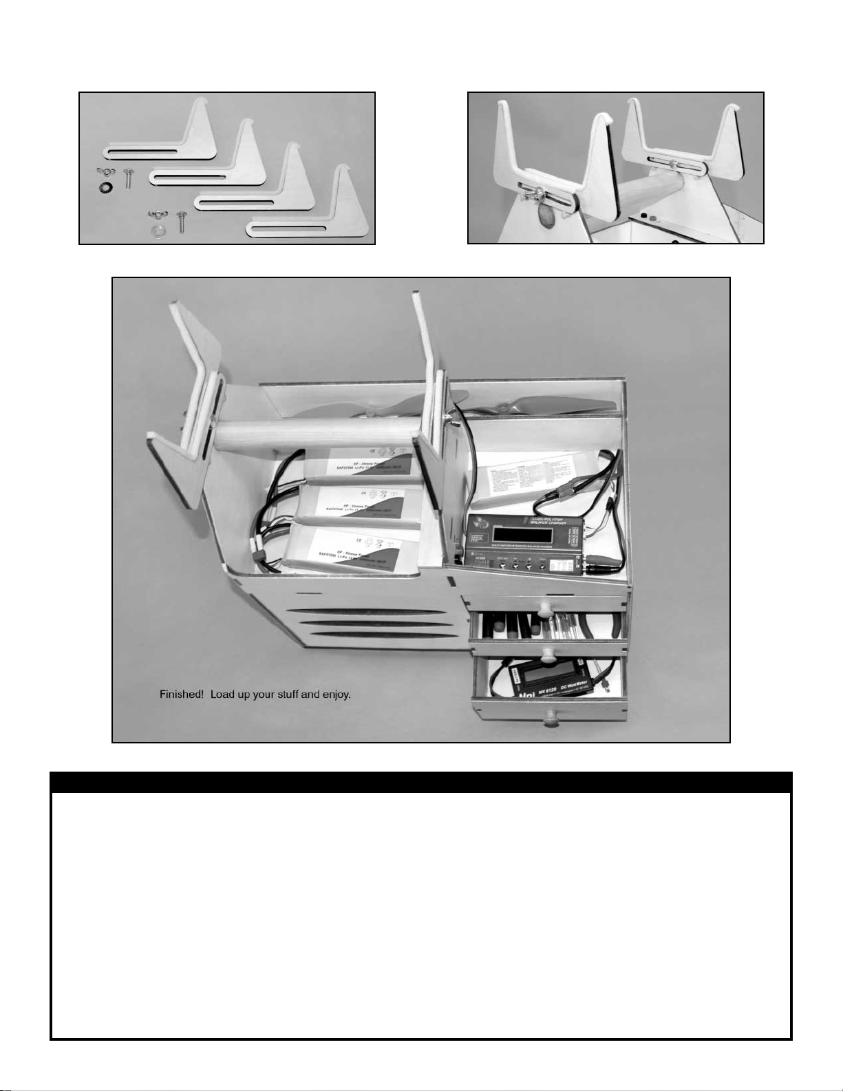
9) Prepare the four adjustable Model Cradle Arms by applying
the soft self-adhesive Cushion Tape on the top surfaces. 10) Install the Model Cradle Arms on top of the box with the
1/4-20 x 1” Carriage Bolts, Washers, and Wing Nuts provided.
CUSTOMER SERVICE
SIG MFG. CO., INC. is committed to your success in both assembling and using the E-PRO FIELDBOX kit. Should you have any
questions about building this kit or discover any missing or damaged parts, please feel free to contact us.
SIG MFG. CO., INC.
PO Box 520
401 South Front Street
Montezuma, IA 50171-0520
PHONE: (641) 623-5154
FAX: (641) 623-3922
SIG WEB SITE: www.sigmfg.com
LIMIT OF LIABILITY
The craftsmanship, attention to detail, and actions of the builder of this kit will ultimately determine the its final appearance and usefullness. SIG MFG. CO.’s obligation
shall be to replace those parts of the kit proven to be defective or missing. The user shall determine the suitability of the product for his or her intended use and shall
assume all risk and liability in connection therewith.
7

With a large 12volt battery on board,
(sometimes two, if you fly electrics) and a
full compliment of tools, a field box can
get really heavy in a hurry! If you want to
make it a lot easier to get your field box
from the car to the flight line and back, take
a look at this SIG FIELDBOX WHEEL KIT. This
kit provides everything you need to make your field box more mobile. You get: (2) sturdy 3-1/2”
diameter Wheels, a long pre-formed Aluminum Handle, Plastic Hand Grip, Axle, Axle Mounts, Handle
Mount, and complete Hardware. Installation is easy and fast. The light weight aluminum handle is
quickly removeable by loosening two wingbolts, to make it easier to fit in your vehicle.
8
ADD WHEELS TOYOUR E-PRO FIELDBOX!
with the
DON’T CARRY IT!
ROLL IT!
Order No. SIGBX004B
FIELDBOX
WHEEL KIT
Universal Design - Now You Can
Add Wheels And A Handle To
Practically Any Wood Field Box!
Grooved Hardwood Axle Mount Blocks epoxy permanently onto the
bottom of your field box. Wheels and Axle are easily removable. Hardwood Handle Mount is epoxied permanently to the side of your
field box. The Aluminum Handle can be quickly removed for transport.
OPTIONAL
Table of contents
Popular Indoor Furnishing manuals by other brands


Walker Edison
Walker Edison PROD39DT Assembly instructions

Wholesale Interiors
Wholesale Interiors BBT6661 Assembly instructions

Forte
Forte Havanna HVNS411R Assembling Instruction

Multistore
Multistore EXC-CNR Assembly instructions

DHP
DHP Grayson 4130039WE manual

Steelcase
Steelcase Adjustable Keyboard and Mechanism manual

fantastic furniture
fantastic furniture HAYMAN Storage Mirror White manual

KIDSMILL
KIDSMILL VINCE 11704256 user manual

Stryker
Stryker Traditional 4400-880-000 quick start guide

Home Decorators Collection
Home Decorators Collection Oxford BF-20429 Assembly instructions

Stanley
Stanley HTC-275S Use and care guide

John Greenleaf
John Greenleaf Wessex Create Achair 468W manual