Sigenergy EVAC 7 4G T2 WH User manual

Sigen EV AC Charger
Installation Guide
Sigen EVAC (7, 11, 22) 4G T2 WH
Sigen EVAC (7, 11, 22) 4G T2SH WH
Version: 02
Release date: 2024-01-25
1
1 Introduction
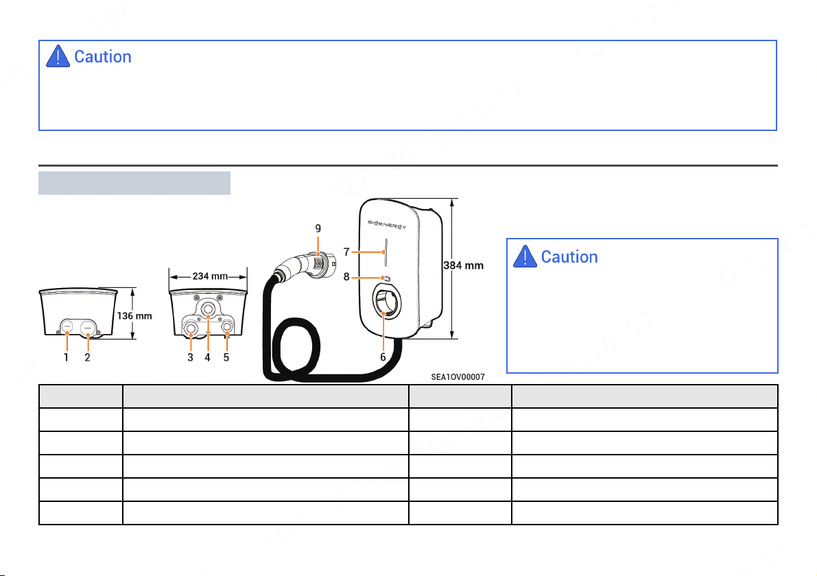
No. Description No. Description
1Top routing hole for communication cable 2Top routing hole for AC input cable
3Bottom routing hole for AC input cable 4Bottom routing hole for charging cable
5Bottom routing hole for communication cable 6Type 2 charging connector holder
7Indicator 8RFID card reading area
9Charging connector - -
•You are advised to connect cables through
bottom routing holes (holes 3 and 5).
•If cables are connected through top routing
holes (holes 1 and 2), please install the
equipment in a sheltered location to prevent
water ingress after prolonged water
accumulation on the top.
•Trained or experienced electrical personnel are required to operate the equipment.
•Operators should be familiar with national/regional laws, regulations and standards, the structure and working principle of relevant systems.
•Please read carefully the operating requirements and precautions in this document and Important Notice before operating. Failure to do so may
result in damage to the equipment that is not covered by the warranty.
Sigen EVAC 7/11/22 4G T2 WH
2
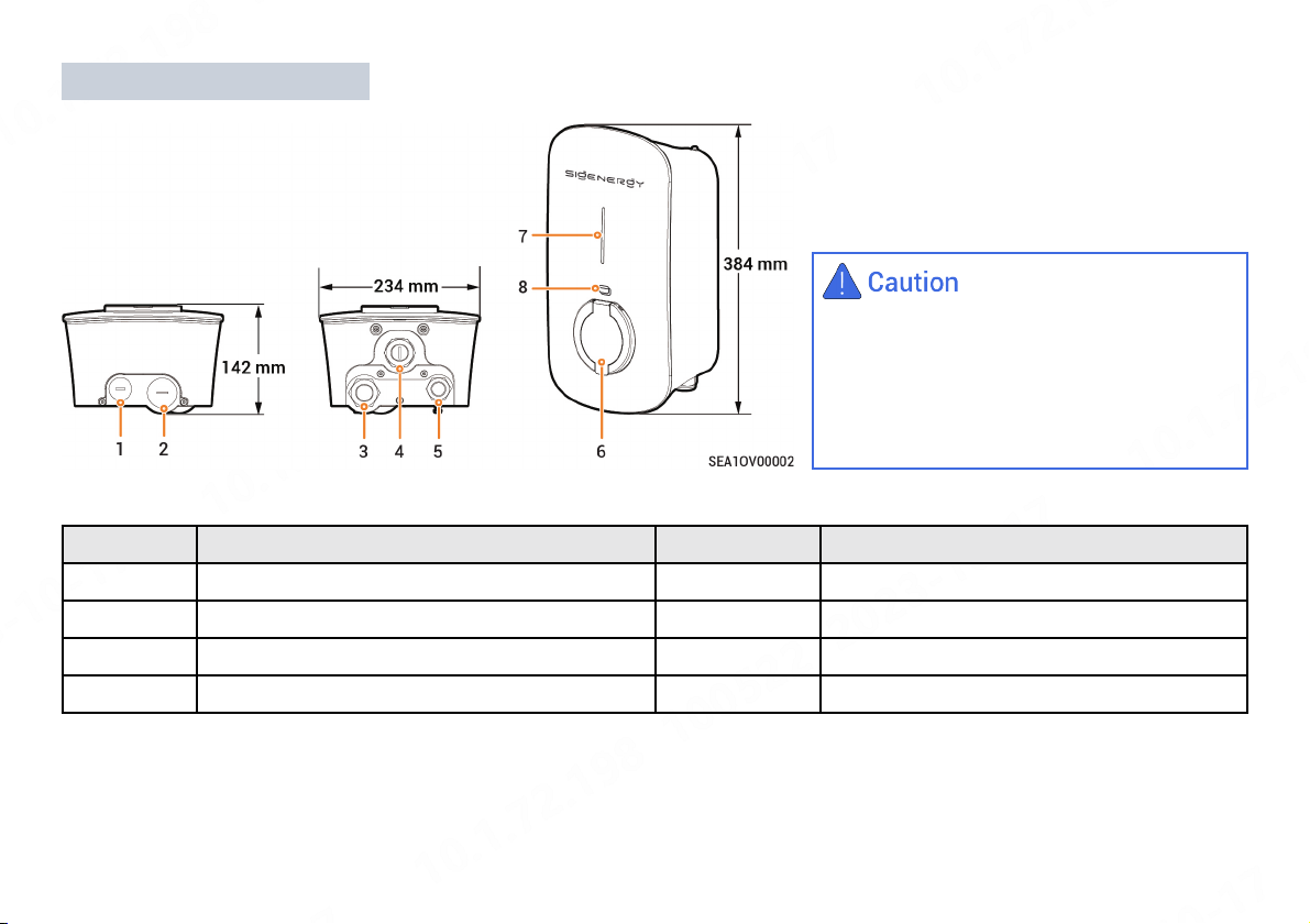
No. Description No. Description
1Top routing hole for communication cable 2Top routing hole for AC input cable
3Bottom routing hole for AC input cable 4(Reserved) Bottom routing hole
5Bottom routing hole for communication cable 6Type 2 charger socket with protective door
7Indicator 8RFID card reading area
•You are advised to connect cables through
bottom routing holes (holes 3 and 5).
•If cables are connected through top routing
holes (holes 1 and 2), please install the
equipment in a sheltered location to prevent
water ingress after prolonged water
accumulation on the top.
Sigen EVAC 7/11/22 4G T2SH WH
3
Digital torque
open-end wrench
2 Pre-installation Check
•According to the packing list, check whether the components are complete and in good appearance. If any abnormality occurs, contact your
sales agent in time.
•Check personal protective equipment and installation tools to ensure that they are complete; If not, please make them up.
•Check the customer-provided cable to ensure that the quantity and specifications are correct; if not, prepare again.
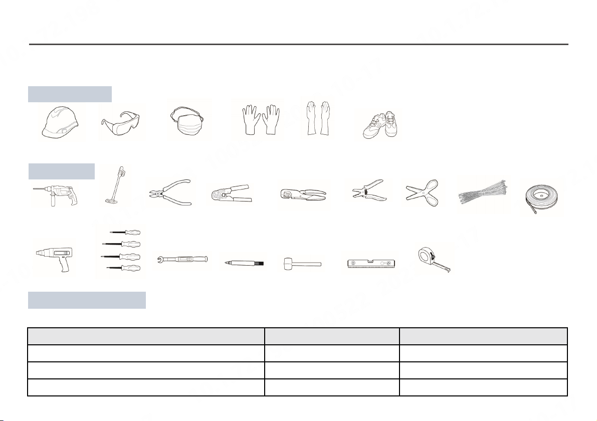
Installation tool
Protective equipment
Safety hat Safety glasses Dust mask Protective gloves Insulating gloves Insulating shoes
Power
drill
Crimp tool Crimping pliers Wire stripperWire cutter Cable tieScissorsVacuum
cleaner Heat shrinkable
sleeve
Heat gun Insulation
screwdriver set Rubber malletMarker Level Tape measure
Self-supplied pre-AC switch
Users should prepare type B MCB compliant with IEC/EN 60898 with recommended specifications shown below. Users can omit this requirement if
they have installed compliant AC switches.
Model Number of Poles, MCB Rated Current, MCB
Sigen EVAC 7 4G T2 WH, Sigen EVAC 7 4G T2SH WH 1P+N 40 A
Sigen EVAC 11 4G T2 WH, Sigen EVAC 11 4G T2SH WH 3P+N 20 A
Sigen EVAC 22 4G T2 WH, Sigen EVAC 22 4G T2SH WH 3P+N 40 A
4
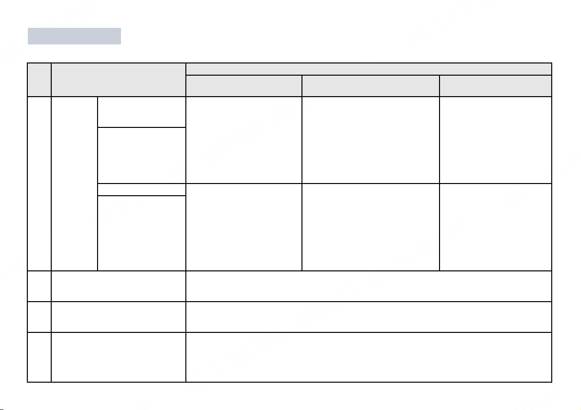
Self-supplied Cables
The grid power options include TT, TN-S, TN-C-S, and IT. Users can prepare cables according to their local grid power mode.
No. Cable Name Recommended Specification
Sigen EVAC 7 4G T2 WH
Sigen EVAC 7 4G T2SH WH
Sigen EVAC 11 4G T2 WH
Sigen EVAC 11 4G T2SH WH
Sigen EVAC 22 4G T2 WH
Sigen EVAC 22 4G T2SH WH
1AC input
cable
Three-phase five-wire
system
(L1/L2/L3/N/PE)
-Five-core/four-core copper core
cables for outdoor use
•Cable temperature resistance: ≥
90°C
•Outer diameter: 13 mm to 20 mm
•Current: 16 A
•Cross-sectional area of conductor:
2.5 mm² to 4 mm²
Five-core/four-core copper
core cables for outdoor use
•Cable temperature
resistance: ≥ 90°C
•Outer diameter: 13 mm to
20 mm
•Current: 32 A
•Cross-sectional area of
conductor: 6 mm²
Three-phase four-wire
system (L1/L2/L3/PE)
Two phases (L1/L2/PE) Three-core copper core cables
for outdoor use
•Cable temperature
resistance: ≥ 90°C
•Outer diameter: 13 mm to
20 mm
•Current: 32 A
•Cross-sectional area of
conductor: 6 mm²
- -
Single phase (L/N/PE)
2RS485 signal cable/DO signal
cable/Linky smart meter signal cable
Cables or two-core shielded twisted pair for outdoor use
•Conductor cross-sectional area: 0.2 mm² to 1.5 mm²
•Outer diameter: 5 mm to 7 mm
3RJ45 network cable Shielded twisted pair for outdoor use
•Conductor cross-sectional area: 0.129 mm² to 0.205 mm²
•Outer diameter: 5 mm to 7 mm
4(Optional) PEN control line (only
applicable to the UK)
Two-core copper core cables for outdoor use
•Cable temperature resistance: ≥ 90°C
•Voltage requirement: ≥ 300 V/500 V
•Cross-sectional area of conductor: 0.75 mm² to 1.5 mm²
•Outer diameter: 5 mm to 7 mm

3 Equipment Installation
5
Installation environment
Installation position
Mounting surface
•Do not install the equipment in smoky, flammable, explosive, or corrosive
environments.
•Avoid exposing the equipment to direct sunlight, rain, standing water, snow, or
dust. Install the equipment in a sheltered place. Take preventive measures in
operating areas prone to natural disasters such as floods, mudslides,
earthquakes, and typhoons.
•Do not install the equipment in an environment with strong electromagnetic
interference.
•Ensure that the temperature and humidity of the installation environment
comply with the equipment's requirements.
•The equipment should be installed in an area that is at least 500 m away from
corrosion sources that may result in salt damage or acid damage (corrosion
sources include but are not limited to seaside, thermal power plants, chemical
plants, smelters, coal plants, rubber plants, and electroplating plants).
•Do not tilt or overturn the equipment to ensure that it is installed horizontally.
•Do not install the equipment in a place easily touched by children.
•Do not install the equipment in mobile scenarios such as RVS, cruise ships,
and trains.
•You are advised to install the equipment in a position that is easy to operate,
maintain, and view indicator status.
•When installing the equipment in the garage, do not install the equipment in
the position where the vehicle passes through to avoid collision.
•Do not install the equipment on a flammable carrier.
•The installation carrier must meet load-bearing requirements. Solid brick-
concrete structure, concrete walls are recommended.
•The surface of the installation carrier must be smooth and the installation
area must meet the installation space requirements.
•No water or electricity is routed inside the carrier to prevent drilling hazards
during equipment installation.
The warranty applies when the equipment has been installed properly for its intended use and in accordance with the operating instructions.

6
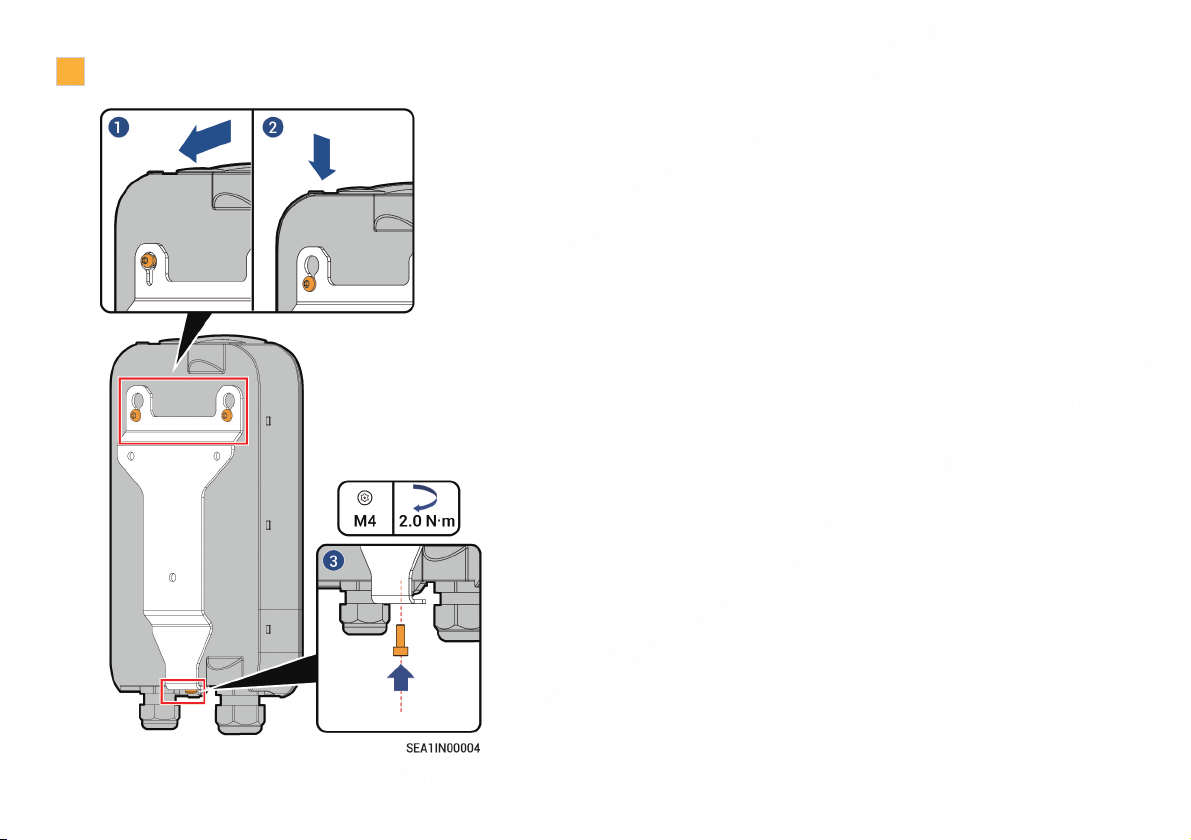
4 Installation
1Take the equipment from its package and disassemble it.
2
Install the wall mounting fittings.
Panel Terminal block
Wall
7
3Install and secure the terminal block.
8
5 Cable Connection
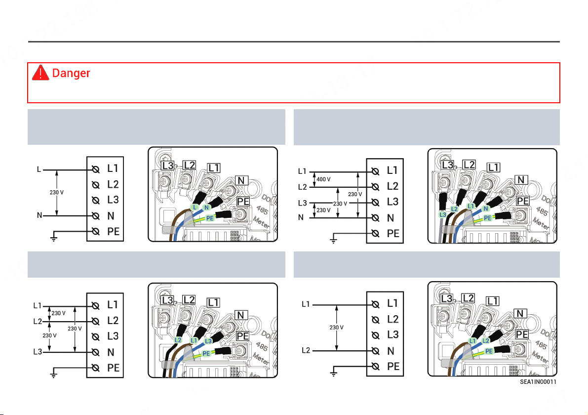
5.1 Description of Grid Power Supply Modes
Sigen EVAC supports the grid power supply methods shown in the diagram, please strictly refer to the diagram to connect the AC
cable. The device can not operate if the connection is wrong; safety hazard can be caused if the PE wire is wrongly connected.
Power grid Sigen EVAC Power grid Sigen EVAC
Power grid Sigen EVAC Power grid Sigen EVAC
Three-phase five-wire system (L1/L2/L3/N/PE)
Phase-tophase voltage (L-L): 400 V
Phase-to-neutral voltage (L-N): 230 V
Three-phase four-wire system (L1/L2/L3/PE)
Phase-tophase voltage (L-L): 230 V
Two phases (L1/L2/PE)
Phase-tophase voltage (L-L): 230 V
Single-phase three-wire system (L/N/PE)
Phase-to-neutral voltage (L-N): 230 V
9
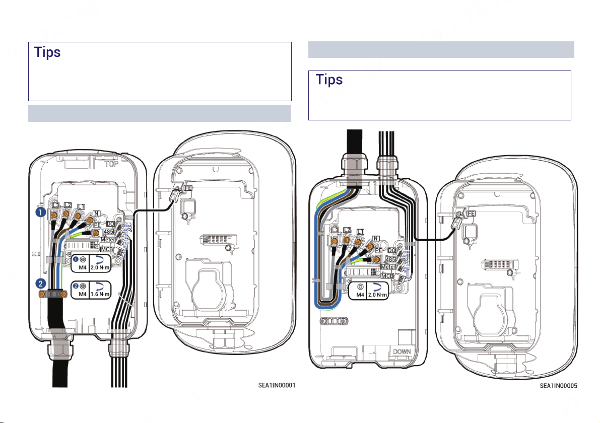
5.2 Routing
Bottom Routing (recommended)
•This section describes the routing method using the three-phase
five-wire system.
•You are recommended to place the PE core at the lowest layer
during routing.
Top Routing
When top routing is used, the equipment top should be adequately
protected to prevent water ingress caused by prolonged water
accumulation.

The stripping length (A) of cable insulation is determined
by the Sigen EVAC port to which cables are connected.
10
Top Routing 5.3 AC Input Cable Connection
This section will take three-phase five-wire system
as an example to introduce the connection procedure.
Install the water-proof connector at the bottom to the top before
connecting cables.
11
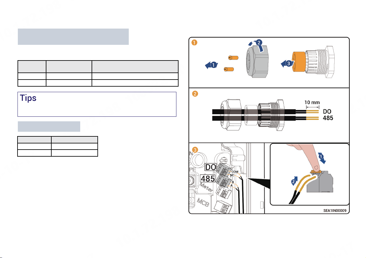
5.4 RS485/DO Signal Cable Connection
PIN Definitions Sigen Sensor TP-CT120-DH
(SDM630 MCT 40mA)
RS485_A RS485 signal_A+ 14
RS485_B RS485 signal_B-13
Definitions of RS485 Ports and Connection
Relationship with Power Sensor
Definitions of DO Ports
PIN Definitions
COM Output signal COM
NC Output signal NC
For appearance and connection details of the Power Sensor, refer to
the User Manual supplied with the product.
Connect one end of the RS485 signal cable to Sigen EVAC and the
other end to Power Sensor.

12
5.5 (Optional) Connection of PEN control lines
PIN Definitions Sigen EVAC Smart PEN Breaker[1]
NOutput N level Terminal C1
LOutput L level Terminal C2
Definitions of MCB Ports and Connection Relationship with Sigen
EVAC Smart PEN Breaker
Note [1]: The corresponding wiring terminal of the Sigen EVAC Smart
PEN Breaker
For information on the specific installation and wiring operation of the
Sigen EVAC Smart PEN Breaker, please refer to the user manual
supplied with the product.
Sigen EVAC Smart PEN Breaker
Sigen EVAC

13
5.6 (Optional) Connection of Linky Smart Meter Signal Cable
Definitions of Meter Ports and Connection Relationship with Linky
Smart Meter
For information on the specific installation and wiring operation of the
Linky smart meter, please refer to the user manual supplied with the
product.
PIN TIC port of Linky Smart Meter
Meter_IN I1
Meter_OUT I2
14
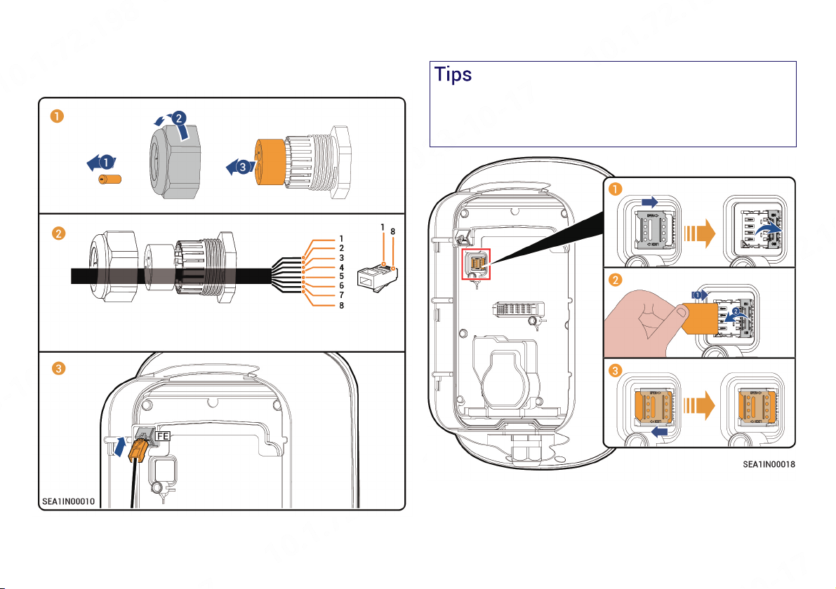
5.7 FE Signal Cable Connection
Connect one end of the FE signal cable to Sigen EVAC and the other
end to a router.
①White orange ②Orange ③White green ④Blue
⑤White blue ⑥Green ⑦White brown ⑧Brown
5.8 Installation of SIM Card
•Install the SIM card when 4G communication is enabled.
•SIM cards are supplied by users and standard SIM cards are
recommended (size: 25 mm×15 mm, capacity ≥ 64 KB, traffic ≥
128 MB/month).
15
No. Check Item
1The equipment is securely installed.
2AC cables and signal cables are properly connected
without omission.
3Lock screws or terminals are installed in place without any
looseness.
4Cutouts of cable ties are free of burr or sharp edges.
5Unused ports are protected with water-proof covers or
plugs.
6No construction residue inside and outside the equipment.
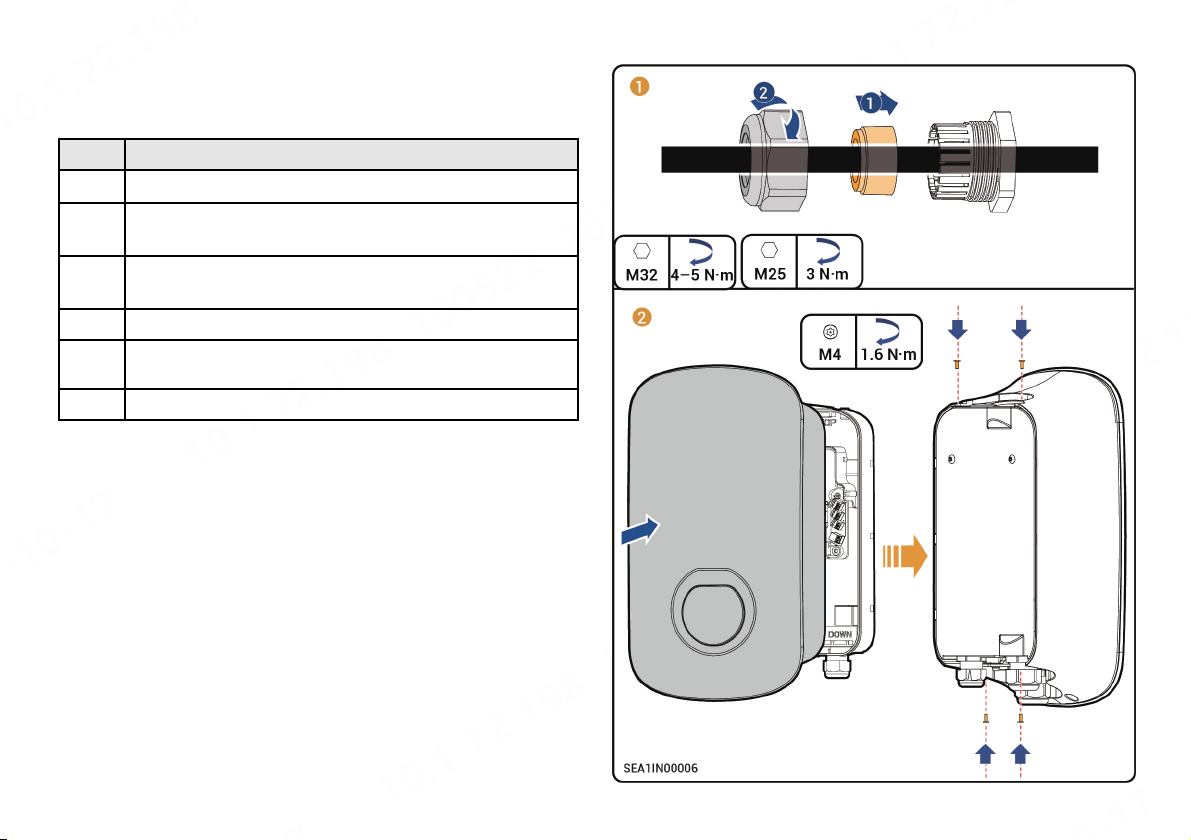
Check the following items against the provided table, tighten routing
holes, and install the panel.
5.9 Installing Panel

16
5.10 Installing Cable Holder and Placing Charging Connector
1Install the cable holder.
Wall
This section applies only to Sigen EVAC 7/11/22 4G T2 WH.
2Place the charging connector.

17
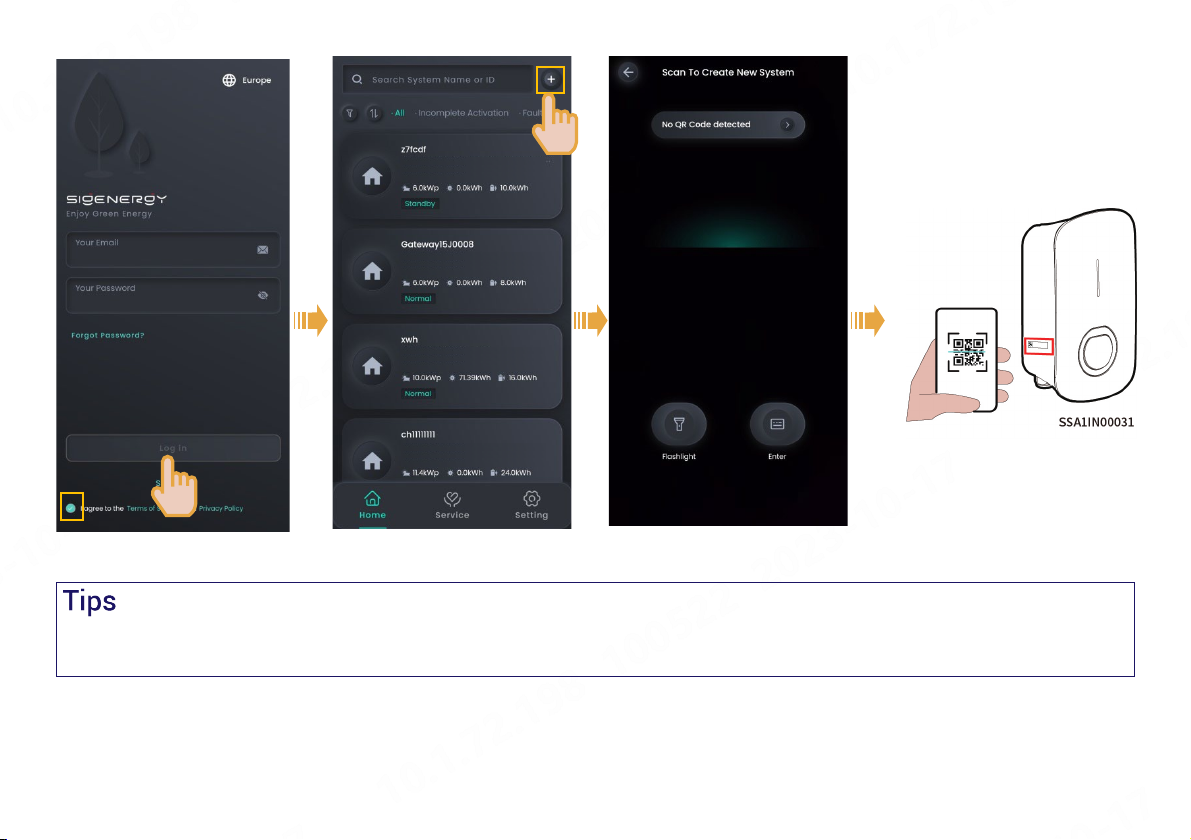
6 Power-on and New System Creation
1. Turn on the pre-AC switch.
2. Observe the indicator status on the front panel of Sigen EVAC to understand the operating conditions.
3. When the indicator turns green and is steady on or breathing blinking, create a new system in the mySigen app.
Illuminated Indicator Color Status Meaning
All Multicolored Steady on Starting, initializing configuration.
1Steady on In standby mode. Not connected to the internet, charging connector not
inserted into the vehicle.
1Breathing blink In standby mode. Connected to the internet, charging connector not inserted
into the vehicle.
All Steady on •RFID card not read. The charging connector is connected to the vehicle.
•Charging completed.
All Breathing blink You have registered the charging time, and the charging connector has
already been connected to your vehicle.
All Blink RFID card read. Get ready to charge vehicles.
All Flowing blink Charging.
None - - Not powered on or low voltage.
1Blink Equipment electrical leakage.
1Steady on Relays within the equipment getting stuck.
2Blink Overvoltage or undervoltage protection.
3Blink Overcurrent protection.
4Blink Overtemperature protection.
5Blink Grounding fault.
6Blink Communication failure between the equipment and the vehicle.
All Blink Other malfunctions.

19
The following steps are different when the equipment has already been connected or not connected to the internet (that is, FE and 4G communication
fault), as described below.
This manual suits for next models
5
Table of contents
Popular Batteries Charger manuals by other brands


WATSON
WATSON AC/DC Compact Charger owner's manual

Coleman
Coleman 6 Watt solar battery trickle charger user manual

Dynamite
Dynamite Passport UltraDuo DYN4300 instruction manual

Erbauer
Erbauer ERB607CHR Original instructions

Outback Power Systems
Outback Power Systems FX Series installation guide

ring
ring SmartCharge RSC701 instructions


