Sigenergy SigenStor EC 3.0 SP User manual

1 / 33
SigenStor Home
User Manual
Single-phase System
A1
Version: 01
Release date: 2023-07-31
2 / 33
Copyright Notice
Copyright© 2023 Sigenergy Technology Co., Ltd. All Rights Reserved.
Description in this document may contain predictive statements regarding
financial and operating results, product portfolio, new technology,
configurations and features of product. Several factors could cause difference
between actual results and those expressed or implied in the predictive
statements. Therefore, description in this document is provided for reference
purpose only and constitutes neither an offer nor an acceptance. Sigenergy
Technology Co., Ltd. may change the information at any time without notice.
and other Sigenergy trademarks are owned by
Sigenergy Technology Co., Ltd.
All trademarks and registered trademarks in this document belong to their
owners.
www.sigenergy.com
3 / 33
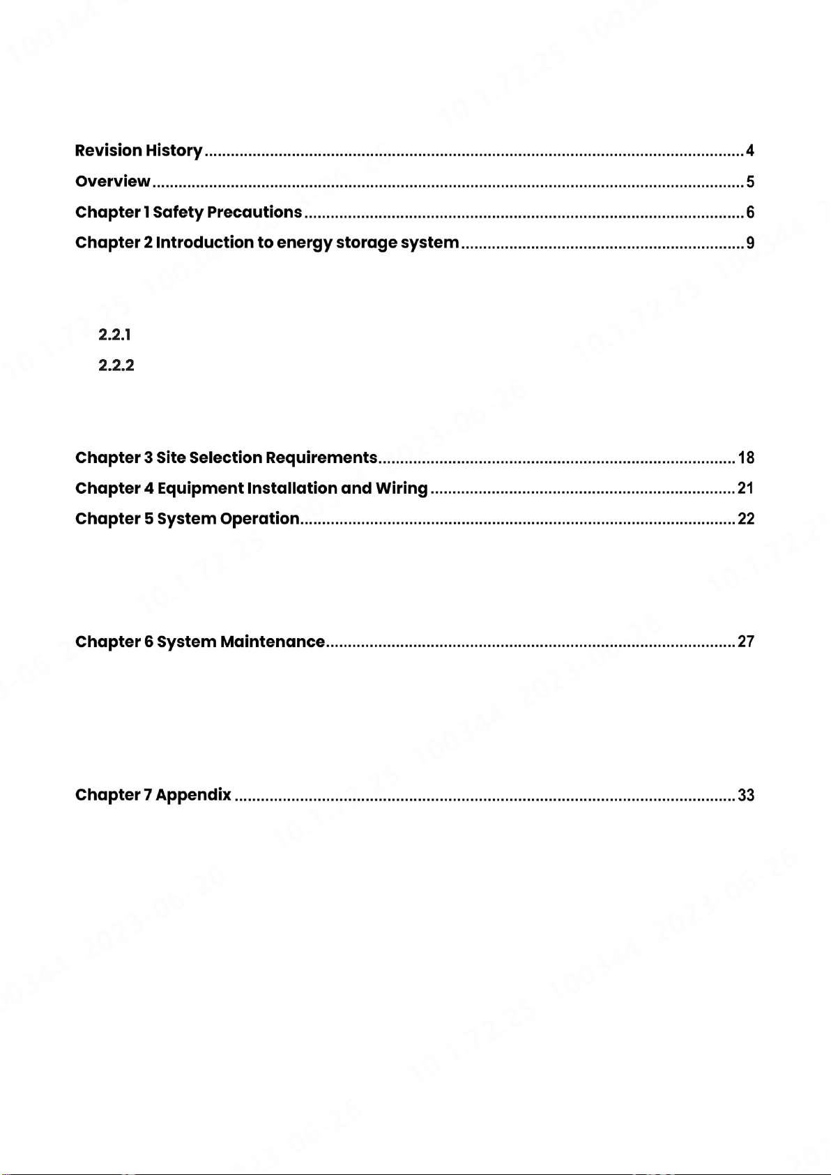
Contents
2.1 Product Introduction.............................................................................................................9
2.2 Appearance Introduction..................................................................................................12
Appearance and Dimensions .....................................................................................12
Port Introduction ..........................................................................................................13
2.3 Label Description................................................................................................................14
2.4 Introduction to Typical Networking..................................................................................15
5.1 Working Mode......................................................................................................................22
5.2 LED Indicator State .............................................................................................................24
5.3 mySigen App Query...........................................................................................................26
6.1 Routine Maintenance .........................................................................................................27
6.2 Equipment Powering-on/Power-off ................................................................................28
6.3 Low SOC...............................................................................................................................30
6.4 Emergency Treatment ......................................................................................................31
7.1 Technical Parameter ..........................................................................................................33

4/ 33
User Manual
Revision History
Version
Date
Description
01
2023.07.31
First official release.

5/ 33
User Manual
Overview
Introduction
This document mainly introduces the product introduction, networking,
system operation and maintenance of the devices in the SigenStor Home
single-phase system.
Readers
This document is suitable for product users and professionals
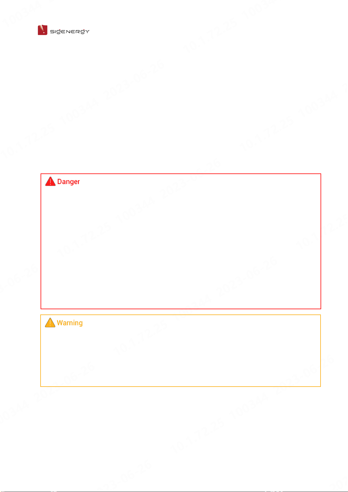
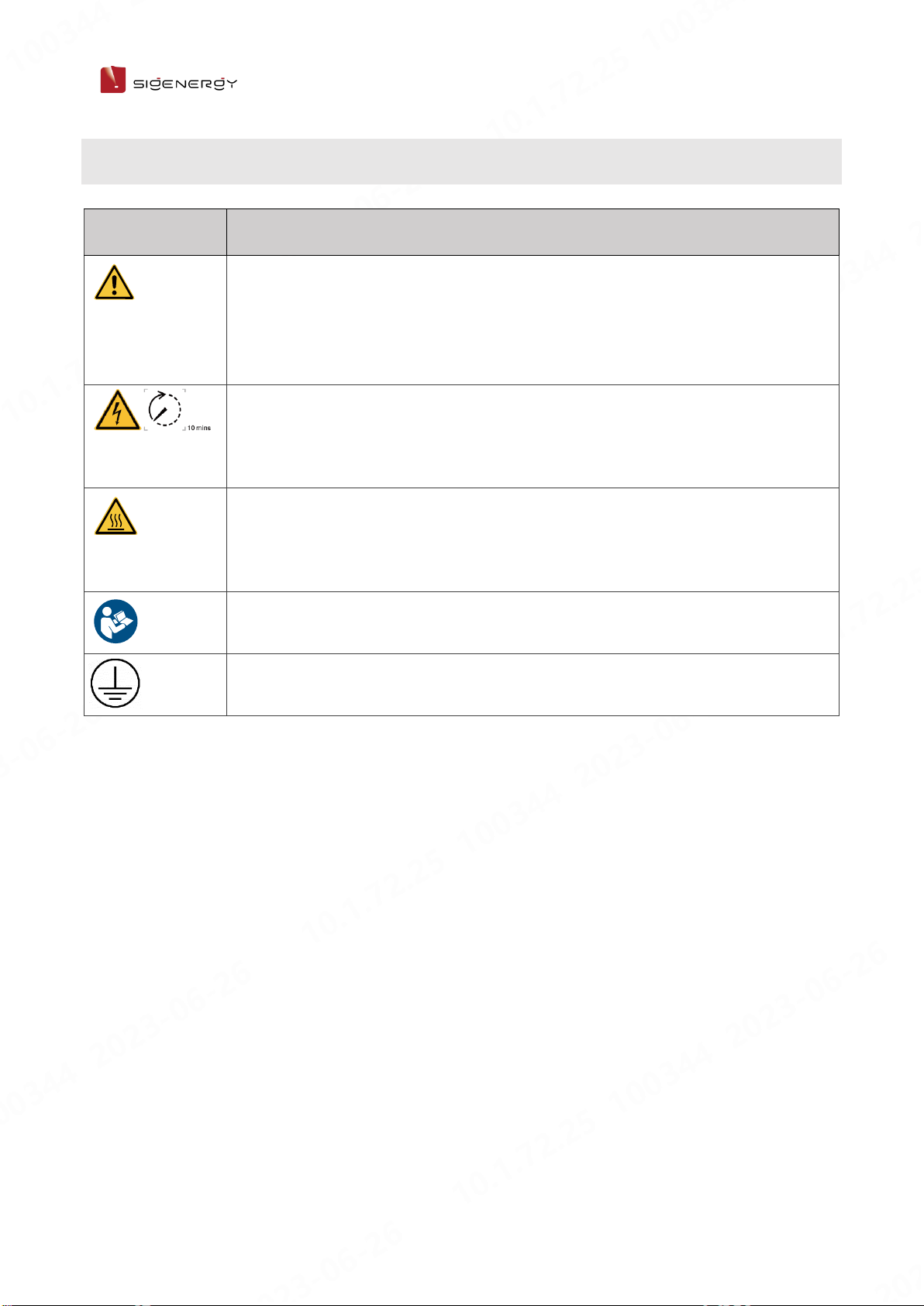
Sign Definition
The following signs may be used in the document to indicate security
precautions or key information. Before installation and operation, familiarize
yourself with signs and their definitions.
Signs
Definition
Danger. Failure to comply may result in death or
serious personal injury.
Danger. Failure to comply may result in serious
personal injury or property damage.
Caution. Failure to comply will result in property
damage.
Important or key information, and supplementary
operation tips.

6/ 33
User Manual
Safety Precautions
Basic Information
Before installing, operating, and maintaining the equipment, familiarize
yourself with this document.
The "Danger ", "Warning", "Caution" items described in this manual are only
supplementary to all precautions.
The Company shall not be liable for equipment damage or property loss
caused by the following reasons:
⚫Failure to obtain approval from the national, regional power authority.
⚫The installation environment does not meet international, national, or
regional standards.
⚫Failure to observe local laws, regulations and norms when operating and
maintaining equipment.
⚫The installation area does not meet the requirements of the equipment.
⚫Failure to follow the instructions and precautions in this document.
⚫Failure to follow the warning labels on equipment or tools.
⚫Negligent, improper operation or intentional damage.
⚫Battery capacity loss or irreversible damage caused by your failure to
charge the device in time.
⚫Damage caused by your or a third party's replacement of our equipment
(such as mixing our battery pack with other batteries, using our battery
pack with other brands of inverters or converters, etc.).
⚫The equipment is damaged by your or the third-party company to use
the accessories supplied with the package and purchase and use the
accessories of the same specifications for installation.
⚫Equipment damage caused by improper operations such as
disassembling, replacing, or modifying the software code without
authorization.
7/ 33
User Manual
⚫Equipment damage caused by force majeure (such as war,
earthquake, fire, storm, lightning, flood, debris flow, etc.).
⚫Damage caused by the failure of the natural environment or external
power parameters to meet the standard requirements of the equipment
during actual operation (for example, the actual operating temperature
of the equipment is too high or too low).
⚫The equipment was stolen.
⚫The equipment is damaged after the warranty period.
Safety Requirements
⚫The overheated battery pack may cause fire or explosion. Do not expose
the device to high temperature or heat sources (such as sunlight, fire, or
heaters) around the equipment for a long time.
⚫Do not clean or soak the equipment with water, alcohol, or oil to avoid
power leakage or battery pack leakage.
⚫Do not knock or impact the equipment. In case of an accident, please
stop using the equipment immediately and contact your sales agent, The
equipment shall be inspected and evaluated by professional personnel
before continuing to use.
⚫Do not touch the heat sink when the equipment is running.
⚫When the equipment is running, do not cover the decorative cover plate
and keep the heat dissipation channel of 300-600 mm to avoid fire at
high temperature.

8/ 33
User Manual
⚫Do not use the equipment with faults. If the equipment appears abnormal
(for example, battery pack leakage or appearance distortion), contact
your sales agent.
⚫Carbon dioxide fire extinguishers and ABC dry powder fire extinguishers
are recommended at home.
⚫If the equipment cannot be charged, please contact your sales agent in
time.
Do not use the equipment in the following situations:
⚫When connected to public infrastructure systems.
⚫When connected to emergency medical equipment.
⚫When connected to elevators and other control devices.
⚫Any other critical systems.

9/ 33
User Manual
Introduction to
energy storage system
2.1 Product Introduction
Inverter
Product
code
Model No.
Name
Function
specification
SigenStor
EC
SigenStor EC 3.0 SP
Sigen Energy Controller
3.0 kW Single Phase
Inverter; it can be
used in
photovoltaic
energy storage
scenarios and
needs to be used
together with PV
modules and
SigenStor BAT.
SigenStor EC 3.6 SP
Sigen Energy Controller
3.6 kW Single Phase
SigenStor EC 4.0 SP
Sigen Energy Controller
4.0 kW Single Phase
SigenStor EC 4.6 SP
Sigen Energy Controller
4.6 kW Single Phase
SigenStor EC 5.0 SP
Sigen Energy Controller
5.0 kW Single Phase
SigenStor EC 6.0 SP
Sigen Energy Controller
6.0 kW Single Phase
SigenStor
AC
SigenStor AC 3.0 SP
Sigen Storage Controller
3.0 kW Single Phase
Inverter; it can be
used in pure
storage scenarios
and needs to be
used with
SigenStor BAT.
SigenStor AC 3.6 SP
Sigen Storage Controller
3.6 kW Single Phase
SigenStor AC 4.0 SP
Sigen Storage Controller
4.0 kW Single Phase
SigenStor AC 4.6 SP
Sigen Storage Controller
4.6 kW Single Phase
SigenStor AC 5.0 SP
Sigen Storage Controller
5.0 kW Single Phase
SigenStor AC 6.0 SP
Sigen Storage Controller
6.0 kW Single Phase

10 / 33
User Manual
Sigen
Hybrid
Sigen Hybrid 3.0 SP
Sigen Hybrid Inverter 3.0
kW Single Phase
Inverter; it can be
used in
conjunction with
PV modules for
pure PV
applications or in
combination with
PV modules and
SigenStor BAT for
photovoltaic
storage systems
after the purchase
and activation of
a license.
Sigen Hybrid 3.6 SP
Sigen Hybrid Inverter 3.6
kW Single Phase
Sigen Hybrid 4.0 SP
Sigen Hybrid Inverter 4.0
kW Single Phase
Sigen Hybrid 4.6 SP
Sigen Hybrid Inverter 4.6
kW Single Phase
Sigen Hybrid 5.0 SP
Sigen Hybrid Inverter 5.0
kW Single Phase
Sigen Hybrid 6.0 SP
Sigen Hybrid Inverter 6.0
kW Single Phase
Battery Pack
Product
code
Model No.
Name
Function
specification
SigenStor
BAT
SigenStor BAT 5.0
Sigen Battery 5 kWh
It can store electric
energy.
SigenStor BAT 8.0
Sigen Battery 8 kWh
Power Sensor
Product
code
Model No.
Name
Function
specification
Power
Sensor
Sigen Sensor
SP-DH(SDM230MODBUS)
Sigen Power Sensor
Single Phase DH
Data acquisition
for grid
connection points
enables
zero-power grid
connection.
Sigen Sensor
SP-CT-DH(SDM120CTM)
Sigen Power Sensor
Single Phase
External CT DH

11 / 33
User Manual
Communication Module
Product
code
Model No.
Name
Function
specification
CommMod
Sigen CommMod
Sigen Communication
Module
If it's used with our
inverters, the
communication
between inverters
and management
systems should be
realized through
4G.
12 / 33
User Manual
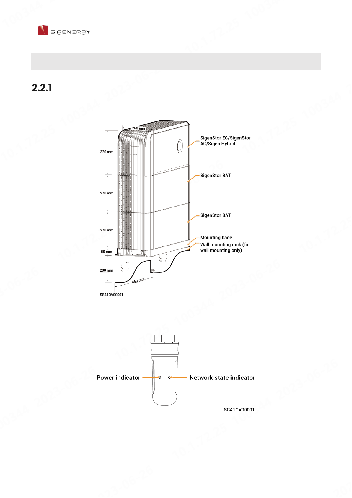
2.2 Appearance Introduction
Appearance and Dimensions
Inverter and Battery Pack
CommMod

13 / 33
User Manual
Port Introduction
SigenStor EC/ SigenStor AC/Sigen Hybrid Left View
S/N
Name
Marking
1
Dc switch
DC SWITCH
2
Decorative cover light strip connector
LED
3
Antenna interface
ANT
4
Cable interface
RJ45 1/ RJ45 2
5
AC output interface
AC
6
Ground screw
-
7
Communication interface
COM
8
Sigen CommMod interface
4G
9
DC input interface
PV1+/PV2+/ PV1-/PV2-
10
Switch button
ON/OFF
14 / 33
User Manual
2.3 Label Description
Symbols
Definition
Warning! Life at risk.
The equipment has potential hazards after running. Take proper
protection when operating the equipment.
After the equipment is powered off, the discharge of internal
components is delayed. Wait 10 minutes until the equipment is
fully discharged according to the label time.
Warning! Risk of burns.
The equipment surface is hot. Do not touch the inverter when it
is running. Doing so may result in burns.
Please refer to the instructions to operate the equipment.
Earthing mark
15 / 33
User Manual
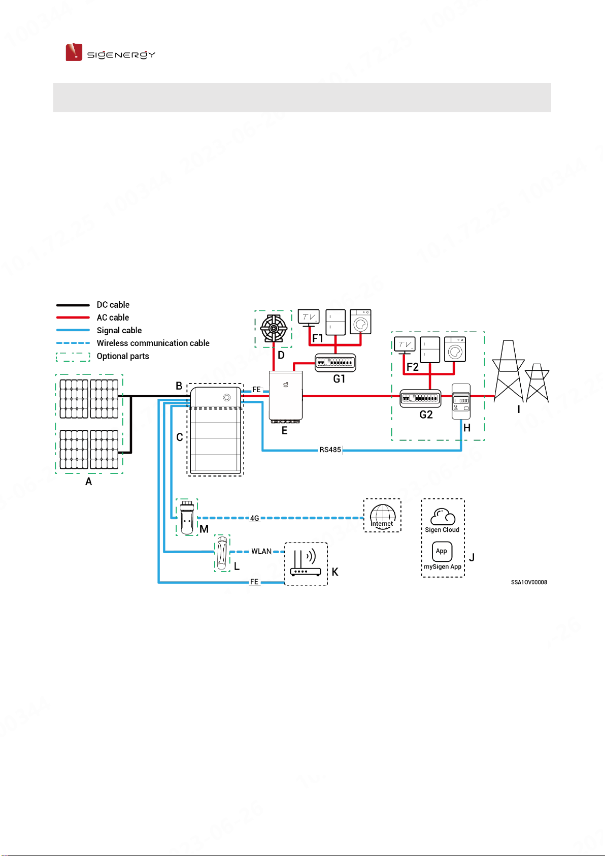
2.4 Introduction to Typical Networking
⚫The SigenStor Home energy storage system consists of photovoltaic panels,
inverters, battery packs, master control switches, loads, power grids, etc.
⚫The main function of SigenStor Home energy storage system is to store the
direct current generated by photovoltaic panels into battery packs. Or
alternatively, the electricity in the photovoltaic system and the battery pack
can be converted into alternating current for use by the load or incorporated
into the grid.
Networking Diagram (Backup Networking)
A
PV panel
B
SigenStor EC/ SigenStor AC/Sigen Hybrid
C
SigenStor BAT
D
Diesel generator
E
Gateway
F1
Backup electric equipment
F2
Non-backup electric
equipment
G1
Backup distribution panel
G2
Non-backup
distribution panel
H
Power Sensor
I
Power Grid

16 / 33
User Manual
⚫When B is SigenStor AC, A is not configured.
⚫In case of home-wide backup, F2, G2, and H are not configured; for partial
backup, H can be left un-configured; in case of partial backup +
zero-power grid connection control, F2, G2, and H are configured.
⚫As a backup energy source for long-term off-grid applications, the diesel
generator can work in tandem with the Gateway to provide a smooth
transition between PV, storage and diesel power generation.
⚫It is recommended to use FE and WLAN for communication with inverter.
CommMod users must top up their own 4G data plan after a period of 2
years.
Networking Diagram (Non-backup Networking)
17 / 33
User Manual
A
PV panel
B
SigenStor EC/ SigenStor AC/Sigen Hybrid
C
SigenStor BAT
D
Electric
E
Distribution panel
F
Power sensor
G
Power grid
H
mySigen
I
Router
J
Antenna
K
CommMod
⚫When B is SigenStor AC, A is not configured.
⚫When B is Sigen Hybrid, A is optional.
⚫It is recommended to use FE and WLAN for communication with inverter.
CommMod users must top up their own 4G data plan after a period of 2
years.
⚫The rated voltage of the AC switch connected to each inverter should be ≥
240 V AC and the rated current is recommended:
➢SigenStor EC/SigenStor AC/Sigen Hybrid (3.0-4.0) SP: The rated current is
25 A
➢SigenStor EC/SigenStor AC/Sigen Hybrid (4.6-6.0) SP: The rated current is
40 A

18 / 33
User Manual
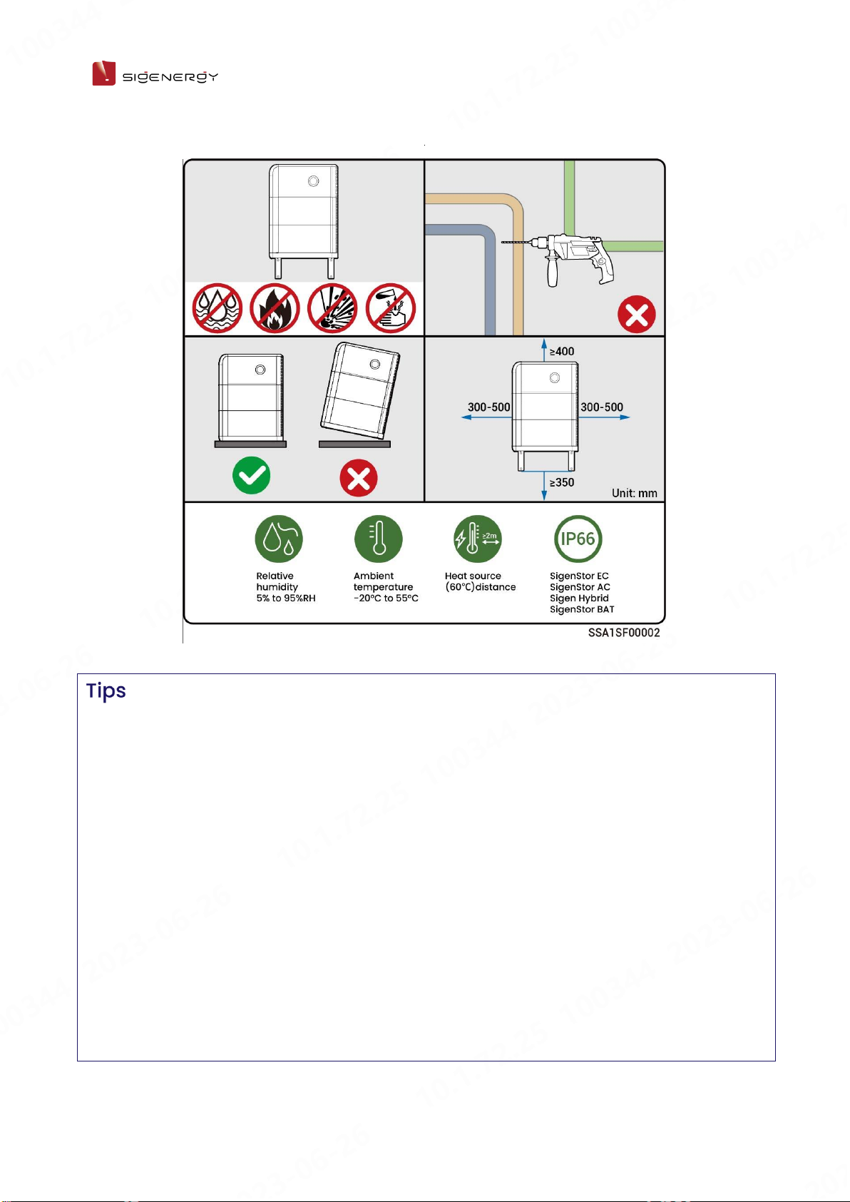
Site Selection
Requirements
Installation Environment Requirements
⚫Do not install the equipment in smoky, flammable, explosive, or corrosive
environments.
⚫Do not install the equipment outdoors in areas prone to salt damage
area, which are located less than 500 meters from the coastline or
affected by sea wind.
⚫Do not install the equipment in environments exposed to direct sunlight,
rain, standing water, snow accumulation, sand, and dust. It is
recommended to install in a sheltered location. If the area is susceptible
to natural disasters such as floods, landslides, earthquakes, or typhoons,
take preventive measures during equipment installation.
⚫Do not install the equipment in environments with electromagnetic
interference.
⚫Ensure that the temperature and humidity of the installation environment
comply with the equipment's requirements.
Installation Position Requirements
⚫Do not tilt or overturn the equipment to ensure that it is installed
horizontally.
⚫Do not install the equipment in a place where children can easily reach it.
⚫Do not install the equipment in areas subject to fire or moisture (including
but not limited to kitchen, tea room, toilet, shower room, laundry room,
etc.).
⚫Please keep away from daily working and living areas (including but not
limited to living room, bedroom, studio, lounge, study, etc.).
⚫Do not install the equipment in areas that are difficult to access
(including but not limited to attic, basement, etc.).

19 / 33
User Manual
⚫Do not install the equipment in mobile scenarios such as
RVS, cruise ships, and trains.
⚫You are advised to install the equipment in a position that is easy to
operate, maintain, and view indicator status.
⚫When installing the equipment in the garage, do not install the equipment
in the position where the vehicle passes through to avoid collision.
Mounting Surface Requirements
⚫Do not install the equipment on a flammable carrier.
⚫The installation carrier must meet load-bearing requirements. Solid
brick-concrete structure, concrete walls, and ground are recommended.
⚫The surface of the installation carrier must be smooth and the installation
area must meet the installation space requirements.
⚫No water or electricity is routed inside the carrier to prevent drilling
hazards during equipment installation.
20 / 33
User Manual
⚫The maximum operating temperature range applicable to the equipment is
-20°C to 55°C, and the recommended optimal operating temperature range
is 10°C < T < 35°C.
⚫When the battery pack temperature is below 0°C, immediate charging is not
possible, and the battery pack (the built-in heating module can be
automatically enabled) will activate the heating feature automatically. The
best charging performance of the battery can be achieved after heating for
less than 2 h. The heating feature will consume power.
⚫At a temperature > 40°C, the operation of the equipment may trigger a
power derating that prevents the equipment from operating optimally. The
higher the temperature, the shorter the service life of the equipment.
This manual suits for next models
17
Table of contents
Other Sigenergy Storage manuals

Popular Storage manuals by other brands
Arrow Storage Products
Arrow Storage Products IWA1012 Owner's manual & assembly guide

NetApp
NetApp StorageGRID Webscale SG5700 Series Install

Hama
Hama usb cf card operating instructions

Newer Technology
Newer Technology Guardian Maximus Assembly manual & user guide

Seagate
Seagate BARRACUDA 18FC installation guide

G-Technology
G-Technology G-DRIVE mobile USB manual


Western Digital
Western Digital My Book 3.0 WDBAAK0020HCH Product specifications

Herrnhuter
Herrnhuter storage box Assembly instruction

LaCie
LaCie Hard Drive Quick install guide

Western Digital
Western Digital WDXUB3200JB - Dual-Option USB install guide

Oracle
Oracle 7087210 instructions

HP
HP P700 quick start guide