Sigenergy SigenStor Checkwatt CM10 User manual
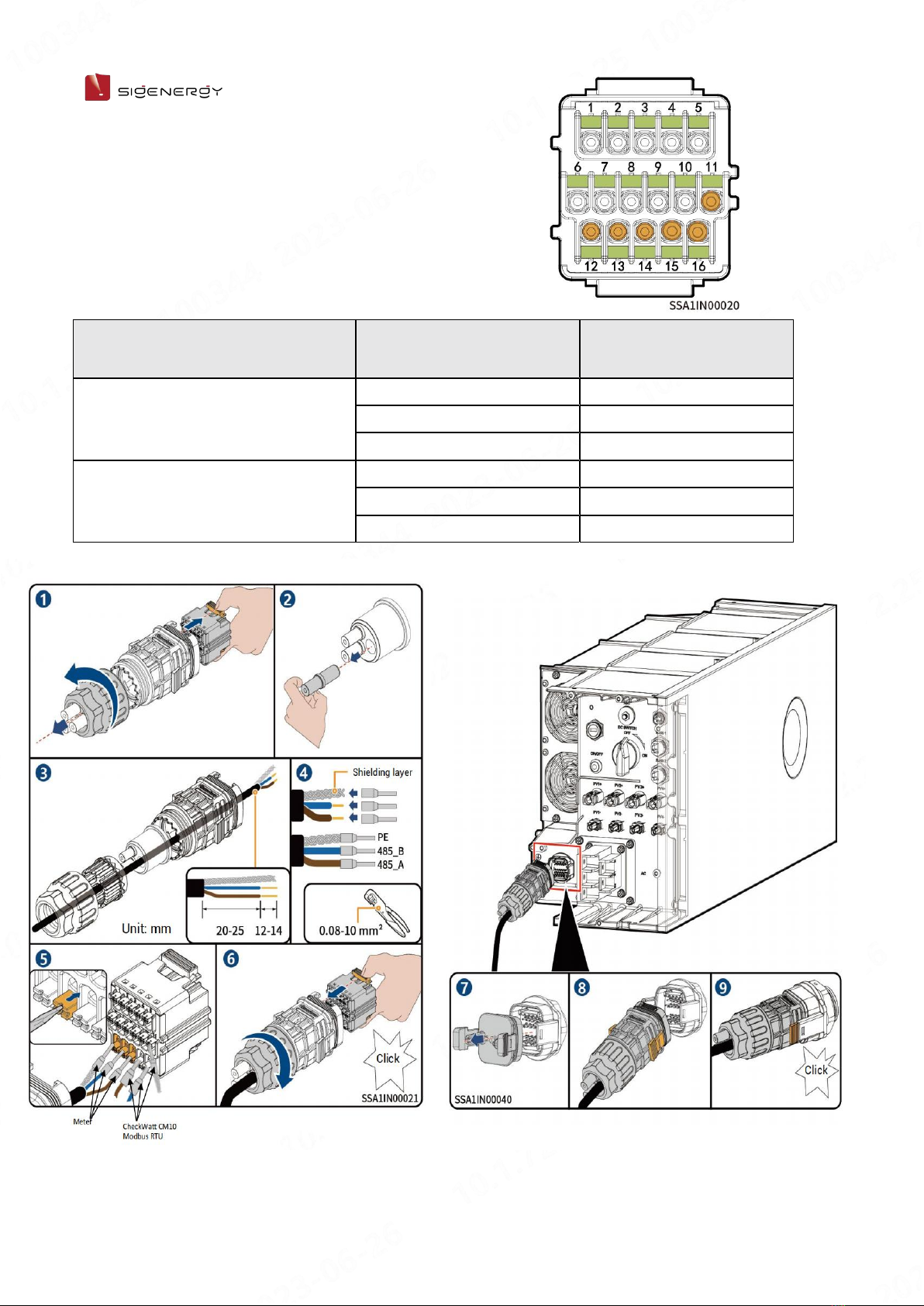
1/17
SigenStor Home Install with
Checkwatt CM10 Guide
Release date: 2023-12-08
For Aprilice Installers
Three-phase System
A1

2/17
Copyright Notice
Copyright© 2023 Sigenergy Technology Co., Ltd. All Rights Reserved.
Description in this document may contain predictive statements regarding
financial and operating results, product portfolio, new technology,
configurations and features of product. Several factors could cause difference
between actual results and those expressed or implied in the predictive
statements. Therefore, description in this document is provided for reference
purpose only and constitutes neither an offer nor an acceptance. Sigenergy
Technology Co., Ltd. may change the information at any time without notice.
and other Sigenergy trademarks are owned by
Sigenergy Technology Co., Ltd.
All trademarks and registered trademarks in this document belong to their
owners.
www.sigenergy.com

3/17
Contents
Overview..............................................................................................................................................4
Chapter 1 Safety Precautions......................................................................................................... 5
Chapter 2 Introduction to energy storage system....................................................................8
2.1 Appearance Introduction.........................................................................................................8
2.1.1 Appearance and Dimensions............................................................................................. 8
2.1.2 Port Introduction....................................................................................................................9
Chapter 3 Equipment Installation and Wiring......................................................................... 10
Chapter 4 System Operation........................................................................................................15
4.1 mySigen App Download.........................................................................................................15
4.2 mySigen App Setting for Modbus Control......................................................................... 15

4/17
User Manual
Overview
Introduction
This document mainly introduces the product introduction, networking, system
operation and maintenance of the devices in the SigenStor Home Three-phase
system.
Readers
This document is suitable for product users and professionals
Sign Definition
The following signs may be used in the document to indicate security
precautions or key information. Before installation and operation, familiarize
yourself with signs and their definitions.
Signs
Definition
Danger. Failure to comply may result in death or serious
personal injury.
Danger. Failure to comply may result in serious personal
injury or property damage.
Caution. Failure to comply may result in property damage.
Important or key information, and supplementary
operation tips.

5/17
User Manual
Chapter 1 Safety Precautions
Basic Information
Before installing, operating, and maintaining the equipment, familiarize yourself
with this document.
The "Danger ", "Warning", "Caution" items described in this manual are only
supplementary to all precautions.
The Company shall not be liable for equipment damage or property loss caused
by the following reasons:
Failure to obtain approval from the national, regional power authority.
The installation environment does not meet international, national, or regional
standards.
Failure to observe local laws, regulations and norms when operating and
maintaining equipment.
The installation area does not meet the requirements of the equipment.
Failure to follow the instructions and precautions in this document.
Failure to follow the warning labels on equipment or tools.
Negligent, improper operation or intentional damage.
Battery capacity loss or irreversible damage caused by your failure to charge
the device in time.
Damage caused by your or a third party's replacement of our equipment
(such as mixing our battery pack with other batteries, using our battery
pack with other brands of inverters or converters, etc.).
The equipment is damaged by your or the third-party company to use the
accessories supplied with the package and purchase and use the
accessories of the same specifications for installation.
Equipment damage caused by improper operations such as disassembling,
replacing, or modifying the software code without authorization.
Equipment damage caused by force majeure (such as war, earthquake, fire,

6/17
User Manual
storm, lightning, flood, debris flow, etc.).
Damage caused by the failure of the natural environment or external power
parameters to meet the standard requirements of the equipment during
actual operation (for example, the actual operating temperature of the
equipment is too high or too low).
The equipment was stolen.
The equipment is damaged after the warranty period.
Safety Requirements
An overheated battery pack may cause fire or explosion. Do not expose the
device to high temperature or heat sources (such as fire, or heaters)
around the equipment for a long time.
Do not clean or soak the equipment with water, alcohol, or oil to avoid power
leakage or battery pack leakage.
Do not tipover or cause impact to the equipment. In case of an accident,
please stop using the equipment immediately and contact your installer,
The equipment shall be inspected and evaluated by professional
personnel before continuing to use.
Do not touch the heat sink when the equipment is operating.
When the equipment is operating, do not cover the decorative cover plate
and keep the heat dissipation channel of 300–600 mm to avoid fire at high
temperature.

7/17
User Manual
Do not use the equipment if it has any defects. If the equipment appears
abnormal (for example, battery pack leakage or appearance distortion),
contact your installer.
Carbon dioxide fire extinguishers and ABC dry powder fire extinguishers are
recommended at home.
If the equipment cannot be charged, please contact your installer in time.
Do not use the equipment in the following situations:
When connected to public infrastructure systems.
When connected to emergency medical equipment.
When connected to elevators and other control devices.
Any other critical systems.

8/17
User Manual
Chapter 2 Introduction to energy
storage system
2.1 Appearance Introduction
2.1.1 Appearance and Dimensions
Inverter and Battery Pack

9/17
User Manual
2.1.2 Port Introduction
SigenStor EC/ SigenStor AC/Sigen Hybrid Left View
S/N
Name
Marking
1
Decorative cover light strip connector
LED
2
Network interface
RJ45 1/ RJ45 2
3
DC input interface
PV1+/PV2+/ PV3+/PV4+/
PV1-/PV2- /PV3-/PV4-
4
AC output interface
AC
5
Communication interface
COM
6
Ground screw
-
7
Switch button
ON/OFF
8
DC switch
DC SWITCH
9
Sigen CommMod interface
4G
10
Antenna interface
ANT

10 /17
User Manual
Chapter 3 Equipment Installation
and Wiring
Only company authorized personnel should install and connect the equipment.
For details, see SigenStor Home Installation Guide - Three-phase System A1.
Below is the networking figure for Modbus RTU mode with Checkwatt CM10
device using RS485.
The RS485 cable from SigenStor,has three wires, among which RS485A1 should
be connected to the + port of the Checkwatt device, RS485B1 should be
connected to the - port of the Checkwatt device and the PE line should be
connected to the GND port.
Please also refer to the wiring detail figure on page 14.

11 /17
User Manual
Below is the networking figure for Modbus TCP mode with Checkwatt CM10
device using FE cable.
The FE cable connecting the SigenStor should be plug in the checkwatt CM10 LAN2.
And the LAN1 of Checkwatt CM10 should be plug in to the router.

12 /17
User Manual
S/N
Equipment/compon
ent
Model/version
Function specification
A
PV module
-
-
B
SigenStor EC
SigenStor EC 5.0/6.0/8.0/10.0
/12.0/15.0/17.0/20.0/25.0 TP
Inverter; it can be used in photovoltaic energy storage scenarios and needs
to be used together with PV modules and SigenStor BAT.
SigenStor AC
SigenStor AC 5.0/6.0/8.0/10.0
/12.0/15.0/17.0/20.0/25.0 TP
Inverter; it can be used in pure storage scenarios and needs to be used with
SigenStor BAT.
Sigen Hybrid
Sigen Hybrid 5.0/6.0/8.0/10.0
/12.0/15.0/17.0/20.0/25.0 TP
Inverter; it can be used in conjunction with PV modules for pure PV applicat
ions or in combination with PV modules and SigenStor BAT for photovoltaic
storage systems after the purchase and activation of a license.
C
SigenStor BAT
SigenStor BAT 5.0/8.0
Battery pack; it can store electric energy.
D
Diesel generator
-
As a backup energy source for long-term off-grid applications, it can work i
n tandem with the Gateway to provide a smooth transition between PV, stor
age and diesel generation.
E
Gateway
Sigen Gateway HomeMax TP
It's applicable for PV storage and pure storage applications to facilitate dat
a acquisition and monitoring, off-grid backup power switching, diesel gener
ator control, energy management; it must be used with SigenStor BAT and i
nverter. Gateway is a must-have for backup networking; for partial backup
power and zero-power grid connection control networking, the Gateway an
d power sensor must be arranged.
F
Electric equipment
-
In the backup networking, F1 is the electric equipment for backup; F2 is non
-backup the electric equipment.
G
Distribution panel
-
In the backup networking, G1 is the backup Distribution panel; G2 is the non
-backup Distribution panel.
The rated voltage of the AC switch connected to each inverter should be ≥ 3
80 Va.c, and the rated current is recommended:
SigenStor EC/SigenStor AC/Sigen Hybrid (5.0–8.0) TP: The rated current is
20 A
SigenStor EC/SigenStor AC/Sigen Hybrid (10.0–15.0) TP: The rated current
is 32 A
SigenStor EC/SigenStor AC/Sigen Hybrid (17.0–20.0) TP: The rated current
is 40 A
SigenStor EC/SigenStor AC/Sigen Hybrid 25.0 TP:The rated current is 50 A

13 /17
User Manual
S/N
Equipment/compon
ent
Model/version
Function specification
H
Power sensor
Sigen Sensor TP-DH
(SDM630MODBUS V2)
Sigen Sensor TP-CT120-DH
(SDM630MCT 40mA/120A)
Sigen Sensor TP-CT300-DH
(SDM630MCT 40mA/300A)
Sigen Sensor TP-CT600-DH
(SDM630MCT V2/600A)
Data acquisition for grid connection points enables zero-power grid connec
tion.
I
Power grid
-
-
J
App
mySigen
Android 6.0 or later
iOS 12.0 onwards
K
Router
-
To be used for FE/WLAN communication.
L
Antenna
-
To be used for WLAN communication.
M
Communication mo
dule
Sigen CommMod
To be used for 4G communication.

14 /17
User Manual
RS485 wiring detailed figure
Description
Interface definition
COM terminal of the inverter
COM port used to access the power sensor
PE signal shielding ground
12
RS485 signal 2_B-
13
RS485 signal 2_A+
14
Modbus RS485 port
PE signal shielding ground
11
RS485 signal 1_A+
15
RS485 signal 1_B-
16

15 /17
User Manual
Chapter 4 System Operation
4.1 mySigen App Download
The App can be downloaded in the following two ways. For details, see mySigen
App User Manual.
4.2 mySigen App Setting for Modbus Control
1. Setting System Remote EMS enable:
This step is obligatorily for both Modbus RTU and Modbus TCP.
In System panel, click on behind the station name , and then click on System Settings.

16 /17
User Manual
In the System Settings panel, turn on the Remote EMS Scheduling Enable button. It is
enabled, when the button is green, and disabled when the button is gray. Remember to click
the Save button on the right corner.

17 /17
User Manual
2. Setting Modbus TCP server enable:
To enable the Modbus TCP mode, this step must be performed in addition to step 1.
No need for Modbus RTU mode if you only intend to use RTU mode.
Click the Device button to switch to Device panel. Click on the SigenStor Settings button, and
go into the SigenStor Settings panel.
Turn on the Modbus TCP Server Enable button, and click on the Save button on the right.
Table of contents
Other Sigenergy Storage manuals