Sigineer Power M3024NC User manual


www.sigineer.com
2
Table of Contents
1 Important Safety Information ................................................................................................................................................. 3
1.1 General Safety Precautions.................................................................................................................................................. 3
1.2 Precautions When Working with Batteries.......................................................................................................................... 4
1.3 Target Group ....................................................................................................................................................................... 4
2 Introduction ............................................................................................................................................................................ 4
2.1 General Information ............................................................................................................................................................ 4
2.2 Mechanical Design .............................................................................................................................................................. 5
2.3 Features ............................................................................................................................................................................... 6
2.4 Electrical Performance ........................................................................................................................................................ 6
2.4.1 DC to AC Invert........................................................................................................................................................ 6
2.4.2 AC & MPPT Charger................................................................................................................................................ 6
2.4.3 DC&AC Transfer...................................................................................................................................................... 9
2.4.4 Power Saver.............................................................................................................................................................. 9
2.4.5 Protections .............................................................................................................................................................. 10
2.4.6 Remote Monitoring ................................................................................................................................................ 10
2.4.7 LCD & Specification Setup.................................................................................................................................... 12
2.4.8 Audible Alarm ........................................................................................................................................................ 26
2.4.9 FAN Operation ....................................................................................................................................................... 26
2.4.10 Auto Generator Start Dry Contact ........................................................................................................................ 26
2.4.11 Automatic Recovery Operation ............................................................................................................................ 27
2.4.12 Lithium Battery Wakeup....................................................................................................................................... 27
2.4.13 Other Features ...................................................................................................................................................... 27
3 Installation ............................................................................................................................................................................ 27
3.1 Location..................................................................................................................................................................... 27
3.2 Unpacking and Inspection ......................................................................................................................................... 28
3.3 Battery Wiring ........................................................................................................................................................... 29
3.4 PV Wiring.................................................................................................................................................................. 31
3.5 AC Wiring.................................................................................................................................................................. 32
3.6 Communication With Lithium Batteries ................................................................................................................... 33
3.7 Inverter Parallel Operation ................................................................................................................................................ 35
3.7.1 Parallel in Single Phase to Expand Power.............................................................................................................. 35
3.7.2 Parallel To Form Three Phase................................................................................................................................. 38
3.7.3 Parallel to Form Split Phase ................................................................................................................................... 42
3.7.4 LCD Setting For Parallel Operation ....................................................................................................................... 43
3.8 Communication With Computer ............................................................................................................................... 45
3.9 Grounding.................................................................................................................................................................. 46
4 Maintenance & Troubleshooting.......................................................................................................................................... 47
5 Warranty............................................................................................................................................................................... 51
Appendix 1 : M 3KW Solar Inverter Spec Sheet .................................................................................................................... 52
Please record the Sigineer Power unit’s model and serial number in case you need to provide this
information in the future. It is much easier to record this information now than try to gather it after
the unit has been installed.
Order Number:
Model Number:
Serial Number:
www.sigineer.com
3
1 Important Safety Information
Save This Manual! Read this manual before installation, it contains important safety, installation
and operating instructions. Keep it in a safe place for future reference.
All wiring must follow the National Electric Code, Provincial or other codes in effect at the time
of installation, regardless of suggestions in this manual. This off grid solar inverter should be
connected to a grounded wiring system. If the system ground is floating, please follow the codes
in effect.
MISTAKES TO AVOID
1 Don’t reverse the PV input polarity.
2 Don’t use any third-party accessories, communication cables on the inverter.
3 Don’t wire the AC input power to the AC output terminals.
4 Don’t install the inverter without AC input surge protection device (SPD)or lightning
protection.
1.1 General Safety Precautions
1.1.1 Before installing and using the M Series Off Grid Solar Inverter Charger, read the manual and
cautionary markings on the Inverter/Charger enclosure. Be sure to read all instructions and cautionary
markings for any equipment attached to this unit. Installers must be certified technicians or electricians.
1.1.2 This product is designed for indoor/compartment installation. Do not expose the inverter/charger to
rain, snow, spray, bilge or dust. To reduce the risk of hazard, do not cover or obstruct the ventilation
openings. Do not install the inverter/charger in a zero-clearance compartment. Overheating may result.
Allow at least 30CM (11.81 inches) of clearance around the inverter for air flow. Make sure that the air can
circulate freely around the unit. A minimum air flow of 145CFM is required.
1.1.3 To avoid a risk of fire and electronic shock. Make sure that existing wiring is in good electrical
condition; and that wire size is not undersized. Do not operate the Inverter with damaged or substandard
wiring.
1.1.4 This equipment contains components which can produce arcs or sparks. To prevent fire or explosion
do not install in compartments containing batteries or flammable materials or in locations which require
ignition protected equipment. This includes any space containing gasoline-powered machinery, fuel tanks,
or joints, fittings, or other connection between components of the fuel system. See Warranty for instructions
on obtaining service.
1.1.5 Do not dis-assemble the Inverter/Charger. It contains no user serviceable parts. Attempting to service
the Inverter/Charger yourself may result in a risk of electrical shock or fire. Internal capacitors remain
charged after all power is disconnected.
1.1.6 To reduce the risk of electrical shock, disconnect both AC and DC power from the Inverter/Charger
before attempting any maintenance or cleaning. Turning off controls will not reduce this risk
CAUTION: Equipment damage
The output side of the inverter’s AC wiring should at no time be connected to public power or a generator.
This condition is far worse than a short circuit. If the unit survives this condition, it will shut down until
corrections are made.
Installation should ensure that the inverter’s AC output is, at no time, connected to its AC input.
WARNING:LIMITATIONS ON USE
SPECIFICALLY, PLEASE NOTE THAT THE INVERTER/CHARGER SHOULD NOT BE USED IN
CONNECTION WITH LIFE SUPPORT SYSTEMS OR OTHER MEDICAL EQUIPMENT OR DEVICES.
WE MAKE NO WARRANTY OR REPRESENTATION IN CONNECTION WITH THEIR PRODUCTS

www.sigineer.com
4
FOR SUCH USES. USING THE INVERTER/CHARGER WITH THESE PARTICULAR EQUIPMENTS
IS AT YOUR OWN RISK.
1.2 Precautions When Working with Batteries
1.2.1 If battery acid contacts skin or clothing, wash immediately with soap and water. If acid enters eye,
immediately flood eye with running cold water for at least 20 minutes and get medical attention
immediately.
1.2.2 Never smoke or allow a spark or flame in the vicinity of battery or engine.
1.2.3 Do not drop a metal tool on the battery. The resulting spark or short-circuit on the battery of other
electrical part may cause an explosion.
1.2.4. Remove personal metal items such as rings, bracelets, necklaces, and watches when working with a
lead-acid battery. A lead-acid battery produces a short-circuit current high enough to weld a ring or the like
to metal, causing a severe burn.
1.2.5 To reduce the risk of injury, charge only rechargeable batteries accepted by our inverter such as
deep-cycle lead acid, lead antimony, lead calcium gel cell, absorbed mat, NiCad/NiFe or Lithium battery.
Other types of batteries may burst, causing personal injury and damage. NEVER charge a frozen battery.
1.2.6 Don’t install the inverter near batteries, the inverter may heat battery electrolyte and cause corrosive
fumes to vent and damage/corrode nearby electronics or metals.
1.3 Target Group
This document is intended for qualified persons and end users. Tasks that do not require any particular
qualification can also be performed by end users. Qualified persons must have the following skills:
Knowledge of how an inverter works and is operated
Training in how to deal with the dangers and risks associated with installing and using electrical devices and
installations
Training in the installation and commissioning of electrical devices and installations
Knowledge of the applicable standards and directives
Knowledge of and compliance with this document and all safety information
2 Introduction
2.1 General Information
Thank you for purchasing the M 3KW Off Grid Solar Inverter/Charger.
The M 3KW Transformerless Off Grid Solar Inverter/Charger is a combination of 4 products:
1. Transformerless DC to AC power inverter
2. AC to DC utility battery charger
3. 80A MPPT Solar Charger Controller
4. High Speed DC/AC Transfer Switch.
Packed with unique features, it is one of the most technically advanced off grid solar inverter on the market.
Some solar inverter on the market physically includes a solar charger which has no communication with the
circuit of the inverter.
www.sigineer.com
5
Our MPPT charger is electrically integrated into the inverter design and is able to harness the PV production
to charge batteries when the the inverter is powered off.
Its powerful DSP (digital signal processor) makes the M3KW solar inverter very versatile and almost all of
its specifications can be adjusted via its top cover LCD or remote LCD panel, such as AC output voltage,
frequency, power priority, low/high battery cutoff, charging profiles & amperage, DC/AC transfer voltage,
etc.
The M 3KW models are available in 24V and 48V DC input, and 120V AC output.
You can get the 120/240V split phase power or 120/208Vac by stacking them up to 6 pcs.
It supports different types of remote monitoring with Remote LCD Panel (Sold separately),Wi-Fi or GPRS
module or computer.
The BMS port communicates with lithium battery for optimal operation of batteries.
It also has a programmable “US2” setting which works with lithium batteries without BMS communication
with the inverter.
The 200% surge capacity of 5 seconds makes it possible to support demanding inductive loads.
Thus, the M Series Solar Inverter/Charger is suitable for a myriad of applications including renewable
energy systems, utility, truck, RV and emergency vehicles etc.
To get the most out of the power inverter, it must be installed, used and maintained properly. Please read the
instructions in this manual before installing and operating.
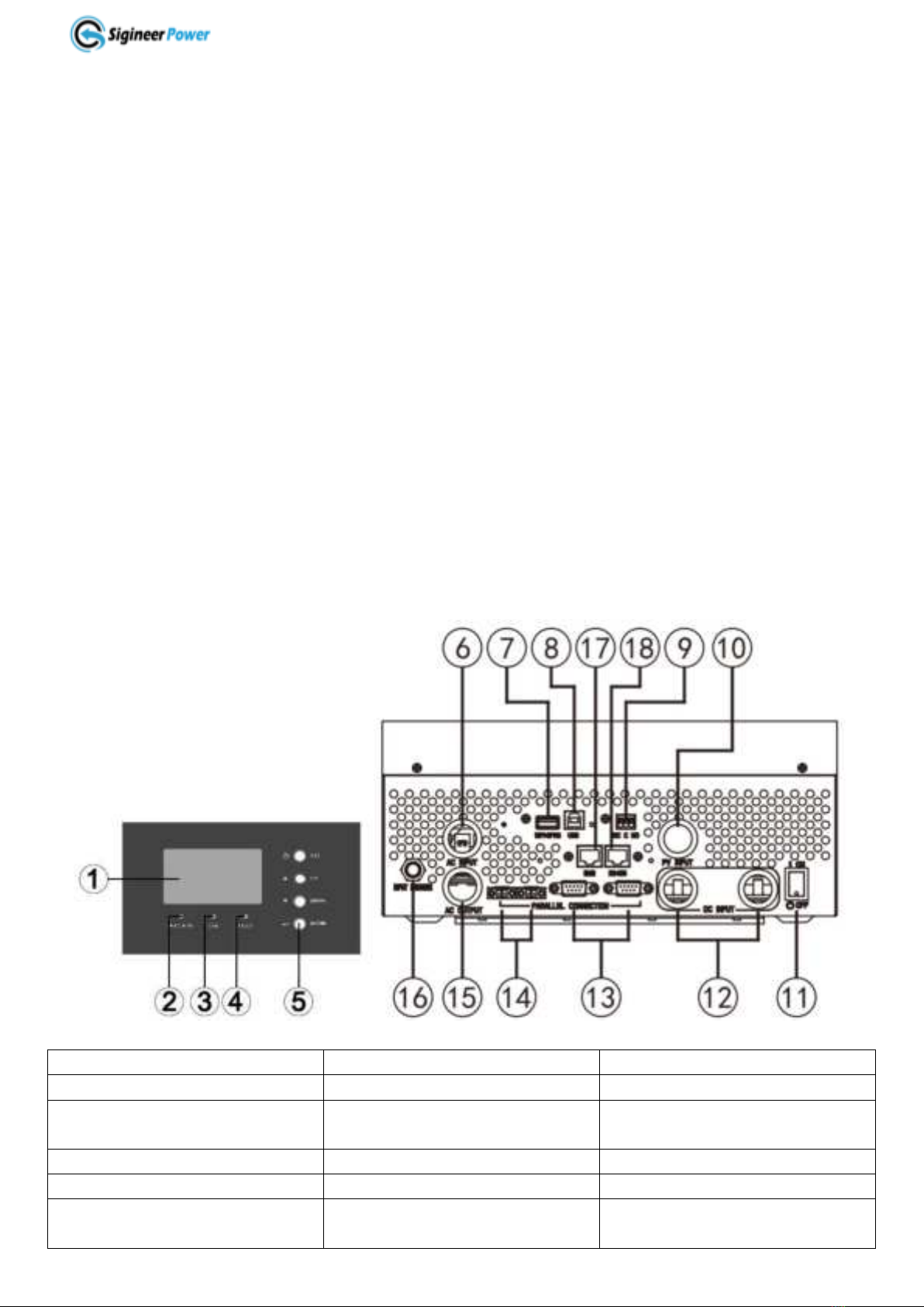
2.2 Mechanical Design
1.LCD Display
2.Status Indicator
3.Charging Indicator
4.Fault Indicator
5. Function Buttons
6. AC Input Terminal
7. Wi-Fi/GPRS Port
8. USB Port(connects to
computer)
9. Dry Contact
10. PV Input Terminal
11. ON/OFF Power Switch
12. Battery Terminals
13 Parallel Communication Ports
14 Current Sharing Ports
15 AC Output Terminal
16 AC Breaker
17 BMS Communication Port(For
RS485/CAN Protocol)
18 RS485 Communication Port
(For Expansion)

www.sigineer.com
6
2.3 Features
*Automatic Solar Charging When the Inverter is Powered Off
*Auto Generator Start
*Overload Bypass
*Battery Polarity Reverse Protection
*Smart remote monitor with WIFI or GPRS Module
*Remote LCD Panel with Adjustable Parameters
*80A MPPT Solar Charger
*Maximum THD: 3% at nominal battery voltage
*Powerful 4-stage power factor corrected battery charger
*High surge output capability, 200% peak load for 5 seconds
*Low quiescent current, low power ‘Power Saver Mode’ to conserve energy
*Equalization Charging
*20ms transfer time from AC to battery for the continuous load operation
*Thermally controlled variable speed fan for more efficient cooling
*Extensive protections against various harsh situations
*Solar Priority or SBU developed for renewable energy systems
*Parallel operation up to 6 units, capable of forming 120/240V split phase or 120/208V 3 phase output
2.4 Electrical Performance
2.4.1 DC to AC Invert
Overload Capacity
The M 3KW inverter/charger has different overload capacities, making it ideal to handle demanding loads.
1 For 110%<Load<150%, Fault (Power off) after 10 seconds.
2 For 150%<Load≤200%, Fault (Power off) after the 5 seconds.
Soft Start in Inverter Mode
The inverter is engineered with a “Soft Start” feature.
When the inverter is turned on, the output voltage gradually ramps up from 0VAC to rated voltage in about
1.2 sec. This effectively reduces otherwise very high starting inrush current drawn by AC loads such as
Switched Mode Power Supplies and inductive loads. This will result in lower motor inrush current, which
means less impact on the loads and inverter.
Caution:
After the inverter is switched on, it takes a finite time for it to self diagnose and get ready to deliver full
power. Hence, the user should always switch on the load(s) after a few seconds of switching on the inverter
to avoid switching on the load before the inverter is powered on. This may prematurely trigger the overload
protection. When a load is switched on, it may require a higher initial power surge to start. If multiple loads
are being powered, they should be switched on one by one so that the inverter is not overloaded by the
higher starting surge.
2.4.2 AC & MPPT Charger

www.sigineer.com
7
The M Series pure sine wave inverter/charger is equipped with an active PFC (Power Factor Corrected)
multistage battery charger. The PFC feature is used to control the amount of power used to charge the
batteries in order to obtain a power factor as close as possible to 1.
Unlike other inverters whose max charging current decreases according to the input AC voltage, the Sigineer
Power M Series pure sine wave inverter/charger is able to output max charge current as long as input AC
voltage is in the range of 65~140VAC, and AC frequency is qualified.
The M Series pure sine wave inverter/charger has a very rapid charge current available, and the max charge
current can be adjusted from 10A to 100% in small increments on the LCD of the inverter. This will be
helpful if this powerful charger applies charging on a small capacity battery bank.
There are three main charging stages:
Bulk Charging: This is the initial stage of charging. While Bulk Charging, the charger supplies the battery
with controlled constant current. The charger will remain in Bulk charge until the Absorption charge voltage
(determined by the Battery Type selection) is achieved.
Software timer will measure the time from charger start until the battery charger reaches 0.3V below the
boost voltage, then take this time as T0 and T0×10 = T1.
Absorb Charging: This is the second charging stage and begins after the absorb voltage has been reached.
Absorb Charging provides the batteries with a constant voltage and reduces the DC charging current in order
to maintain the absorb voltage setting.
In this period, the inverter will start a T1 timer; the charger will keep the boost voltage in Boost CV mode
until the T1 timer has run out. Then drop the voltage down to the float voltage. The timer has a minimum
time of 1 hour and a maximum time of 12 hours. When charging current reduces to below 0.01C, the charger
will go to the float charge.
Float Charging: The third charging stage occurs at the end of the Absorb Charging time. While Float
charging, the charge voltage is reduced to the float charge voltage (determined by the Battery Type
selection*). In this stage, the batteries are kept fully charged and ready if needed by the inverter.
If the battery type is selected as “lithium battery”, our charger will drastically reduce the charging current to
zero once float voltage is reached.
The charging capacity will go to peak in around 3 seconds, this may probably cause a generator to drop
frequency, making inverter transfer to battery mode.
It is suggested to gradually put charging load on the generator by switching the charging switch from min to
max, together with the 15s switch delay, our inverter gives the generator enough time to spin up.
To guarantee the best performance of AC charger when the AC input is from a
generator, the standby generator should be of at least 150% higher capacity than the
inverter.
www.sigineer.com
8
Caution:
Warning! Operation with an under-rated generator or generator with unqualified
wave form may cause premature failure which is not under warranty.
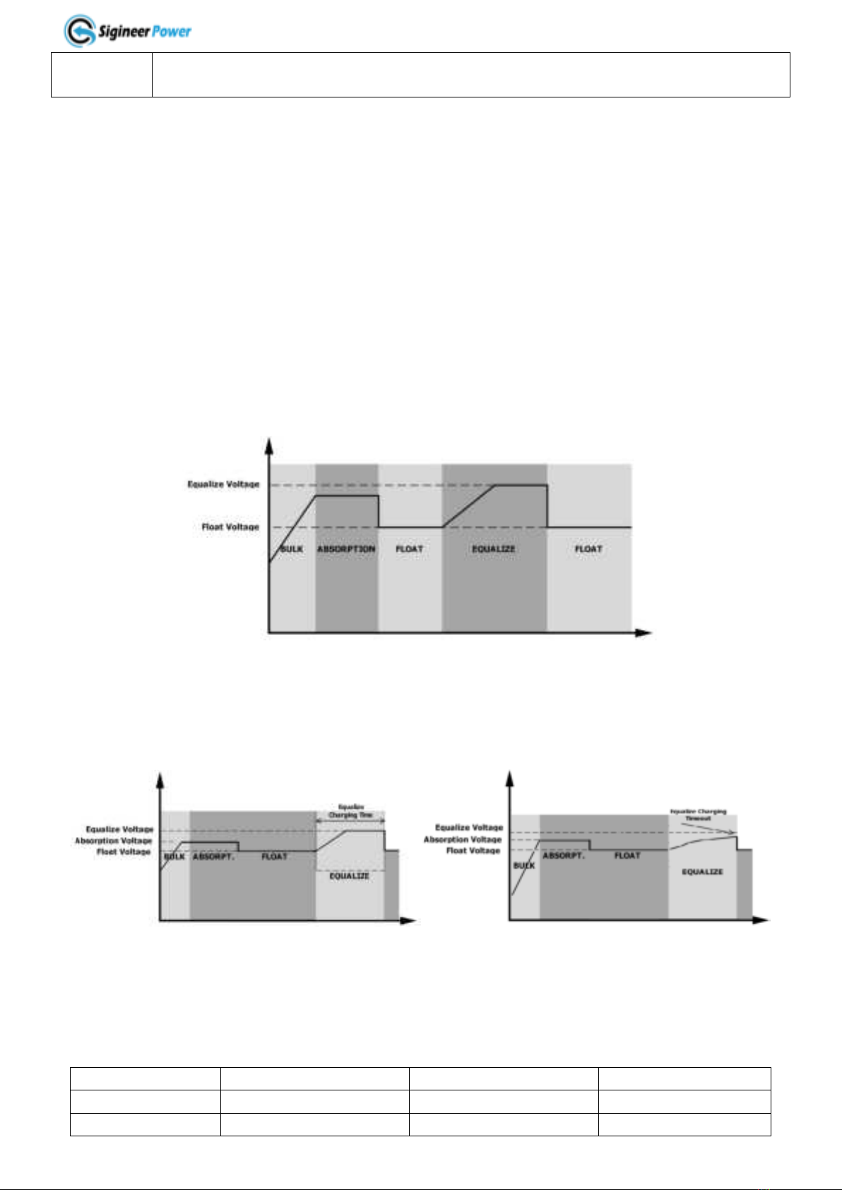
Battery Equalization
Equalization function is added into the M series inverter charge controller. It reverses the buildup of
negative chemical effects like stratification, a condition where acid concentration is greater at the bottom of
the battery than at the top. Equalization also helps to remove sulfate crystals that might have built up on the
plates. If left unchecked, this condition, called sulfation, will reduce the overall capacity of the battery.
Therefore, it’s recommended to equalize battery periodically.
How to Apply Equalization Function
You must enable battery equalization function in monitoring LCD setting program 43 first. Then, you may
apply this function in device by either one of following methods:
1. Setting equalization interval in program 47.
2. Active equalization immediately in program 48.
When to Equalize
In float stage, when the setting equalization interval (battery equalization cycle) is arrived, or equalization is
active immediately, the controller will start to enter Equalize stage.
Equalize charging time and timeout
In Equalize stage, the controller will supply power to charge battery as much as possible until battery
voltage raises to battery equalization voltage. Then, constant-voltage regulation is applied to maintain
battery voltage at the battery equalization voltage. The battery will remain in the Equalize stage until setting
battery equalized time is arrived.
However, in Equalize stage, when battery equalized time is expired and battery voltage doesn’t rise to
battery equalization voltage point, the charge controller will extend the battery equalized time until battery
voltage achieves battery equalization voltage. If battery voltage is still lower than battery equalization
voltage when battery equalized timeout setting is over, the charge controller will stop equalization and return
to float stage.
The M Series pure sine wave inverter/charger is built with MPPT solar charging modules up to 80A.
Model #
AC Charging Current
MPPT Solar Charger
Max Charging Current
M3024NC
60A
80A
140A
M3048NC
40A
80A
120A

www.sigineer.com
9
The MPPT Solar Charger will automatically work when the inverter is powered off.
Even when the power switch is in unit off position, the built-in solar charger will automatically work when
PV input voltage and battery voltage is qualified, this is to optimize solar production for battery charging.
But the inverter will not convert battery power to AC output.
When the battery is fully charged, the voltage has to drop by 2 volts (or below 95% of SOC when BMS
communication is established) to activate the charger.
2.4.3 DC&AC Transfer
While in the Standby Mode, the AC input of the inverter is continually monitored. Whenever AC power falls
out of the trip voltages, the inverter automatically transfers back to the Invert Mode with minimum
interruption to your appliances.
The transfer from AC mode to Inverter mode occurs in approximately 10 milliseconds, with the worst case
of 20 milliseconds. And it is the same time from Inverter mode to Standby mode.
Though it is not designed as a computer UPS system, this transfer time is usually fast enough to hold them
up as devices like computers can generally tolerate a max power loss of 20ms.
When the inverters are paralleled, the transfer time is <30ms.
Bypass output power derating:
When AC input voltage drops below 95Vac, the output power will be de-rated linearly to as low as 20% at
65Vac.
Output Power
Rated Power
20% Power
65V 95V
140V
Input Voltage
2.4.4 Power Saver
There are two working statuses for M3024NC and M3048NC inverters: “Power On” and “Power Off”.
When power switch is in the “Unit Off” position, the inverter is powered off.
When power switch is turned to “Power ON”, the inverter is powered on.
When the inverter is powered on, users can activate “power saver”in the program 04 of the software.
The “Power Saver”function is dedicated to conserve battery power when AC power demand is either
minimal or not required at all by the loads.
In this mode, the inverter pulses the AC output in every 30 seconds looking for an AC load (i.e., electrical
appliance). Whenever an AC load (greater than 100 watts) is turned on, the inverter recognizes the need for
power and automatically starts inverting and output goes to full voltage. When there is a small load (less
than 100 watts) detected, the inverter automatically goes back into search mode to minimize energy
consumption from the battery bank.
In “Power saver” mode, the inverter will draw power mainly in sensing moments, thus the idle consumption
is reduced from 50 watts to 30 watts.
Power Saver On
Power Saver Off
Power Saver On (Load detected)

www.sigineer.com
10
Note: The minimum power of a load to take inverter out of sleep mode (Power Saver On) is 100
Watts.
When the inverter is in idle, even there is AC input power, the inverter will discharge the battery as
the LCD, relay, fans are powered by DC.
In the “search sense”mode, the LED will blink and the inverter will make a ticking sound. At full output
voltage, the inverter will make a steady humming sound. When the inverter is used as an “uninterruptible”
power supply the search sense mode function should be defeated.
Exceptions
Some devices, when scanned by the load sensor, cannot be detected. Small fluorescent lights are the most
common example. (Try altering the plug polarity by turning the plug over.) Some computers and
sophisticated electronics have power supplies that do not present a load until line voltage is available. When
this occurs, each unit waits for the other to begin. To drive these loads, either a small companion load must
be used to bring the inverter out of its search mode, or the inverter may be programmed to remain operating
at full output voltage.
2.4.5 Protections
The M Series inverter/charger is equipped with extensive protections against various harsh situations/faults.
These protections include:
⚫AC Input over voltage protection/AC Input low voltage protection
⚫Low battery alarm/High battery alarm
⚫Over temperature protection/Overload protection
⚫Short Circuit protection (1s after fault)
⚫Battery Polarity Reverse Protection
Users can customize whether the inverter should automatically restart or not after some of these protections.
Warning !
The below mistakes will damage the inverter permanently and must be avoided:
*Reverse the PV input polarity.
*Use any third-party accessories, communication cables on the inverter.
*Wire the AC input power to the AC output terminals.
2.4.6 Remote Monitoring
The M series inverter (produced after 2021 May with P/N: DV06.CR07602) can be remotely monitored and
controlled.
It supports 4 different types of remote monitoring

www.sigineer.com
11
1. Plug in the remote LCD panel to the RS485 port.
2. Connects it to a computer via the USB port and monitor the inverter on the software.
3. Plugs a Wi-Fi or GPRS module into Wi-Fi port, monitor it on a computer or cellphone APP.
4. Connect to the RS485 port, it allows customer to monitor on their own software programmed with the
same protocol.
To monitor the inverter on a computer, please download the software (SG Solar Power Monitor) from our
website in the Support>Software Download section.
If an extra LCD switch panel is connected to the inverter via “RS485” port, together with the power switch
on the inverter top cover, the two panels will be connected and operated in parallel.
Whichever first switches from “Off” to “On”or “Power Saver On”, it will power the inverter on.
Only when both panels are turned to “Unit Off” position, will the inverter be powered off.
Note: The “Inverter On”position on the remote LCD panel doesn’t work. To power on the inverter,
the remote panel must be turned to “Power Saver On”position.
⚫The suggested length between the LCD switch panel and inverter is 20 meters.
⚫The LCD panel allows users to customize the inverter specifications on it.
Warning:
Our cables are designed with special pinouts on the connectors, so don’t use other cables, or the
remote LCD panel will not be powered on.
Never cut the remote panel cable when the cable is attached to inverter and battery is connected to the
inverter. Even the inverter is turned off, this will damage the remote PCB inside if the cable is short
circuited during cutting.
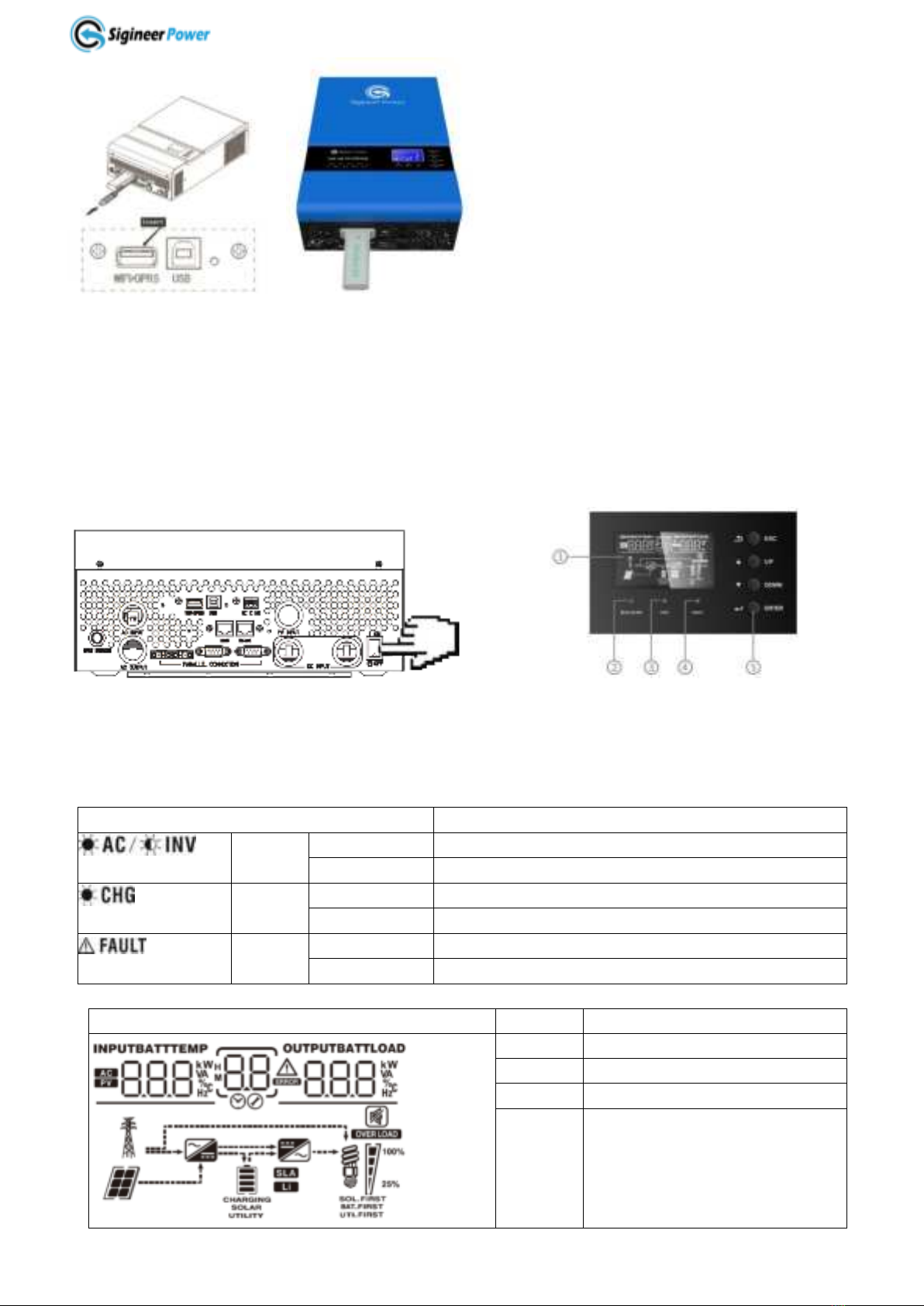
The M series inverters can be remotely monitored by a Wi-Fi or GPRS module plugged into its USB port.
The Wi-Fi / GPRS module is a plug-and-play monitoring device which allows users to monitor the status of
the PV system from a mobile phone APP or from the website anytime anywhere.
The inverter’s AC output power can be powered on and off via APP.
www.sigineer.com
12
The PV Butler APP will automatically refresh the data in every 5 minutes. To access real date, please roll
down the screen to refresh.
To monitor the inverter via both WIFI and USB port, the CUBEWiFi module can be connected via a short
extension cable.
2.4.7 LCD & Specification Setup
Press the On/Off switch to turn on the unit.
The operation and display panel area includes three LED indicators, four function keys and an LCD display.
It shows very rich operating info.
1 LCD display 2 Status Indicator 3 Charging indicator 4 Fault Indicator 5 Function buttons
LED Indicator
Operation Status
Green
Solid On
Output is powered by utility in AC mode.
Flashing
Output is powered by battery or PV in battery mode.
Green
Solid On
Battery is fully charged.
Flashing
Battery is being charged.
Red
Solid On
Fault occurs.
Flashing
Warning condition occurs.
Button
Description
ESC
Exit setting mode
UP
Go to previous selection
DOWN
Go to next selection
ENTER
Enter setting mode or confirm the
selection in setting mode.

www.sigineer.com
13
CC&CV Charge Mode
Battery Voltage @
Load >50%
Battery Voltage @50%>
Load > 20%
Battery Voltage @
Load < 20%
Icon
<48V
< 41.2V
< 43.6V
<44.8V
48-50V
41.2-43.2V
43.6-45.6V
44.8-46.8V
50-52V
43.2-45.2V
45.6-47.6V
46.8-48.8V
>52V
> 45.2V
> 47.6V
>48.8V
For model# M3024NC, the value is half of above value.
Load Information
Indicates overload.
Indicates the load level by 0-24%, 25-49%, 50-74% and 75-100%.
Icon
Function Description
Input Information
Indicates the AC input.
Indicates the PV input
Indicate input AC voltage, input frequency, PV voltage, battery voltage and
charger current.
Configuration Program and Fault Information
Indicates the setting programs.
Indicates the warning and fault conditions.
Warning Code: Flashing. Error Code: Constantly On.
Output Information
Indicate output voltage, output frequency, load percent, load in VA, load in
Watt and discharging current.
Battery Information
Indicates battery level by 0-24%, 25-49%, 50-74% and 75-100% in battery
mode and charging status in line mode.
These two signs indicate the charge priority. SOLAR indicates solar first.
UTILITY indicate utility first. SOLAR blinking indicates solar only; SOLAR
and UTILITY both on indicates combined charging.

www.sigineer.com
14
0%~24%
25%~49%
50%~74%
75%~100%
Mode Operation Information
Indicates AC input is available.
Indicates PV Input is available.
Indicates load is supplied by AC power.
Indicates the AC to DC charging.
Indicates the DC to AC conversion.
These three signs indicate the AC output priority. SOL.FIRST indicates solar
Priority. BAT.FIRST indicates battery priority. UTI.FIRST indicates utility
priority.
Mute Operation
Indicates unit audible alarm is disabled.
LCD SETTING
The M 3KW inverter LCD allows users to virtually change all its specs. It will enter setting mode if the
ENTER button is held for over 3 seconds. Press “UP” or “DOWN” button to select setting programs, and
then press “ENTER” button to confirm the selection or ESC button to exit.
Program 01: Power Priority for AC Loads
01 UEI: Utility Priority (Default)
In this mode, the utility will provide power to the AC loads as the first power source.
Solar and battery energy will provide power to the loads only when utility power is not available.
This mode works for applications with cheap utility power or using battery in power outages.
01 SOL: Solar Priority
In this mode, the solar energy provides power to the loads as the first power source.
If solar energy is insufficient, battery energy will be consumed.
Utility power will engage when one of below conditions happens:
1 Solar energy is not available (No PV production).
2 Battery voltage drops to either low-level warning voltage or the setting point in program 12 (DC to AC
Transfer Voltage in “SOL Priority”).
Once the solar power is lost, the utility will have higher priority than battery. This mode can be regarded as
“SUB”(Solar>Utility>Battery).
In this mode, the inverter will transfer between DC and AC as per the settings of program 12 and 13. Users
can set it to utility priority to stop the cycling.

www.sigineer.com
15
01 SbU: SBU Priority
As indicated by the abbreviation, the power priority comes as solar>battery>utility.
Solar energy provides power as first priority.
If solar energy is insufficient, battery energy will be consumed.
Utility provides power to the loads only when battery voltage drops to either low-level warning voltage or
the setting point in program 12(DC to AC Transfer Voltage in “SBU Priority”).
When solar is gone in SBU mode, the power priority becomes battery>utility, battery priority is higher than
utility priority.
In this mode, the inverter will transfer between DC and AC as per the settings of program 12 and 13. Users
can set it to utility priority to stop the cycling.
Note: When the inverter power priority mode is changed between the three different modes, the
setting of other programs will be saved with the associated power priority mode.
Program 02: Maximum Charging Current
24V model: default 60A, 10A~140A Settable
48V model: default 60A, 10A~120A Settable
(If Li is selected in program 5, this program can’t be set up)
The MPPT charger will stop when charging is completed. To activate the charger, the battery voltage must
drop at least 2 voltages below the lower value in program 19 and 20.
Program 03: AC Input Voltage Range
03 APL: Appliance Mode
In Appliance Mode, the acceptable AC input voltage range is 65~140VAC±5V.
03:UPS
In UPS Mode, the acceptable AC input voltage range: 95~140VAC±5V.
03: GEN
In Generator Mode, the acceptable AC input voltage range: 65~140VAC±5V. In this mode, the max
charging current is 30A.
Note: When the inverter is connected to a generator, the generator should be no less than 10KVA (no less
than 20KVA for three phase parallel system), and the inverters should be no more than 2 units in one phase.
Program 04: Power Saving Mode Enable/Disable
04: SdS
When the power saver mode is disabled, the inverter will output full voltage, and the idle power is about 50
watts.
04: SEN
If the power saver mode is enabled, the output of inverter will be off when connected load is low or not
detected.
The threshold for load detection is 100W. The idle power in power saver mode is about 30 watts.
Program 05: Battery Type
05: AGN

www.sigineer.com
16
AGM Battery (Default) : CV :56.4V, Float 54V(M3048NC). CV :28.2V, Float 27V(M3024NC).
05: FLd
Flood Battery: CV :58.4V, Float 56V(M3048NC)/ CV :19.2V, Float 28V(M3024NC).
05: USE
User-Defined
If “User-Defined” is selected, battery charge voltage and low DC cut-off voltage can be set up in program
19, 20 and 21. This setting works for GEL batteries etc.
05: US2
User-Defined 2
This US2 setting is designed for the inverter to work with lithium battery without communication via BMS.
As floating charging is not required for lithium batteries, in US2 mode, the program 19&20 will be
interlocked and set to the same value whenever one of them is changed.
Compared with USE, the charger in US2 will immediately reduce charging current when the preset voltage
in 19 is reached.
NOTE: The US2 will not optimally charge the lithium battery due to the lack of BMS communication. The
battery capacity icon bar doesn’t reflect the actual battery capacity; it is converted from battery voltage. For
more details, please refer to page 13.
When the inverter is in US2, it could not correctly display the accurate SOC of the lithium batteries.
The displayed SOC is converted from battery voltage. The SOC will change only when the battery voltage
changes big enough.
Due to the ripple current from the utility charger, when “US2” is set for charging lithium batteries, it is
recommended to set the max utility charging current at 30% of the nominal charge current.
05: LI
Lithium
This setting only works when inverter communicates with lithium battery BMS built with the same protocol.
The program is set to “LI”, the LCD will show a hidden program of 36 about BMS protocol types.
There are many lithium battery BMS communication protocols, L01, L02 to L99.
For Sigineer Power LFP power walls, the protocol is L01.
When the battery type set as “LI”, the maximum charge current can be modified by the user.
Note: When the communication fails, the inverter will cut off output.
RS485 communication protocol is L01 to L50.
The CAN communication protocol is L51 to L99.
Program 06: Automatic Overload Restart
06: LFd
Disabled.
06: LFE
When this feature is enabled, the inverter will attempt to restart 3 times after overloads, if it still fails to start
the load after 3 attempts, it will show warning code 07.
Program 07: Automatic OverTemp Restart
Program 08: AC Output Voltage

www.sigineer.com
17
The AC output voltage between hot and neutral can be set to 100V, 110V and 120V(default).
Program 09: AC Output Frequency
The AC Output Frequency can be set to 50Hz or 60Hz(default).
Program 10: Number of 12V Batteries Connected in Series
The default value is 4 for model # M3048NC, and 2 for model # M3024NC. This program is only a
reminder about the 12V battery quantity.
Program 11: Maximum Utility Charging Current
Model #
Default Value
Resettable Range
M3024NC
30A
0-60A
M3048NC
30A
0-40A
The solar charger always has higher priority than the utility charger.
If the max charging current (Program 02) and utility charger (Program 11) is set to the same value, the solar
charger will still work before utility charger engages.
If setting value in Program 02 is smaller than that in Program 11, the final charging current is set according
to Program 02 for utility charger.
Program 12 DC to AC Transfer Voltage
The setting works when program 01 is in “SBU Priority” or “Solar Priority” Mode.
Model #
Default Value
Resettable Range
M3024NC
23V/50%
22V~25.6V/6%-95%
M3048NC
46V/50%
44V~51.2V/6%-95%
The battery SOC will be displayed when BMS communication is established.
Program 13 AC to DC Transfer Voltage
The setting works when program 01 is in “SBU Priority” or “Solar Priority” Mode.
Model #
Default Value
Resettable Range
M3024NC
27V/95%
24V~29V/10%-100%
M3048NC
54V/95%
48V~58V/10%-100%
The battery SOC will be displayed when BMS communication is established.
Program 14 Charge Power Source Priority
14:CSO
Solar Priority (Default)
Solar energy will charge battery as first priority.
Utility will charge battery only when solar energy is not available (lost).
14:CUT
Utility Priority
Utility will charge battery as first priority.
Solar energy will charge battery only when utility power is not available (lost).
14:SNU
Solar and Utility

www.sigineer.com
18
Solar energy and utility will both charge battery.
14:OSO
Solar Only
Solar energy will be the only charger source no matter utility is available or not.
But when the battery voltage drops below the setting of 21(Low DC Cut-off Voltage), the utility power will
be used to force a charging cycle to avoid battery over discharging.
If this off grid solar inverter is working in DC to AC invert mode, only solar energy can charge the battery.
Solar energy will charge battery if it's available and sufficient.
Program 15 Alarm On/Off Control
Program 16 Backlight On/Off Control
When off is set, the LCD will go dim after 60 seconds left unattended.
Program 17 Beeps once between AC and DC Transfer
Program 18 Overload Bypass
When enabled, the unit will transfer to line mode if overload occurs in battery mode.
Program 19 Constant Voltage Charging Voltage
Model #
Default Value
Resettable Range
M3024NC
28.2V
24V~28.2V
M3048NC
56.4V
48V~58.4V
If user-defined setting (USE/US2) is selected in program 5, this program can be set up.
Program 20 Float Charging Voltage
Model #
Default Value
Resettable Range
M3024NC
27V
24.0V~28.2V
M3048NC
54V
48V~58.4V
If user-defined setting (USE/US2) is selected in program 5, this program can be set up
Program 21 Low DC Cut-Off Voltage
Model #
Default Value
Resettable Range
M3024NC
21V/20%
20V~24V/5%-50%
M3048NC
42V/20%
40V~48V/5%-50%
The battery SOC will be displayed when BMS communication is established.
After User-defined (USE/US2) setting is selected in program 5, this program can be set up
Low DC cut-off voltage will be fixed to setting value regardless of load percentage.
When low DC Cut-Off voltage is reached:
1. If battery is the only power source, inverter will shut down.
2. If PV energy and battery power are available, inverter will charge battery without AC output.
3. If PV energy, battery power and utility are all available, inverter will transfer to line mode and provide
output power to loads and charge the battery at the same time.

www.sigineer.com
19
When low battery voltage protection occurs and qualified PV or AC power inputs, the inverter will
automatically charge and invert DC to AC when the battery voltage reach 54V for M3048NC or 27V for
M3024NC (Or 10% more SOC than low battery cut off in Lithium mode).
To make it work, the power switch must remain in the original “ON”position.
The minimal voltage for the LCD to illuminate is 30Vdc for M3048NC, and 15V for M3024NC.
Program 22 Solar Power Balance
When enabled, the solar input power will be automatically adjusted according to the load wattage.
Max solar input power = Max battery charging power +Connected load power.
If disabled, the solar input power will be the same to the max battery charging power no matter how much
loads are connected. The max battery charging power will be based on the setting current in program 2.
(Max. solar power = Max. battery charging power)
Program 23 AC Output Mode
This setting is only available when the inverter is in standby mode (Switch off).
Power saving function will be automatically disabled when in parallel operation.
23:SIG
Single Unit Operation.
When unit operates separately and is not in parallel operation.
23:PAL
Parallel in Single Phase
When the units are used in parallel with single phase
23: 3P1/3P2/3P3
Three Phase: 3P1, 3P2, 3P2
It requires at least 3 inverters to support three-phase equipment, 1 inverter in each phase.
Please select “3P1” for the inverters connected to L1 phase, “3P2” for the inverters connected to L2 phase
and “3P3” for the inverters connected to L3 phase.
Do NOT connect share current cable between units on different phases.
23:2P0/2P1/2P2
Split Phase: 2P0, 2P1, 2P2
Select “2P0” for the inverters connected to L1 phase;
If connect split phase 120V/208V, select “2P1” for inverters connected to L2 phase;
If connect split phase 120V/240V, select “2P2” for inverters connected to L2 phase
Do NOT connect share current cable between units on different phases.
Program 28 Address setting
Default 001. 001-255. Settable. It is for external solar charger expansion.
Program 36 Lithium BMS Protocol
For Sigineer Power LFP power walls, the protocol is L01.
Please refer to “05: LI”for details.
Program 43 Battery Equalization

www.sigineer.com
20
If “Flooded” or “User-Defined” is selected in program 05, this program can be set up. The Equalization is
banned for AGM batteries.
Program 44 Battery Equalization Voltage
Model #
Default Value
Resettable Range
M3024NC
29.2V
24V~29.2V
M3048NC
58.4V
48-58.4V
Program 45 Battery Equalized Time
Default 60min, 5min~900min Settable
Program 46 Battery Equalized Timeout
Default 120min, 5min~900min Settable
Program 47 Equalization Interval
Default 30days, 1 day~90 days Settable
Program 48 Equalization Activated Immediately
If equalization function is enabled in program 23, this program can be set up. If “Enable” is selected in this
program, it’s to activate battery equalization immediately and LCD main page will shows “Eq”.If “Disable”
is selected, it will cancel equalization function until next activated equalization time arrives based on
program 27 setting. At this time, “Eq” will not be shown in LCD main page
Program #
Description
ICON
01 Power Priority for AC
Loads
Utility Priority
01 Power Priority for AC
Loads
Solar Priority
01 Power Priority for AC
Loads
SBU Priority
02 Maximum Charging
Current
Max PV+Utility Charging Current
03 AC Input Voltage Range
Appliance Mode (Default)
03 AC Input Voltage Range
UPS Mode
03 AC Input Voltage Range
Generator mode
04: Power Saving Mode
Saving mode disable (Default)
04: Power Saving Mode
Saving mode enable
05 Battery Type
AGM Battery (Default)
05 Battery Type
Flood Battery
05 Battery Type
User-Defined
This manual suits for next models
1
Table of contents
Other Sigineer Power Batteries Charger manuals


