Sigineer Power PSW71512NC User manual

www.sigineer.com
1
Sigineer Power
Pure Sine Wave Inverter/Charger
User’s Manual(1.5KW to 6KW)
Version 6.0 (PN:50000-20221216)
Sigineer Power Limited
Email: info@sigineer.com
TEL: +86 769 82817616
WhatsApp / iMessage / Wechat :+86 189 9808 0464
US Warehouse: 205 E Alma Ave A6, San Jose, CA 95112
Add: Bld A, Jiali Industrial Zone, Yuanfen Rd, Longhua, Shenzhen, 518100, China
Manufacturer Information

www.sigineer.com
2
Table of Contents
1 Important Safety Information.................................................................................................................................................3
1.1 General Safety Precautions..................................................................................................................................................3
1.2 Precautions When Working with Batteries..........................................................................................................................3
2 Introduction............................................................................................................................................................................ 4
2.1 General Information ............................................................................................................................................................4
2.2 Application ..........................................................................................................................................................................5
2.3 Mechanical Drawing ..........................................................................................................................................................5
2.4 Features ..............................................................................................................................................................................7
2.5 Electrical Performance ......................................................................................................................................................8
2.5.1 Invert ........................................................................................................................................................................8
2.5.2AC Charger...............................................................................................................................................................8
2.5.3 Transfer................................................................................................................................................................... 12
2.5.4 Power Saver............................................................................................................................................................12
2.5.5 Protections..............................................................................................................................................................13
2.5.6 LED Indicator......................................................................................................................................................... 14
2.5.7 LCD Remote Control.............................................................................................................................................. 14
2.5.8AudibleAlarm ........................................................................................................................................................15
2.5.9 FAN Operation .......................................................................................................................................................16
2.5.10 DIP Switches ........................................................................................................................................................ 16
2.5.11Auto Generator Start.............................................................................................................................................18
2.5.12 Battery Temperature Sensing................................................................................................................................ 19
2.5.13 GFCI Outlet..........................................................................................................................................................19
2.5.14Automatic Neutral-to-Ground Bonding................................................................................................................20
2.5.15 Lithium Battery Wakeup....................................................................................................................................... 21
2.5.16 Other Features ...................................................................................................................................................... 22
3 Installation............................................................................................................................................................................22
3.1 Location.....................................................................................................................................................................22
3.2 DC Wiring Recommendation ....................................................................................................................................22
3.3 AC Wiring Recommendation.....................................................................................................................................24
3.4 Grounding.................................................................................................................................................................. 26
3.5 Mounting Flange ....................................................................................................................................................... 27
4 Maintenance & Troubleshooting.......................................................................................................................................... 29
5 Warranty...............................................................................................................................................................................31
Appendix 1 : Sigineer Power 1500W Inverter/Charger Spec Sheet........................................................................................32
Appendix 2 : Sigineer Power 2000W-6000W Inverter/Charger Spec Sheet...........................................................................34
Appendix 3: Circuitry Scheme................................................................................................................................................36
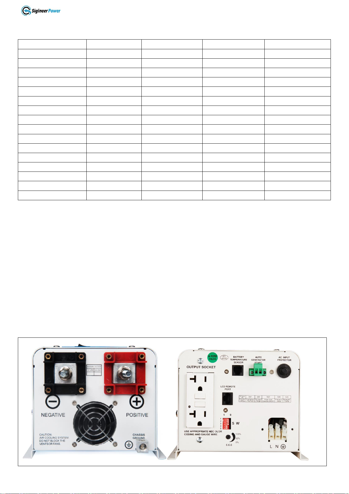
Please record the Sigineer Power unit’s model and serial number in case you need to provide this
information in the future. It is much easier to record this information now than try to gather it after
the unit has been installed.
Model Number:
Serial Number:

www.sigineer.com
3
1 Important Safety Information
Save This Manual! Read this manual before installation, it contains important safety, installation
and operating instructions. Keep it in a safe place for future reference.
All wiring must follow the National Electric Code, Provincial or other codes in effect at the time
of installation, regardless of suggestions in this manual. All wires should be copper conductors.
1.1 General Safety Precautions
1.1.1 Before installing and using the Sigineer Power Pure Sine Wave Inverter/Charger, read the manual and
cautionary markings on the Inverter/Charger enclosure. Be sure to read all instructions and cautionary
markings for any equipment attached to this unit. Installers must be certified technicians or electricians.
1.1.2 This product is designed for indoor/compartment installation. Do not expose the inverter/charger to
rain, snow, spray, bilge or dust. To reduce the risk of hazard, do not cover or obstruct the ventilation
openings. Do not install the inverter/charger in a zero-clearance compartment. Overheating may result.
Allow at least 30CM (11.81 inches) of clearance around the inverter for air flow. Make sure that the air can
circulate freely around the unit. A minimum air flow of 145CFM is required.
1.1.3 To avoid a risk of fire and electronic shock. Make sure that existing wiring is in good electrical
condition; and that wire size is not undersized. Do not operate the Inverter with damaged or substandard
wiring.
1.1.4 This equipment contains components which can produce arcs or sparks. To prevent fire or explosion
do not install in compartments containing batteries or flammable materials or in locations which require
ignition protected equipment. This includes any space containing gasoline-powered machinery, fuel tanks,
or joints, fittings, or other connection between components of the fuel system. See Warranty for instructions
on obtaining service.
1.1.5 Do not dis-assemble the Inverter/Charger. It contains no user serviceable parts. Attempting to service
the Inverter/Charger yourself may result in a risk of electrical shock or fire. Internal capacitors remain
charged after all power is disconnected.
1.1.6 To reduce the risk of electrical shock, disconnect both AC and DC power from the Inverter/Charger
before attempting any maintenance or cleaning. Turning off controls will not reduce this risk
CAUTION: Equipment damage
The output side of the inverter’s AC wiring should at no time be connected to public power or a generator.
This condition is far worse than a short circuit. If the unit survives this condition, it will shut down until
corrections are made.
Installation should ensure that the inverter’s AC output is, at no time, connected to its AC input.
WARNING:LIMITATIONS ON USE
SPECIFICALLY, PLEASE NOTE THAT THE INVERTER/CHARGER SHOULD NOT BE USED IN
CONNECTION WITH LIFE SUPPORT SYSTEMS OR OTHER MEDICAL EQUIPMENT OR DEVICES.
WE MAKE NO WARRANTY OR REPRESENTATION IN CONNECTION WITH THEIR PRODUCTS
FOR SUCH USES. USING THE INVERTER/CHARGER WITH THESE PARTICULAR EQUIPMENTS
IS AT YOUR OWN RISK.
1.2 Precautions When Working with Batteries
1.2.1 If battery acid contacts skin or clothing, wash immediately with soap and water. If acid enters eye,
immediately flood eye with running cold water for at least 20 minutes and get medical attention
immediately.

www.sigineer.com
4
1.2.2 Never smoke or allow a spark or flame in the vicinity of battery or engine.
1.2.3 Do not drop a metal tool on the battery. The resulting spark or short-circuit on the battery of other
electrical part may cause an explosion.
1.2.4. Remove personal metal items such as rings, bracelets, necklaces, and watches when working with a
lead-acid battery. A lead-acid battery produces a short-circuit current high enough to weld a ring or the like
to metal, causing a severe burn.
1.2.5 To reduce the risk of injury, charge only rechargeable batteries such as deep-cycle lead acid, lead
antimony, lead calcium gel cell, absorbed mat, NiCad/NiFe or Lithium battery. Other types of batteries may
burst, causing personal injury and damage.
1.2.6 Don’t install the inverter near batteries, the inverter may heat battery electrolyte and cause corrosive
fumes to vent and damage/corrode nearby electronics or metals.
2 Introduction
2.1 General Information
Thank you for purchasing the Sigineer Power Pure Sine Wave Inverter/Charger.
The Sigineer Power Pure Sine Wave Inverter/Charger is a transformer based inverter and battery charger
with an unprecedented conversion efficiency of 90%.
Packed with unique features, it is one of the most technically advanced inverter/charger on the market.
It features power factor corrected, sophisticated multi-stage charging control and pure sine wave output with
high surge capability to meet the power needs of all sorts of demanding loads without putting the equipment
at risk.
The transformers of the whole line have been consistently improved for years to achieve the best balance of
conversion efficiency, idle consumption, and maximum THD.
The idle consumption of the Sigineer Power inverter/charger is ultra low, roughly 1.5% of its rated power.
Loaded with full linear loads, the maximum THD of the Sigineer Power is 3% at nominal battery voltage
and 10% at low battery voltage alarm point.
These special features make this line compete very well with its high frequency counterparts.
The powerful battery charger of Sigineer Power Inverter/Charger comes with Battery Temperature Sensing
for increased charging precision.
The generous 300% surge capacity of 20 seconds makes it possible to support demanding inductive loads.
The Sigineer Power models are available in 120Vac(single phase) and 120/240Vac(split phase), together
with a manual 50Hz/60Hz frequency switch, the product line is compatible with all the major utility
standards worldwide.
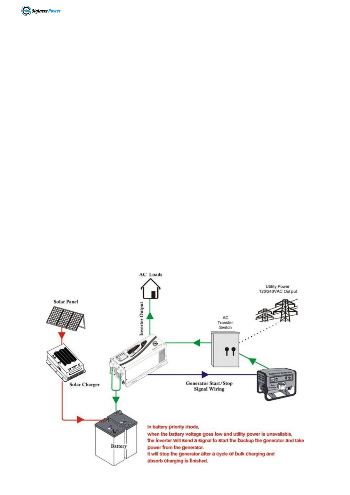
The AC/Battery priority, auto generator start functionality make it ideally suitable to work in either backup
power or renewable energy applications.
When customized to Battery priority mode via a DIP switch, the inverter will extract maximum power from
external power sources in renewable energy systems and a minimal cycle of battery will be required. With
the availability of auto generator start, an electrical generator can be integrated into the system and started
when the battery voltage goes low.
With an audible buzzer and an LCD display, the inverter gives the users comprehensive information of the
operation status, making it easier for maintenance and troubleshooting.
Thus the Sigineer Power Pure Sine Wave Inverter/Charger is suitable for a myriad of applications including
renewable energy systems, utility, truck, RV and emergency vehicles etc.
To get the most out of the power inverter, it must be installed, used and maintained properly. Please read the
www.sigineer.com
5
instructions in this manual before installation and operation.
Model #
Nominal Power
DC Input
AC Input
AC Output
PSW71512NC
1500W
12Vdc
120Vac
120Vac
PSW71524NC
1500W
24Vdc
120Vac
120Vac
APC3012NC
3000W
12Vdc
120Vac
120Vac
APC3012D
3000W
12Vdc
240Vac
120/240Vac
APC3024NC
3000W
24Vdc
120Vac
120Vac
APC3024D
3000W
24Vdc
240Vac
120/240Vac
APC3048NC
3000W
48Vdc
120Vac
120Vac
APC3048D
3000W
48Vdc
240Vac
120/240Vac
APC4012NC
4000W
12Vdc
120Vac
120Vac
APC4012D
4000W
12Vdc
240Vac
120/240Vac
APC4024NC
4000W
24Vdc
120Vac
120Vac
APC4024D
4000W
24Vdc
240Vac
120/240Vac
APC4048NC
4000W
48Vdc
120Vac
120Vac
APC4048D
4000W
48Vdc
240Vac
120/240Vac
APC6024D
6000W
24Vdc
240Vac
120/240Vac
APC6048D
6000W
48Vdc
240Vac
120/240Vac
2.2 Application
Power tools–circular saws, drills, grinders, sanders, buffers, weed and hedge trimmers, air compressors.
Office equipment –computers, printers, monitors, facsimile machines, scanners.
Household items –vacuum cleaners, fans, fluorescent and incandescent lights, shavers, sewing machines.
Kitchen appliances –coffee makers, blenders, ice markers, toasters.
Industrial equipment –metal halide lamp, high –pressure sodium lamp.
Home entertainment electronics –television, VCRs, video games, stereos, musical instruments.
2.3 Mechanical Drawing

www.sigineer.com
6
SIDE VIEW OF MODEL # : PSW71512NC / PSW71524NC
SIDE VIEW OF MODEL # :
APC3012NC /APC3024NC /APC3048NC/APC4012NC/APC4024NC/APC4048NC
www.sigineer.com
7
SIDE VIEW OF MODEL # :
APC3012D /APC3024D/APC3048D/APC4012D/APC4024D/APC4048D/APC6024D/APC6048D
2.4 Features
Auto Generator Start
Battery Temperature Sensing for increased charging precision
Lithium Battery(0Vdc) Wakeup
Automatic Neutral to Ground Bonding for 120Vac models
Maximum THD: 3% at nominal battery voltage
Maximum 90% conversion efficiency
Powerful 4-stage power factor corrected battery charger, settable from 0%-100%
High surge output capability, 300% peak load for 20 seconds
Fully isolated AC output from battery input
Ultra low quiescent current, low power ‘Power Saver Mode’ to conserve energy
Battery type selector for 8 types of batteries and de-sulphation for completely drained batteries
10 ms transfer time from AC to battery for the continuous load operation
Optional remote control with LCD display
15 sec DC to AC transfer delay, improved protection for generator driven loads
Thermally controlled variable speed fan for more efficient cooling
Extensive protections against various harsh situations

www.sigineer.com
8
2.5 Electrical Performance
2.5.1 Invert
Topology
The Sigineer Power pure sine wave inverter/charger is built according to the following topology.
Invert: Full Bridge Topology.
Charge: Isolated Boost Topology
When operating in invert mode, the direct current (DC) that enters the inverter from the batteries is filtered
by a large input capacitor and switched “On” and “Off” by the Metal Oxide Silicon Field Effect Transistors
(MOSFET) at a rate of 50 Hz or 60Hz, and directed into the transformer which steps the voltage up to 230 or
120 volts. The unit has a 16bit, 4.9MHZ microprocessor to control the output voltage and frequency as the
DC input voltage and/or output load varies.
Because of high efficiency MOSFETs and the heavy transformers, it outputs PURE SINE WAVE AC with
an average THD of 7% (min 3%, max 10% under full linear loads) depending on the load connected and
battery voltage.
The peak invert efficiency of Sigineer Power is 90%.
Overload Capacity
The Sigineer Power inverter/charger has different overload capacities, making it ideal to handle demanding
loads.
1 For 110%<Load<125%(±10%), no audible alarm in 14 minutes, beeps 0.5s every 1s in the 15th minute,
and Fault(Turn off) after the 15th minute.
2 For 125%<Load<150%(±10%), beeps 0.5s every 1s and Fault(Turn off) after the 1 minute.
3 For 300%≧Load>150%(±10%), beeps 0.5s every 1s and Fault(Turn off) after 20s.
Soft Start in Inverter Mode
The inverter is engineered with a “Soft Start” feature.
When the inverter is turned on, the output voltage gradually ramps up from 0VAC to rated voltage in about
1.2 sec. This effectively reduces otherwise very high starting inrush current drawn by AC loads such as
Switched Mode Power Supplies and inductive loads. This will result in lower motor inrush current, which
means less impact on the loads and inverter.
Caution:
After the inverter is switched on, it takes a finite time for it to self diagnose and get ready to deliver full
power. Hence, always switch on the load(s) after a few seconds of switching on the inverter. Avoid
switching on the inverter with the load already switched on. This may prematurely trigger the overload
protection. When a load is switched on, it may require an initial higher power surge to start. Hence, if
multiple loads are being powered, they should be switched on one by one so that the inverter is not
overloaded by the higher starting surge if all the loads are switched on at once.
2.5.2 AC Charger
The Sigineer Power pure sine wave inverter/charger is equipped with an active PFC (Power Factor
Corrected) multistage battery charger. The PFC feature is used to control the amount of power used to
charge the batteries in order to obtain a power factor as close as possible to 1.
Unlike other inverters whose max charging current decreases according to the input AC voltage, Sigineer
Power pure sine wave inverter/charger is able to output max charge current as long as input AC voltage is in
the range of 164-253VAC for 240Vac models (95-127VAC for 120V models), and AC frequency is in the

www.sigineer.com
9
range of 48-54Hz for 50Hz (58-64Hz for 60Hz).
The Sigineer Power pure sine wave inverter/charger has a very rapid charge current available, and the max
charge current can be adjusted from 0%-100% via a liner switch on the DC side of the inverter. This will be
helpful if this powerful charger apply charging on a small capacity battery bank.
Choosing “0”in the battery type selector will disable charging function.
There are three main charging stages:
Bulk Charging: This is the initial stage of charging. While Bulk Charging, the charger supplies the battery
with controlled constant current. The charger will remain in Bulk charge until the Absorption charge voltage
(determined by the Battery Type selection) is achieved.
Software timer will measure the time from charger start until the battery charger reaches 0.3V below the
boost voltage, then take this time as T0 and T0×10 = T1.
Absorb Charging: This is the second charging stage and begins after the absorb voltage has been reached.
Absorb Charging provides the batteries with a constant voltage and reduces the DC charging current in order
to maintain the absorb voltage setting.
In this period, the inverter will start a T1 timer; the charger will keep the boost voltage in Boost CV mode
until the T1 timer has run out. Then drop the voltage down to the float voltage. The timer has a minimum
time of 1 hour and a maximum time of 12 hours.
Float Charging: The third charging stage occurs at the end of the Absorb Charging time. While Float
charging, the charge voltage is reduced to the float charge voltage (determined by the Battery Type
selection*). In this stage, the batteries are kept fully charged and ready if needed by the inverter.
If theA/C is reconnected or the battery voltage drops below 12Vdc/24Vdc/48Vdc, the charger will reset the
cycle above.
If the charge maintains the float state for 10 days, the charger will deliberately reset the cycle to protect the
battery.

www.sigineer.com
10
Battery
Type
Selector
Description
Boost
Charge(C.V)
Float
Charge
Boost
Charge(C.V)
Float
Charge
Boost
Charge(C.V)
Float
Charge
For 12Vdc Models
For 24Vdc Models
For 48Vdc Models
0
Charger Off
1
Gel USA
14
13.7
28
27.4
56
54.8
2
AGM 1
14.1
13.4
28.2
26.8
56.4
53.6
3
AGM 2
14.6
13.7
29.2
27.4
58.4
54.8
4
Sealed lead acid
14.4
13.6
28.8
27.2
57.6
54.4
5
Gel EURO
14.4
13.8
28.8
27.6
57.6
55.2
6
Open lead acid
14.8
13.3
29.6
26.6
59.2
53.2
7
Calcium
15.1
13.6
30.2
27.2
60.4
54.4
8
De sulphation
(4 hours)
15.5
15.5
31
31
62
62
9
Lithium Battery
Customized
Customized
Customized
Customized
Customized
Customized
De-sulphation
The de-sulphation cycle on switch position 8 is marked in red because this is a very dangerous setting if you
do not know what you are doing. Before ever attempting to use this cycle you must clearly understand what
it does and when and how you would use it.
What causes sulphation? This can occur with infrequent use of the batteries, nor if the batteries have been
left discharged so low that they will not accept a charge. As the saying goes, desperate diseases must have
desperate remedies. This cycle is a very high voltage charge cycle especially designed to try to break down
the sulphated crust that is preventing the plates from taking a charge and thus allow the plates to clean up
and accept a charge once again.
Warning!
The de-sulphation charging should not be carried out on batteries with good conditions.
For Sigineer Power’s model of APC6024D and APC6048D Inverter chargers, the battery type selector
position of “9”is customized with special charging algorithm for lithium battery modules from Tesla Model
S.
The algorithm has only Bulk Charging (Constant Current) to charge the battery, when the battery is charged
to high voltage alarm, the charger will shut off and inverter goes to battery mode.
Model #
APC6024D
APC6048D
Low Battery Cut Off
18V
36V
Low Battery Voltage Alarm/ Charger Activation
23.5V
47V
High Battery Voltage Alarm/ Charger Cut Off
25.25V
50.5V
High Battery Cut Off
25.5V
51V

www.sigineer.com
11
Warning: The output of these units will be de-rated by about 10% when the battery voltage drops below the
nominal cut off of 20V and 40V.
For other models, the battery type selector position of “9”is customized with special charging algorithm for
Sigineer Power lithium battery packs
Model #
PSW71512NC
APC3012NC
APC3012D
APC4012NC
APC4012D
PSW71524NC
APC3024NC
APC3024D
APC4024NC
APC4024D
APC3048NC
APC3048D
APC4048NC
APC4048D
Constant Voltage Charge
13.6V
27.2V
54.4V
Floating Charging
N/A
N/A
N/A
Low Battery Alarm
12V/12.5V
24V/25V
48V/50V
Low Battery Cutoff
11.5V/12V
23V/24V
46V/48V
Note: The battery type selector of “0”will disable the charger when the battery voltage is over 11.25Vdc for
12V models, 22.5V for 24V models, 45V for 48V models.
Charging depleted batteries
Unlike some other competing inverters that need a qualified DC voltage to activate its charger, the Sigineer
Power pure sine wave inverter/charger allows start up and power bypass with depleted batteries.
As long as qualified AC power inputs, these inverters will charge batteries even when the battery voltage is
0 volt. This is a great feature to wake up lithium battereis.
Charging current for each model
Model #
Battery
Voltage
Charging
Current
Model #
Battery
Voltage
Charging
Current
PSW71512NC
12 Vdc
45±5 Amp
PSW71524NC
24 Vdc
25±5 Amp
APC3012NC
APC3012D
12 Vdc
80±5 Amp
APC4012NC
APC4012D
12 Vdc
100±5 Amp
APC3024NC
APC3024D
24 Vdc
45±5 Amp
APC4024NC
APC4024D
24 Vdc
55±5 Amp
APC3048NC
APC3048D
48 Vdc
25±5 Amp
APC4048NC
APC4048D
48 Vdc
35±5 Amp
APC5024D
24 Vdc
65±5 Amp
APC6024D
24 Vdc
80±5 Amp
APC5048D
48 Vdc
40±5 Amp
APC6048D
48 Vdc
50±5 Amp
The charging capacity will go to peak in around 3 seconds, this may probably cause a generator to drop
frequency, making inverter transfer to battery mode.
It is suggested to gradually put charging load on the generator by switching the charging switch from min to
max, together with the 15s switch delay, our inverter gives the generator enough time to spin up.
Changing max charging current
The battery type selector position of "0" will disable battery charger when battery voltage is over 11.25Vdc
for 12Vdc models, 22.5V for 24V models, 45V for 48V model.
If the battery voltage is below this level, the inverter will force the charging when AC input is qualified.

www.sigineer.com
12
The "Charge Current Control" knob will enable the user to control the max charging current from 15% to
maximum.
Caution
Please use a small jeweler’s style flat-head screwdriver to turn the charge current
control switch gently to avoid breakage due to over-turning.
To guarantee the best performance ofAC charger when the AC input is from a
generator, the standby generator should be of at least 150% higher capacity than the
inverter.
Warning! Operation with an under-rated generator or generator with unqualified
wave form may cause premature failure which is not under warranty.
2.5.3 Transfer
While in the Standby Mode, theAC input of the inverter is continually monitored. WheneverAC power falls
out of the trip voltages, the inverter automatically transfers back to the Invert Mode with minimum
interruption to your appliances.
The transfer from Standby mode to Inverter mode occurs in approximately 6 milliseconds, with the worst
case of 10 milliseconds. And it is the same time from Inverter mode to Standby mode.
Though it is not designed as a computer UPS system, this transfer time is usually fast enough to hold them
up as devices like computers can generally tolerate a max power loss of 20ms.
There is a 15-second delay from the time the inverter senses that continuously qualified AC is present at the
input terminals to when the transfer is made. This delay is built in to provide time for a generator to spin-up
to a stable voltage and avoid relay chattering. The inverter will not transfer to generator until it has locked
onto the generator’s output. This delay is also designed to avoid frequent switch when input utility is
unstable.
2.5.4 Power Saver
There are two different working statuses for SIGINEER POWER inverter: “Power On”and “Power Off”.
When power switch is in “Unit Off”position, the inverter is powered off.
When power switch is turned to either “Power Saver Auto”or “Power Saver Off”, the inverter is powered
on.
Power saver function is dedicated to conserve battery power when AC power is not or little required by the
loads.
In this mode, the inverter pulses the AC output looking for an AC load (i.e., electrical appliance). Whenever
an AC load (greater than 25 watts) is turned on, the inverter recognizes the need for power and automatically
starts inverting and output goes to full voltage. When there is no load (or less than 25 watts) being detected,
the inverter will automatically goes back into search mode to minimize energy consumption from the battery
bank.
In “Power saver on”mode, the inverter will draw power mainly in sensing moments, thus the idle
consumption is significantly reduced.
The inverter is factory defaulted to detect load for 250ms in every 3 seconds. This power sensing can be
customized to “Unit off charging”via the SW3 on DIP switch.

www.sigineer.com
13
Power saver on
Power saver off
Power saver on (Load detected)
Note: The minimum power of a load to take inverter out of sleep mode (Power Saver On) is 50 Watts. For
split phase models, the power threshold of sleep mode is 50W between Hot1 and Neutral and 200W between
Hot 1 and Hot 2. There is no load detection between Hot2 and Neutral.
The whole Sigineer Power inverter line is designed with extraordinarily low idle power consumption which
is approximately 2.5% of its rated power.
Sigineer Power Inverter/Charger Idle Power Consumption(in Watts)
Model
Power Saver Off
Power Saver Auto
Idle(Max)
3Secs(Max)
Unit Off Charging
1.5KW
35W
9W
3W
2KW
59W
10.0W
3KW
75W
15.0W
4KW
110W
20.0W
5KW
130W
25.0W
6KW
150W
25.0W
When in the search sense mode, the green power LED will blink and the inverter will make a ticking sound.
At full output voltage, the green power LED will light steadily and the inverter will make a steady humming
sound. When the inverter is used as an “uninterruptible” power supply, the search sense mode function
should be deactivated.
Exceptions
Some devices when scanned by the load sensor cannot be detected. Small fluorescent lights are the most
common example. (Try altering the plug polarity by turning the plug over.) Some computers and
sophisticated electronics have power supplies that do not present a load until line voltage is available. When
this occurs, each unit waits for the other to begin. To drive these loads either a small companion load must
be used to bring the inverter out of its search mode, or the inverter may be programmed to remain at full
output voltage.
Note: For split phase models, the power saver functionality is only available on Hot 1.
2.5.5 Protections
The Sigineer Power inverter/charger is equipped with extensive protections against various harsh
situations/faults.
These protections include:
AC Input over voltage protection/AC Input low voltage protection

www.sigineer.com
14
Low battery alarm/High battery alarm
Over temperature protection/Over load protection
Short Circuit protection (1s after fault)
Back feeding protection
When Over temperature /Over load occur, after the fault is cleared, the master switch has to be reset to
restart the inverter.
The Low battery voltage trip point can be customized from defaulted value of 10VDC to 10.5VDC through
the SW1 on the DIP switch.
The inverter will go to over tempreture protection when the heat sink temperature is ≥105ºC (221℉), and
will go to Fault (shutdown Output) after 30 seconds. After tempreture drops to 90ºC (194℉), the switch has
to be reset to activate the inverter.
The Sigineer Power Inverter is with back feeding protection which avoids presenting an AC voltage on the
AC input terminal in Invert mode.
After the cause for fault is cleared, the inverter has to be reset to resume working.
2.5.6 LED Indicator
SHORE POWER ON
GREEN LED lighting on “Line Mode”
INVERTER ON
GREEN LED lighting on “Inv Mode”
FAST CHARGE
Yellow LED lighting on “Fast CHG”
FLOAT CHARGE
GREEN LED lighting on “Float CHG”
OVER TEMP TRIP
RED LED lighting on “Over Temp”
OVER LOAD TRIP
RED LED lighting on “Over Load”
POWER SAVER ON
GREEN LED lighting on “Power Saver on”
Please refer to ‘Indicator and Buzzer’for the detailed information.
2.5.7 LCD Remote Control
Apart from the switch panel on the front of the inverter, an extra LCD remote control panel connected to the
RJ45 port at the DC side of the inverter through a standard CAT-7 cable can also control the operation of the
inverter remotely.
If an extra LCD remote control panel is connected to the inverter via “remote control port”, together with the
power switch panel on the inverter case, the two panels will be connected and operated in parallel.
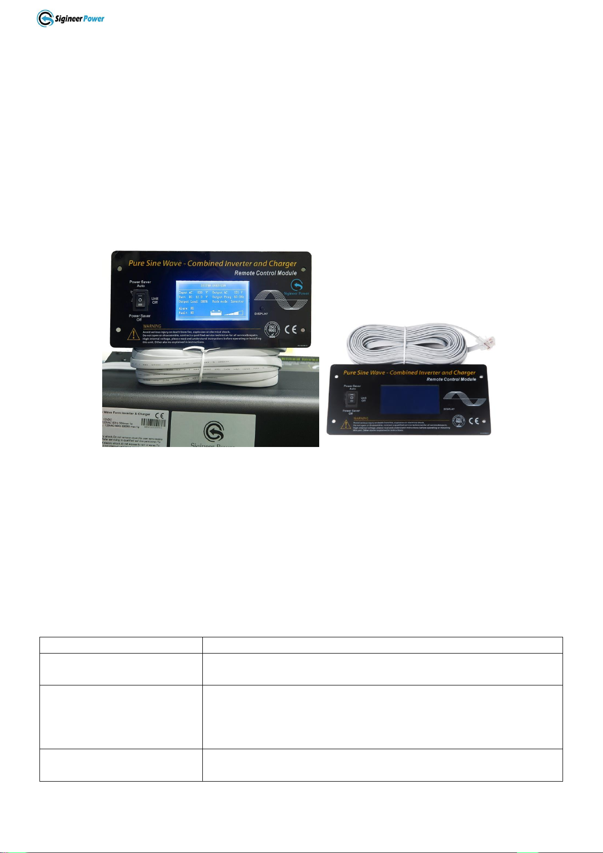
www.sigineer.com
15
Whichever first switches from “Unit Off” to “Power saver off” or “Power saver on”, it will power the
inverter on.
If the commands from the two panels conflict, the inverter will accept command according to the following
priority:
Power saver on> Power saver off> Power off
Only when both panels are turned to “Unit Off” position, will the inverter be powered off.
The suggested length between the switch panel and inverter is 10 meters.
Never cut the remote cable when the cable is attached to inverter and battery is connected to the inverter.
Even the inverter is turned off, this will damage the remote PCB inside if the cable is short circuited during
cutting.
LCD remote control panel(optional).
Note:
When the inverter is in Battery Priority mode, “AC: abnormal”will also be displayed when the inverter
finishes a complete charging circle and switches to inverter mode.
“AC: abnormal”only means the inverter doesn’t accept AC input or there is no AC input, it doesn’t mean
the inverter is abnormal.
In AC mode, the LCD will not display the status of AC load.
2.5.8 Audible Alarm
The inverter also gives audible alarms when the following situations occur.
Battery Voltage Low
Inverter green LED Lighting, and the buzzer beep 0.5s every 5s.
Battery Voltage High
Inverter green LED Lighting, and the buzzer beep 0.5s every 1s,
and Fault after 60s.
Invert Mode Over-Load
(1)110%<load<125%(±10%), No audible alarm in 14 minutes,
Beeps 0.5s every 1s in 15th minute and Fault after 15 minutes;
(2)125% <load<150%(±10%), Beeps 0.5s every 1s and Fault after 60s;
(3)Load>150%(±10%), Beeps 0.5s every 1s and Fault after 20s;
Over Temperature
Heat sink temp. ≥105ºC(221℉), Over temp red LED Lighting, beeps
0.5s every 1s;

www.sigineer.com
16
2.5.9 FAN Operation
For Sigineer Power 1500W-6000W models, there is one multiple controlled DC fan.
The DC fan is designed to operate according to the following logic:
Condition
Enter Condition
Leave condition
Speed
HEAT SINK
TEMPERATURE
T ≤ 60℃(140℉)
T > 65℃(149℉)
OFF
65℃(149℉)≤T < 85 ℃(185℉)
T ≤60℃(140℉) or T ≥ 85℃(185℉)
50%
T > 85℃(185℉)
T ≤80℃(176℉)
100%
CHARGER
CURRENT
I ≤ 15%
I ≥ 20%
OFF
20%< I ≤ 50%Max
I≤ 15% or I > 50%Max
50%
I > 50%Max
I ≤ 40%Max
100%
LOAD Percentage
(INV MODE)
Load < 30%
Load ≥ 30%
OFF
30% ≤ Load < 50%
Load ≤ 20% or Load ≥ 50%
50%
Load ≥ 50%
Load ≤ 40%
100%
Allow at least 30CM of clearance around the inverter for air flow. Make sure that the air can circulate freely
around the unit.
Fan noise level <60db at a distance of 1m.
The transformer is rated at 180 degrees Celsius, special attention should be paid to the hot inverter box
around it. Don’t touch it.
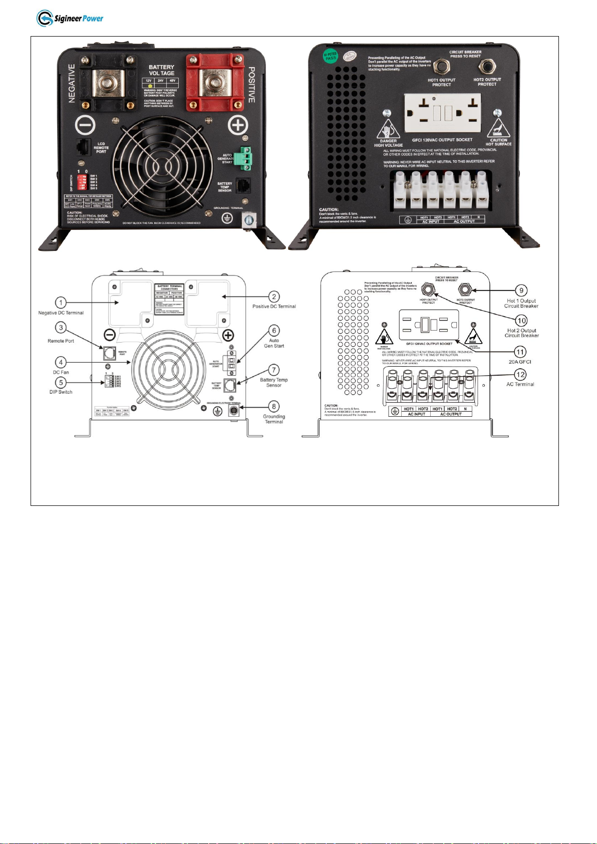
2.5.10 DIP Switches
On the DC end of inverter, there are five DIP switches which enable users to customize the performance of
the device.
Switch #
Switch Function
Position: 0
Position: 1
SW1
Low Battery Trip Point
10/20/40VDC
10.5/21/42VDC
SW2(240Vac)
AC Input Range
176-242Vac±4%
160-264Vac(40Hz+)±4%
SW2(120Vac)
AC Input Range
100-135Vac±4%
90-135Vac(40Hz+)±4%
SW3
Power Save Override ON/OFF
Inverter Off
Power Saver On( 3 sec)
SW4
Frequency Switch
50Hz
60Hz
SW5
Battery/AC Priority
AC Priority
Battery Priority
SW1:Low Battery Trip Point
Deep discharge of the lead acid battery leads to high losses in capacity and early aging. In different
applications a different low voltage disconnection level is preferred. For example, for solar applications,
user may intend to have less DOD to prolong the battery life cycle. While for mobile applications users may
intend to have more DOD to reduce battery capacity and on board weight.
For 12VDC models, the inverter Low Battery Trip Point is selectable at 10.0/10.5VDC.
For 24VDC models, the inverter Low Battery Trip Point is selectable at 20/21VDC.
For 48VDC models, the inverter Low Battery Trip Point is selectable at 40/42VDC.
SW2:AC Input Range
There are different acceptable AC input ranges for different kinds of loads.
For some relatively sensitive electronic devices, a narrow input range of 176-242VAC for 120/240Vac split
phase models (100-135V for 120Vac models) is required to protect them.

www.sigineer.com
17
While for some resistive loads which work in a wide voltage range, the input AC range can be customized to
160-264VAC for 120/240Vac split phase models (90-135V for 120Vac models), this helps to power loads
with the most AC input power without frequent switches to the battery bank.
In order to make the inverter accept dirty power from a generator, when the SW2 is switched to position “1”,
the inverter will bypass an AC input with a wider voltage and frequency (40Hz plus for 50Hz/60Hz).
Accordingly, the AC charger will also work in a wider voltage and frequency range (43Hz plus for
50Hz/60Hz).
This will avoid frequent switches between battery and generator. But some sensitive loads will suffer from
the low quality power.
The pros and cons should be clearly realized.
SW3: Power Save Override ON/OFF
Under the Battery Priority Mode (SW5 in position “1”), the inverter can be switched between two modes:
Power Saver Mode (SW3 in position “1”) and Unit Off Charging Mode (SW3 in position “0”). The power
Switch should be in “Power saver on” position all the time for using these functions.
In Power Saver Mode, the inverter is initially in standby mode and sends a pulse to detect the presence of a
load every 3 seconds. Each pulse lasts for 250ms. The inverter will remain in standby mode until a load has
been detected. Then it will wake up from standby mode and start to invert electricity from the battery bank
to supply the load. As this function is under Battery Priority, the inverter will always prefer to invert
electricity from battery first even there is a qualified AC input present. Only when the battery voltage is
lower than the low voltage alarm point, will the inverter switch to AC input power to charge the battery and
supply the load at the same time.
This Power Saver Mode can be changed to Unit Off Charging mode via SW3 by switching it to “0” position
(SW5 still in “1”).
“Unit Off Charging” will enable the inverter charger to charge batteries as much as possible while without
discharging them.
In “Unit Off Charging” mode, the inverter will stay in standby mode without sensing loads. It won’t output
any power even if a load is turned on, and only stay idle in this mode when there is no AC input.
When a qualified AC input is present, it will start charging the battery and transfer power to loads.
This feature is ideally suitable for applications where energy conservation for batteries is required.
Charging will be activated once qualified AC exists, while discharging is disabled.
The inverter only consumes as little as 3 watts in “Unit Off Charging”mode.
SW4: Output Frequency
The output frequency of the inverter can be set at either 50Hz or 60Hz by SW4 which make the inverter
charger an international models for most electricity systems.
SW5: AC/Battery Priority
The Sigineer Power inverter chargers are designed with AC/Battery priority switch (DIP switch #5).
Switch the battery priority selector to Position “0” for AC priority mode, Position”1” for battery priority
mode. In AC priority mode, when AC input is present, the battery will be charged first, and the inverter will
transfer the input AC to power the load. Only when the AC input is stable for a continuous period of 15 days
will the inverter start a battery inverting cycle to protect the battery. After one normal charging cycle is
completed, ac power bypass will be restored.
When you choose battery priority, the inverter will invert from battery despite the AC input.
When the battery voltage reaches the low voltage alarm point higher than “Low Battery Trip Point”(the
gap between low battery alarm and cut off is 0.5Vdc for 12Vdc, 1Vdc for 24Vdc, 2V for 48Vdc), the
inverter will transfer to AC input, charge battery, and switch back to battery when the battery is fully
charged. This function is mainly for wind/solar systems using utility power or generator as back up.
www.sigineer.com
18
The AC/Battery Priority function can be activated by sliding the switch even when the inverter is in
operation.
Note: In battery priority mode, when qualified AC inputs for the first time and the battery voltage is
below 12.5Vdc (12.5Vdc for 12Vdc, 25Vdc for 24Vdc, 51Vdc for 48Vdc), the inverter will first carry
out a cycle of bulk charging and absorb charging, the inverter will not go into float charging mode.
Choosing the battery type selector to “0”will disable the built-in battery charger while still allow
transfer through. When battery charger is disabled, if the battery is charged by external DC power to
13.5Vdc (13.5Vdc for 12Vdc, 27Vdc for 24Vdc, 54Vdc for 48Vdc), the inverter will go to battery
priority mode again.
2.5.11 Auto Generator Start
The inverter can start up generator when battery voltage goes low.
When the inverter goes to low battery alarm, it will send a signal to start a generator and turn the generator
off after battery charging is finished.
The auto gen start feature will only work with generators which have automatic starting capability. The generator
must have start and stop controls [i.e., an electric starter and electric choke (for gasoline units)], and the safety
sensors to be able to start and stop automatically.
There is an open/close relay (constant open) that will close and short circuit the positive and negative cables from
a generator start control. The input DC voltage can vary, but the max current the relay can carry is 16Amp.
The Auto Generator Start terminal pins are not polarized.
In addition, these two pins can also be used as dry contacts to send out “Low Battery Voltage”signal to an
external alarm device.
This AGS relay can also carry AC voltage within its capacity.
This inverter will skip the float charging when it is set at battery priority mode, so that the generator will no
longer be kept running to maintain a small charge on the batteries.

www.sigineer.com
19
2.5.12 Battery Temperature Sensing
Applying the proper charge voltage is critical for achieving optimum battery performance and longevity. The
ideal charge voltage required by batteries changes with battery temperature.
The battery temperature sensor allows the charge controller to continuously adjust charge voltage based on
actual battery temperature.
Temperature compensation of charge voltage assures that the battery receives the proper charge voltage as
battery temperature varies.
The entire line are compatible with Battery Temperature Sensing for increased charging precision.
It sends precise information to the charger, which automatically adjusts voltage to help ensure full battery
charge depending on the ambient temperature of your battery installation.
When the battery tempreture is over 40℃(104℉), it will reduce the charging voltage by 0.1Vdc with every
degree of temperature rise.
We recommend that you install Battery Temperature Sensors on all banks to protect your batteries and to
provide optimal charging of each bank.
The battery temperature sensor mounts on the side of a battery or any other location where the precise
temperature of battery can be detected such as battery mounting racks.
The following table describes approximately how much the voltage may vary depending on the temperature
of the batteries.
Inverter Condition
Temperature on BTS
Charger Operation
Charger Mode
BTS ≥ 50℃(122℉)
Automatically turns off charger
BTS ≤ 40℃(104℉)
Automatically turns on charger
Inverter Mode
40℃(104℉) ≤ BTS ≤ 50℃(122℉)
Increases the low voltage shut down
point by 0.5Vdc
BTS ≥ 50℃(122℉)
Over Temp Fault
A Battery Temperature Sensor has
been provided as an optional
accessory, it should be bought
separately. It comes with 32.8’/10m
cable.
Important: If the battery temperature is allowed to fall to extremely cold temperatures, the inverter with a
BTS may not be able to properly recharge cold batteries due to maximum voltage limits of the inverter.
Ensure the batteries are protected from extreme temperatures.
For more detailed technical information, please contact us at info@sigineer.com .
2.5.13 GFCI Outlet
For Sigineer Power 1500W to 6000W 120Vac single phase and 120/240Vac split phase models, there is a
GFCI (ground-fault circuit interrupter) outlet in the vicinity of the AC terminal block.

www.sigineer.com
20
The GFCI is an electrical safety device that quickly breaks an electrical circuit with leakage current to
ground. It is to protect equipment and to reduce the risk of serious harm from an ongoing electric shock.
This GFCI is wired in parallel with theAC terminal block and they can output a maximum of nominal
power.
For the 120/240Vac split phase models, the GFCI is installed on the Hot 1 line.
The GFCI amperage rating is 20A for all models.
The GFCI has no overload protection.
2.5.14 Automatic Neutral-to-Ground Bonding
The automatic neutral-to-ground bonding feature uses an internal relay that automatically connects the AC
neutral output to the vehicle/boat’s safety ground (“bonding” it) in Inverter Mode and disconnects it
(“un-bonding” it) when they have connected to a qualified external AC source.
The inverters with model # of APC3012NC/APC3024NC/APC3048NC are equipped with automatic
neutral-to-ground switching.
This design avoids two neutral-to-ground connections from existing at the same time, thereby preventing an
electrical shock hazard between the vehicle/boat’s neutral and the external AC source’s neutral.
Disabling the Automatic Neutral-to-Ground Connection
In some installations, this feature must be disabled.
This manual suits for next models
15
Table of contents
Other Sigineer Power Batteries Charger manuals


Popular Batteries Charger manuals by other brands


LEAB
LEAB CHAMP 12 V user manual

VOLTCRAFT
VOLTCRAFT VC-30WC-PD operating instructions

PRO Charging System
PRO Charging System i2412 Safety, installation and operating instructions

CTEK
CTEK CHARGESTORM CONNECTED 2 user manual

Genius
Genius G4 Owner's manual & user guide

Schumacher Electric
Schumacher Electric SC-300A Quick steps