Sigma V KT848 User manual

Sigma V
KT848 Business Telephone
System
Installation Guide
(Release 1.1)

i
CONTENTS
I. System Overview...............................................................................1
i. System Operation........................................................................................1
ii. System Configuration...................................................................................1
iii. Hardware Diagram.......................................................................................2
1. Main Unit...............................................................................................2
2. Power Supply........................................................................................2
3. Mother Board........................................................................................3
4. 4 ports CO line board (CO 1~4)............................................................3
5. 4 ports CO line expansion board (CO 5~8)...........................................4
6. Caller ID board......................................................................................4
7. 8 ports Extension expansion board.......................................................4
8. Feature phone ......................................................................................5
9. DSS Console........................................................................................6
II. Specifications.....................................................................................7
i. System Capacity..........................................................................................7
ii. Power Specifications....................................................................................7
iii. Environmental Limits....................................................................................7
iv. Cable Requirements ....................................................................................7
v. Physical Dimensions and Weights...............................................................7
vi. Peripheral.....................................................................................................8
III. Installation....................................................................................9
i. Main unit installation .............................................................................9
ii. Power Supply installation....................................................................10
iii. Co line connection .............................................................................. 11
iv. Station connection .............................................................................. 11
v. CO line expansion board installation................................................... 11
vi. Extension expansion board installation...............................................12
vii. Caller ID board....................................................................................12
viii. External Music-On-Hold installation....................................................13
ix. External Speaker installation ..............................................................13
x. SMDR installation ...............................................................................14
xi. Power Failure Transfer installation......................................................14

ii
IV. System Programming................................................................16
i. Numerical Program Overview....................................................................16
ii. Alphabetical Program Overview.................................................................17
iii. Ways of using feature phone to access system programming:..................18
iv. Ways of using the single line phone to access system programming: .......18
Program 00: Time and Date Settings......................................................19
Program 01: CO setting #1......................................................................19
Program 02: CO setting #2......................................................................20
Program 03: System speed dialing ........................................................20
Program 04: System setting #1...............................................................21
Program 05: System setting #2...............................................................21
Program 06: System setting #3...............................................................22
Program 07: System setting #4...............................................................22
Program 08: Night transfer......................................................................23
Program 09: Outgoing call setting (Day mode).....................................23
Program 10: Outgoing call setting (Night mode) ..................................23
Program 11: Incoming call setting (Day mode).....................................24
Program 12: Incoming call setting (Night mode) ..................................24
Program 13: Setting of delay ringing / DISA setting.............................24
Program 14: Class of Service .................................................................25
Program 15: Restriction code A .............................................................25
Program 16: Restriction code B .............................................................26
Program 17: Unrest code C.....................................................................26
Program 18: Public restriction code D...................................................26
Program 19: PBX access code ...............................................................27
Program 20: Account code setting.........................................................27
Program 21: DISA (Trunk-to-trunk transfer) access code setting .......28
Program 22: Extension setting #1..........................................................28
Program 23: Extension setting #2..........................................................29
Program 24: Pickup group assignment .................................................29
Program 25: Executor (Boss) /Secretary function................................30
Program 26: System password...............................................................30
Program 27: Special port setting............................................................31
Program 28: Initialize the system...........................................................31
Program 29: Extension number assignment.........................................32
Program 30: Unit price setting of international distance call...............32
Program 31: Unit price setting of domestic distance call ....................32
Program 32: Unit price setting of local call ...........................................32

iii
Program 33: Displaying of telephone charges......................................33
Program 34: Review password of extension lock.................................33
Program 35: Review system charge counting.......................................33
Program 36: Presetting call charges......................................................34
V. Sample for special feature...............................................................35
VI. Station Operation.......................................................................40
VII. Troubleshooting.........................................................................43
1.1 System down .............................................................................................44
1.2 Station Dial Tone Faults.............................................................................44
1.3 CO Line Dial Tone Faults...........................................................................44

Page 1
I. System Overview
i. System Operation
Sigma V KT848 system is a stored program controlled electronic key telephone
system ready to use as soon as it is turned on. A powerful microprocessor digitally
controls all speech paths and system functions. The operating program with default
memory is stored in non-volatile ROM. Customer data is stored in RAM and protected
by a Ni-Cd battery for up to at least one month’s continuous loss of system power.
When AC power is restored, the Ni-Cd battery will be recharged.
ii. System Configuration
Sigma V KT848 system has a basic capacity of 4 CO line ports and 16 extension ports,
which can be extended to 8 CO and 48 extensions in maximum by adding optional
expansion boards. This system can be used for both feature phones and single line
phones. Extension ports 1 to 4 are assigned for either feature phone or single line
phones. The extension ports can be connected with single line phones as well as
faxes, recording machines and cordless phones etc.
Sigma V KT848 system has three kinds of expansion boards:
y4 ports CO line expansion board (1 pc. expandable at max.)
y8 ports Extension expansion board (4 pcs. expandable at max.)
y7 ports Caller ID board (1 pc. at maximum)
Combining the strapping options of basic KSU with all the combinations of expansion
boards, Sigma V KT848 system is extremely flexible. The maximum numbers of each
circuit type available in a fully configured Sigma V KT848 system are listed below.
Circuit Type Maximum Number Available
Feature Phone 4
Single Line Phone 48 (if no any feature phone)
CO Line (Loop Start) 8
Remarks: Two features will reduce the system capacity:
1. Caller ID occupy 1 CO port
2. DISA Trunk-to-Trunk occupy 1 Ext port

Page 2
iii. Hardware Diagram
1. Main Unit
2. Power Supply

Page 3
3. Mother Board
(1) 4 ports CO line board terminal (CO 1~4)
(2) 4 ports CO line expansion board terminal (CO 5~8)
(3) 8 ports Extension expansion board terminal (017~024)
(4) 8 ports Extension expansion board terminal (025~032)
(5) 8 ports Extension expansion board terminal (033~040)
(6) 8 ports Extension expansion board terminal (041~048)
(7) Jumper for internal/external music selection
(8) External music input for MOH
(9) External paging output
(10) Parallel interface (Printer)
(11) Serial interface (PC)
4. 4 ports CO line board (CO 1~4)

Page 4
5. 4 ports CO line expansion board (CO 5~8)
6. Caller ID board
7. 8 ports Extension expansion board

Page 5
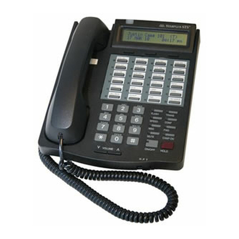
8. Feature phone
(1) Handset
(2) LCD display
(3) Flexible/function buttons: red/green LED indicators
Button 1~8: Co line
Button 9~32: One touch key for station or outside telephone number
Button 33: FNC
Button 34: CLEAR
Button 35: DND
Button 36: SCROLL
(4) Dial pad
(5) Panel display light switch
(6) Fixed buttons
/ : Volume up / down
(7) Handset socket
(8) Telephone set socket
(9) DSS1 terminal
(10) Not use
(11) Microphone
(12) Speaker

Page 6
9. DSS Console
(1) DSS button
Button 1~48:extension port 001~048
Button 49~64: not use
(2) DSS terminal

Page 7
II. Specifications
i. System Capacity
A maximum of 56 ports: the sum of CO/PBX lines and extension lines.
Basic: 4 up to 8 CO/PBX lines (Loop Start, 600 ohms)
4 Feature phones
16 up to 48 Single line phones
Additional: 3 Speech Paths
2 Audio Channels for Music (One of Internal Melody and the other of
External)
1 Audio Channel for External Speaker
ii. Power Specifications
Power supply voltage: 180 VAC to 264 VAC, 50/60 Hz
Maximum power consumption: 80 W
Cross-talk attenuation: 70 dB
Transmission loss: 0.37 dB
Battery backup supply: 24VDC Batteries rating not less than 7Ah but not more
than 40Ah
iii. Environmental Limits
Operating temperatures: 0 °C to 45 °C (32 °F to 113 °F)
Operating humidity: 10% to 95% without condensation
iv. Cable Requirements
Feature phone: Maximum 100m (2 pairs twisted wire 0.5@)
Single line phone: Maximum 1,000m (1 pair twisted wire 0.5@)
v. Physical Dimensions and Weights
Key Service Unit: 485mm W x 300mm H x 110mm D, 10.0Kg
Feature phone: 230mm W x 95mm H x 210mm D, 1.0Kg
66-Key Direct Access Console: 230mm W x 80mm H x 160mm D, 1.0Kg

Page 8
vi. Peripheral
SMDR Communications: 1,200 baud rate, 8-N-1
Source of music: Input impedance: 600 ohms
Input audio level: generally 250MV, virtual value 1V at
the most
Sound amplification output: Input impedance: 600 ohms
Input audio level: generally 250MV, maximum 400MV

Page 9
III. Installation
System installation is shown as below:
i. Main unit installation
Remark:
- Make sure that have enough space to open the cover of Main Unit, switch on/off
power and make a connection with parallel interface
- Measure the length between two holes for wall mount, and then drill and put it on the
wall
- Put the ground terminal connect to earth through ground wire

Page 10
ii. Power Supply installation
There are 2 kind of power supply –Type1) Standard Type2) Specify for backup
battery.
Type1) Standard
(1) AC input of Transformer
(2) AC output of Transformer which plug-in to (3)
1. Yellow wires – 70 VAC
2. Blue wires – 14 VAC
3. Black wires – 26 VAC
(3) AC input of Linear power panel terminal
(4) DC output of Linear power panel plug-in to main board
zPin 1 & 2 – 70 VAC
zPin 1 & 3 – 5 VDC
zPin 1 & 4 – 12 VDC
zPin 1 & 5 – 30 VDC
(5) Power LED terminal
Type2) Specify for backup battery
(1) Same as (1) of Type1
(2) AC output of Transformer which plug-in to (3)
zBlack wires – 30 VAC
(3) Same as (3) of Type1
(4) Same as (4) of Type1
(5) Same as (5) of Type1
(6) Backup battery input

Page 11
iii. Co line connection
iv. Station connection
Feature phone
(Remark: max. 100m length between extension port and telephone set socket)
Single line phone
(Remark: max. 1000m length between extension port and telephone set socket)
v. CO line expansion board installation

Page 12
vi. Extension expansion board installation
vii. Caller ID board

Page 13
viii. External Music-On-Hold installation
ix. External Speaker installation

Page 14
x. SMDR installation
Pin assignment of (2): KSU PC
2 →3
3 →2
7 →5
xi. Power Failure Transfer installation

Page 15
Notes
1. The Sigma V KT848 system should be installed in a place away from vibration and
moisture, which is clean, dry and ventilated. Do not either put sundries on the KTU
or block its vent hole.
2. While you are wiring the extensions, it is a good idea to mask the wires off the power
line and other high frequency links or keep them at least 1m away.
3. When the crystal heads (RJ11) of all the extensions are compressed, please check
whether the heads are properly connected to the telephone lines to make sure all
the contacts work properly and whether the crystal heads and their bases are loose
or not.
4. The feature phone is provided with one connecting line of four cores; if you want to
make it longer, please be careful with the order of the four cores, where the two in
the middle are for signaling and the two in both sides for data transmission. If you
need to add more crystal heads for joints, please refer to the diagram (if the
operating distance of the feature phone connecting line is less than 100m, while
compressing the crystal heads for joints, you must disconnect the connecting line
from the host).
5. Be sure that the power plug of the KTU is properly plugged into the power socket.
Do not share the power socket with other equipment such as air conditioner and
electric motor etc.
6. When the system is fixed, switch on the power, and the working voltage is 220VAC
(please refer part II in details).
7. See to the power, backup power inclusive, is switched off when any component
except for the plugging and unplugging of the crystal heads of the inside and
outside lines inside the system is to be altered. It is suggested no lines be
connected to the extension ports, which are in no use.
8. The KTU must be connected to ground for fear of thunder stroke. Be sure that the
ground wire is in proper contact with the ground so as to make the most of the
lightening proof function of the system.

Page 16
IV. System Programming
i. Numerical Program Overview
Program Code Program Title
0 0 Time and Date Settings
0 1 CO setting #1
0 2 CO setting #2
0 3 System speed dialing
0 4 System setting #1
0 5 System setting #2
0 6 System setting #3
0 7 System setting #4
0 8 Night transfer
0 9 Outgoing calls setting (Day mode)
1 0 Outgoing calls setting (Night mode)
1 1 Incoming calls setting (Day mode)
1 2 Incoming calls setting (Night mode)
1 3 Setting of delay ringing / DISA setting
1 4 Class of Service
1 5 Restriction code A
1 6 Restriction code B
1 7 Unrest code C
1 8 Public restriction code
1 9 PBX access code
2 0 Account code setting
2 1 DISA (Trunk-to-trunk transfer) access code setting
2 2 Extension setting #1
2 3 Extension setting #2
2 4 Pickup group assignment
2 5 Executive (Boss) / Secretary function
2 6 System password
2 7 Special port setting
2 8 Initialize the system
2 9 Extension number assignment
3 0 Unit price setting of international distance call
3 1 Unit price setting of domestic distance call
3 2 Unit price settings of local call
Table of contents
Popular Telephone System manuals by other brands
Panasonic
Panasonic KX-TDA600 - Hybrid IP PBX Control Unit Max. 1008... Programing manual
Syscom Video
Syscom Video AV Series user guide

Lucent Technologies
Lucent Technologies R4.2 Administration
SpectraLink
SpectraLink SCA408 Installation
LG-Nortel
LG-Nortel Aria-24IP user guide
Xblue Networks
Xblue Networks X16 quick start guide
