AIR CIRCUIT BREAKERS
www.sigmaelektrik.com
7
ACB
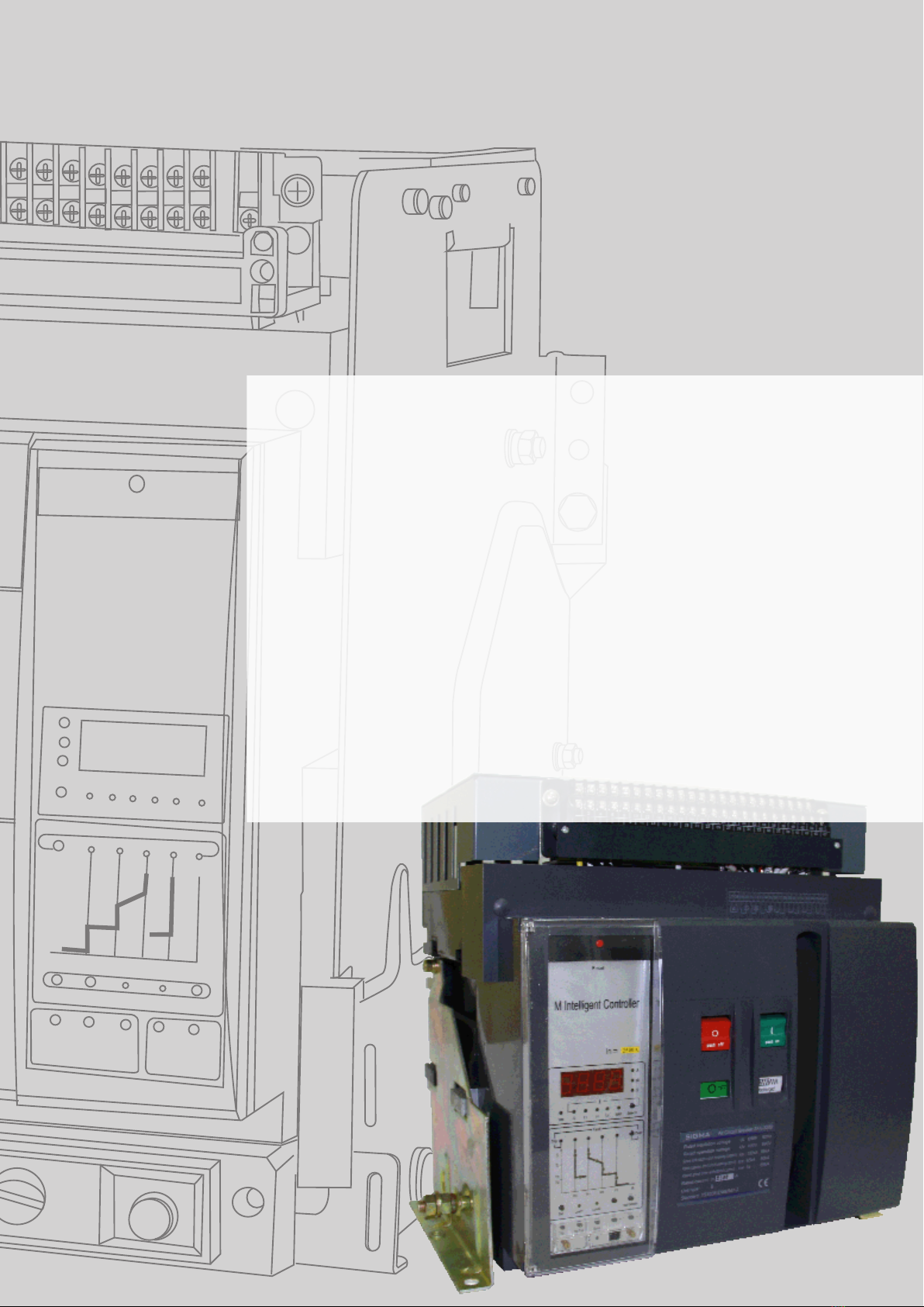
Intelligent controller
Panel caption:
1. Reset button for fault releasing
2. Rated current of the breaker
3. Unit of voltage
4. Voltage indicator
5. Voltage of each line and the min, value
6. Key for selecting voltage
7. Current-time indicator
8. Unit of current and time
Indication of three phase current, neutral phase current,
grounding fault-current and the max. value
9. Key for selecting current
10. "clean " key
11. Fault showing for instantaneous
12. Fault showing for over-load short-delay
13. Fault showing for over-load long-delay
14. Fault showing for earthed error
15. Showing the long-delay current setting
(alarm simultaneously)
16. Showing the long-delay action time setting
17. Showing the short-delay current setting
(alarm simultaneously)
18. Showing the short-delay action time setting
19. Showing the instantaneous current setting
(alarm simultaneously)
20. Key for inspecting fault
21. Key for detecting wearing of contacts
22. Load supervision signal 2 (alarm simultaneously)
23. Load supervision signal 1 ( alarm simultaneously
24. Setting's decrease progressively
25. Setting's increase progressively
26. Supply socket ( DC24V) for test power
27. Memory key
28. Memory indicator
29. Non-release test key
30. Release test key
31. Setting key for various protection value
32. Indication of the earthed fault action time setting
33. Indication of the earthed fault current setting
(alarm simultaneously)
34. Release indicating
35. Test indicating
Other function:
1. Auto-diagnosis
2. Thermo-simulation
3. Fault-memory
4. MCR
The panel here in belongs to the circuit breaker of four poles,
If the breaker is of three poles, the mark IN in item 9 indicating
current of neutral phase will disappear. Other than the type
M intelligent controller with voltage indication, the other one
without voltage indication is also available (there aren't items 3,
4, 5 and 6 on the panel in this case).
NOTE: