Sigmann DELTA SDVM125ex User manual

Sigmann DELTA GmbH Tel. 06268-92899-73 Handelsregister Volksbank Kraichgau
Hauptstraße 53 Fax 06268-92899-74 Mannheim HRB 703603 BLZ 672 922 00 Konto 55258007
UstIDNr: DE257944309 http://www.sigmann-delta.de Joachim Kraus IBAN DE31 6729 2200 0055 2580 07
Date: 17.02.2016
Operating Instructions
Power supply SDVM125ex
Type SD.211.XXX1.00

SDVM125ex_BA_en_003

SDVM125ex_BA_en_003
Table of contents
1 Overview - Power supply for use with wired handheld scanner Zone 1 2
2 Overview - Power supply for use with Bluetooth scanner Zone 1 3
3 Important Notes on the Operating Instructions 4
3.1. Safety information ......................................................................................... 4
3.2 Notes on the Operating Instructions ......................................................................................... 5
3.3 General Caution ......................................................................................... 6
4 Product Information 8
4.1 Explosion protection ....................................................................................... 8
4.2 Technical Data explosion protection ....................................................................................... 8
4.3 Type Numbers ...................................................................................... 12
4.4 Serial Numbers ...................................................................................... 12
4.5 Application ...................................................................................... 12
5 Introduction to Operation of the Power Supply 13
5.1 Information on the design of the power supply ................................................ 13
5.2 Pin assignment in the Ex-e connection box RS232 and USB ................................................ 14
5.3 Pin assignment in the Ex-i connection box RS232 ................................................ 15
5.4 Pin assignment in the Ex-i connection box USB ................................................ 16
6 Attachment 17
6.1 EC type examination certificate SDVM125ex ................................................................... 17
6.2 Certificate of Confirmity power supply SDVM125ex ................................................................... 23
7 Contact 30
SDVM125ex_BA_en_003 2
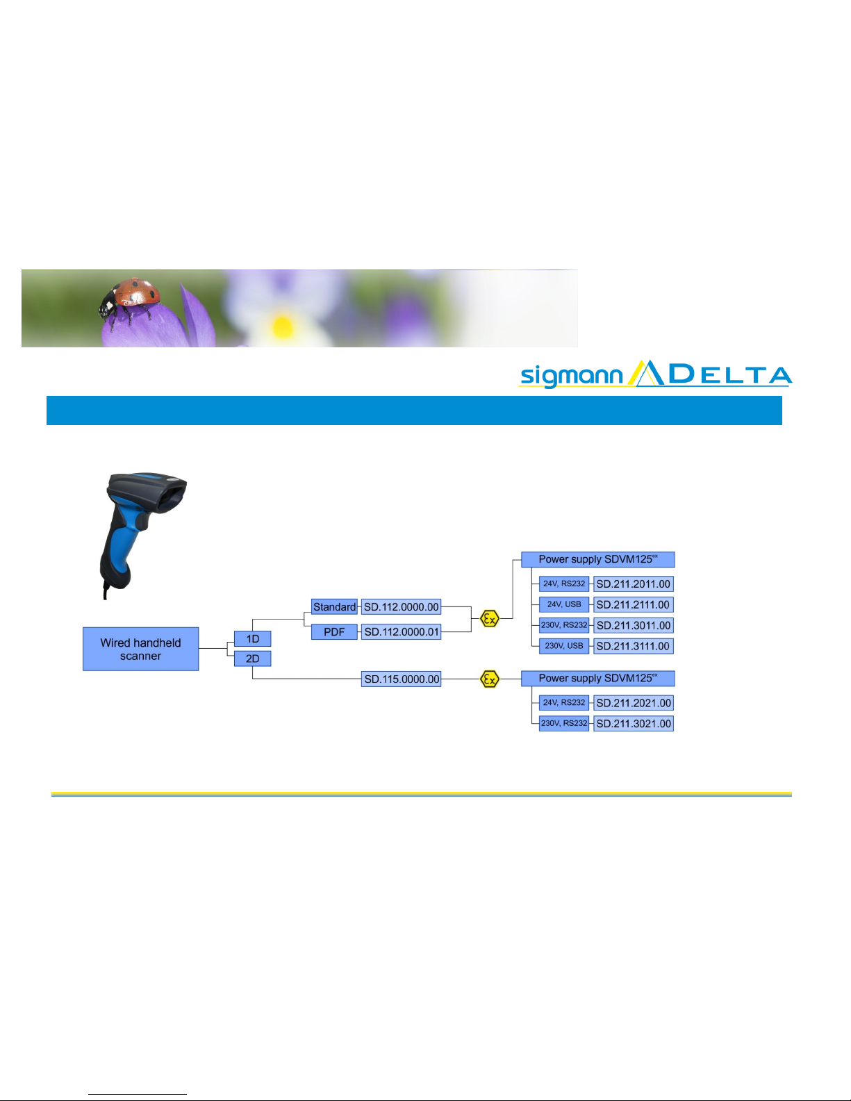
1 Overview - Power supply for use with wired handheld scanner Zone 1

SDVM125ex_BA_en_003 3
2 Overview - Power supply for use with Bluetooth scanner Zone 1
SDVM125ex_BA_en_003 4
3Important Notes on the Operating Instructions
3.1 Safety information
Warnings are highlighted by a special symbol and a different font colour.
Danger
Non-compliance may result in life-threatening situations.
This warning must be heeded.
Warning
This type of warning concerns dangerous situations that may result in light or small inju-
ries.
Info
Important and helpful notes and information.

SDVM125ex_BA_en_003 5
3.2 Notes on the Operating Instructions
Before starting up the equipment please read the Manual thoroughly.
The Operating Instructions contain important information on functionality as well as safety rules. If these
are not heeded, normal operations within hazardous areas cannot be guaranteed.
The notes contained in this manual are important for starting up and operating the product.
These instructions may be updated at any time. Sigmann DELTA GmbH reserves the right to make changes to
this document.
Before using the product, users must ensure that they have the most up-to-date version of the operating instruc-
tions. To be sure this is the case, please check Sigmann DELTA's website at www.Sigmann-DELTA.de or contact
one of the company's staff.
The drawings contained in these operating instructions are for illustration purposes only and may differ somewhat
from the actual design.
No changes may be made to the device that were not intended or approved
by Sigmann DELTA.
Incorrect handling of the device may result in the termination of the operating permit for hazardous areas.
Non-adherence to the instructions will void any warranty.

SDVM125ex_BA_en_003 6
3.3 General caution
Caution / Notes
The devices may only be operated when fully assembled.
The device must be switched off immediately if it is likely that as a consequence
of damaging impact or general peculiarities the device can no longer be safely
operated. (e.g. ingress of water or other fluids, temperatures outside of the
specified range,...)
General statutory requirements or health and safety rules and accident preven-
tion guidelines and environmental laws must be adhered to (e.g. the German
Occupational Health and Safety regulation).
Users must not open the device.
Users must not make any changes to the device. Components may not be ex-
changed or replaced. If non-specified components are used, explosion protec-
tion is no longer guaranteed.
If the enclosure is in any way damaged, the device must be removed from the
hazardous area immediately.
In accordance with IEC 60079-19 and IEC 60079-17, operators of electric
plants in hazardous areas are obliged to have them serviced by qualified elec-
tricians.
Do not insert any sharp objects into the enclosure or any other openings of the
power supply. Any openings at the device must not be covered or blocked.
The device and any accessories must be properly disposed of, i.e. as legally
specified, for example by a certified company.
Notes on installation
Electrical plants are subject to certain regulations concerning installation and
operation (e.g. RL 99/92/EG, RL 94/9EG, or the national rules such as
IEC 60 079-14 and VDE 0100).
In the hazardous area it is the operator's responsibility to carry out any repair
and maintenance in compliance with applicable rules.

SDVM125ex_BA_en_003 7
Maintenance
Provided the device is operated and assembled according to instructions and
the ambient requirements are being met continuous maintenance is not neces-
sary.
Servicing
Operators of electric equipment in hazardous areas are obliged to have them
serviced by qualified electricians (IEC 60079-19 and IEC 60079-17).
Repairs
Repairs may only be carried out by the manufacturer or by persons trained and
commissioned for this purpose by the manufacturer.
The device is closed ex-factory. It may only be opened in the factory by specifically trained personnel.
Operation
Before operating the device you must ensure that all necessary components are
available.
SDVM125ex_BA_en_003 8
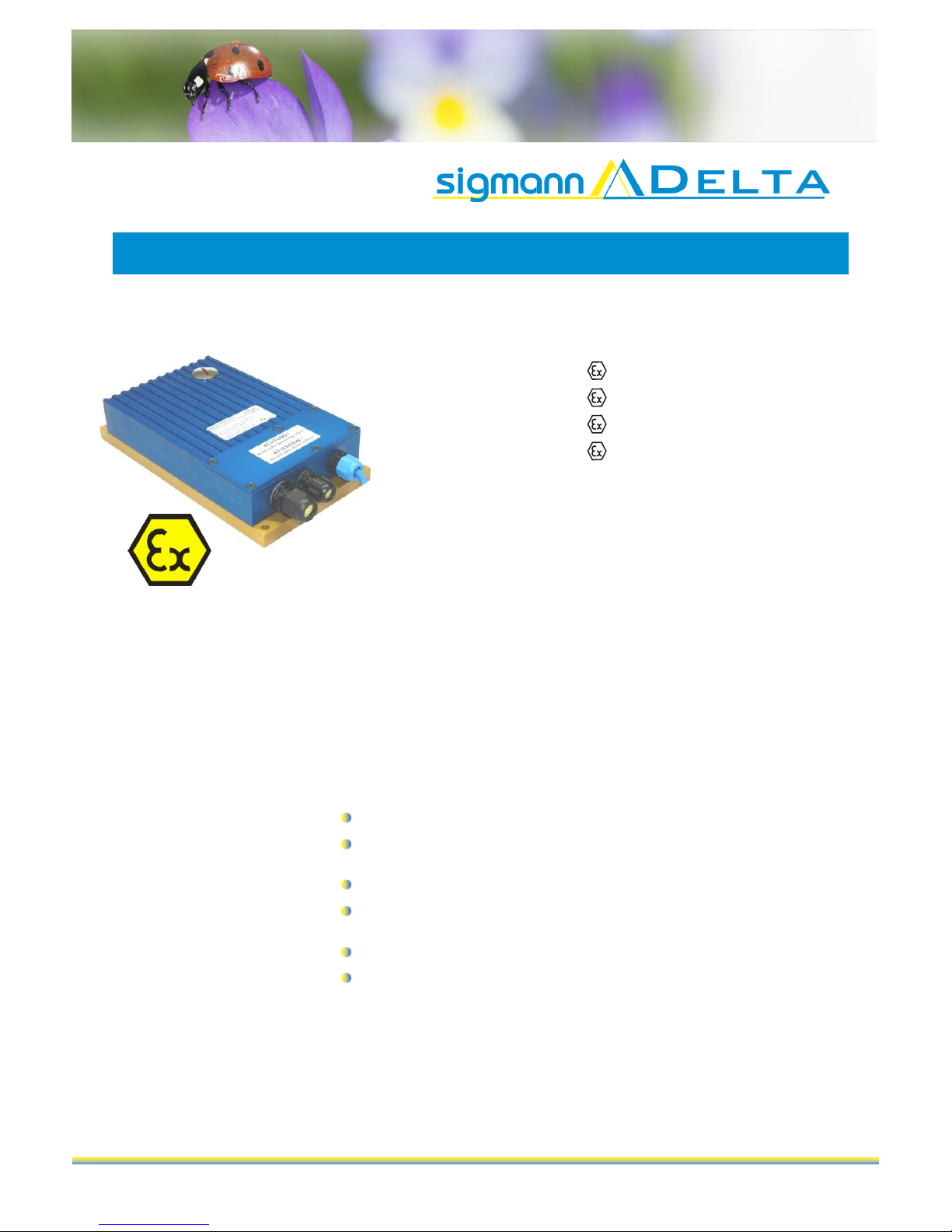
4Product information - SDVM125ex Type SD.211XXX1.00
SDVM215ex Power Supply
4. Explosion
protection
II 2G Ex eb qb [ib IIC/IIB] IIC T4
II 2D Ex tb [ib] IIIC T135°C
II 2G Ex e q [ib IIC/IIB] IIC T4 Gb
II 2D Ex tb [ib] IIIC T135°C Db
-25°C ≤ Ta ≤ +60°C
Certification
IBExU09ATEX1051
IECEx IBE 15.0018
Protection category
IP65
Manufacturer
Sigmann DELTA GmbH
Hauptstraße 53
74928 Hüffenhardt
Germany
4.2 Technical data explosion protection
Non-intrinsically safe supply circuit
SD.211.1XX1.00
Rated voltage UNDC +12 V ± 10 %
Power input P = ca. 3,3W (max. 6,6W)
SD.211.2XX1.00
Rated voltage UNDC +24 V ± 25 %
Power input P = ca. 3,7W (max. 7,1W)
SD.211.3XX1.00
Rated voltage UNAC 90 V to 253 V, 50 - 60 Hz
Power input P = ca. 4W (max. 16W)
Non-intrinsically safe data circuit
SD.211.XXX1.XX
RS232
RS422
USB
±12 V / 4 mA
+12 V / -7 V / 4 mA
+5 V / 68 mA

SDVM125ex_BA_en_003 9
Nominal data RS232-Version
Type
SD.211.X001.00 - with RS232 interface, 5,5V, output current 220mA
Intrinsically
safe supply circuit
Maximum fault voltage Um= 253 V
Maximum output voltage Uo = 5,5V
Maximum output current lo= 440 mA
Maximum output power Po= 1,25 W
Maximum external capacitance Co= 55 µF
Maximum inner capacitance Ci= 2,2 µF
Maximum external inductance L0= 0,1 mHF
Type
SD.211.X011.00 - with RS232 interface, 4,9V, output current 240mA
Intrinsically
safe supply circuit
Maximum fault voltage Um= 253 V
Maximum output voltage Uo = 4,9V
Maximum output current lo= 440 mA
Maximum output power Po= 1,25 W (trapezoidal characteristic)
Maximum external capacitance Co= 113 µF
Maximum inner capacitance Ci= 2,2 µF
Maximum external inductance L0= 0,1 mH
Type
SD.211.X021.00 - with RS232 interface, 4,9V, output current 420mA
Intrinsically
safe supply circuit
Maximum fault voltage Um= 253 V
Maximum output voltage Uo= 4,9V
Maximum output current lo= 750 mA
Maximum output power Po= 2,01 W (trapezoidal characteristic)
Maximum external capacitance depends on type of protection
Ex ib IIC Co ≤ 113µF (Lo=0)
Ex ib IIB Co≤ 250µF (Lo=0)
Maximum inner capacitance Ci= 2,2 µF
Maximum external inductance Lo= 0,1mH (Co=0)

SDVM125ex_BA_en_003 10
Nominal data USB-Version
Type
SD.211.X111.00 - with USB interface, 4,9V 240mA
Intrinsically
safe supply circuit
Maximum output voltage Uo = 4,9 V
Maximum output current lo= 440 mA
Maximum output power Po= 1,20 W (trapezoidal characteristic)
Maximum external capacitance Co= Co VCC + Co DATA =113 µF
Maximum inner capacitance Ci= 2,2 F
Maximum external inductance L0= 0,1 mH
Intrinsically
safe data circuit USB
Maximum output voltage UO D+/D- = 4,9 V
Maximum output current IO D+/D- = 40 mA
Maximum output power PO D+/D- = 48 mW (linear characteristic)
Maximum external capacitance Co= Co VCC + Co DATA =113 µF
Maximum inner capacitance Ci= 1,2 F
Maximum external inductance L0= 0,1 mH
Pin assignment data circuit
Non-intrinsically
safe data circuit
SD.211.X0X1.XX
RS232
X5 (TxD)
X4 (GND)
RS232 ± 12V / 4mA
RS422
X7 (T+)
X8 (T-)
X6 (PE)
RS422 ± 12V / -7V / 4mA
SD.211.X1X1.XX
USB
X5 (screen)
X4 (GND)
X6 (NV)
X7 (D+ 2MA)
X8 (D- 2MA)
USB +5V / 68 mA

SDVM125ex_BA_en_003 11
Intrinsically
safe data circuit
SD.211.X0X1.XX
RS232
X9 (RxD)
X10 (GND)
Ui= 5,5V DC
SD.211.X111.XX
USB
X9 (D+ 2SL)
X10 (D- 2SL)
X11 (GND/PE)
UO D+/ D- = 4,9 V
IO D+/ D- = 20 mA per data cable
PO D+/ D- = 24 mW per data cable
linear characteristic
External connection cable
Data cable
USB: 2,0 - 2,5 mm2, 4-wire
or RS232: 0,2 - 2,5 mm23-wire
Power supply cable
0,2 - 2,5 mm23-wire
The current rating of the connection cables must be checked before use.
General technical data
Dimensions
140 mm x 250 mm x 56 mm (W x H x D)
Weight
3,1 kg (without connection cable)
Ambiente temperature
-25°C to +60°C

SDVM125ex_BA_en_003 12
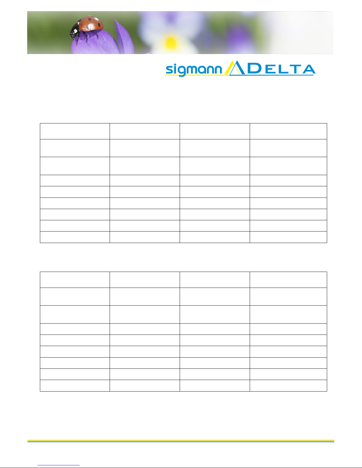
4.3 Type numbers
RS232 devices
SD.211.1001.00
DC 12 V with RS232 interface, Ua= 5,5 V / Ia=220 mA
SD.211.1011.00
DC 12 V with RS232 interface, Ua= 4,9 V / Ia=240 mA
SD.211.1021.00
DC 12 V with RS232 interface, Ua= 4,9 V / Ia=420 mA
SD.211.2001.00
DC 24 V with RS232 interface, Ua= 5,5 V / Ia=220 mA
SD.211.2011.00
DC 24 V with RS232 interface, Ua= 4,9 V / Ia=240 mA
SD.211.2021.00
DC 24 V with RS232 interface, Ua= 4,9 V / Ia=420 mA
SD.211.3001.00
AC 90 to 253 V with RS232 interface, Ua= 5,5 V / Ia=220 mA
SD.211.3011.00
AC 90 to 253 V with RS232 interface, Ua= 4,9 V / Ia=240 mA
SD.211.3021.00
AC 90 to 253 V with RS232 interface, Ua= 4,9 V / Ia=420 mA
USB devices
SD.211.1111.00
DC 12 V with USB-interface, Ua= 4,9 V / Ia=240 mA
SD.211.2111.00
DC 24 V with USB-interface, Ua= 4,9 V / Ia=240 mA
SD.211.3111.00
AC 90 up to 253 V with USB-interface, Ua= 4,9 V / Ia=240 mA
4.4 Serial numbers
Serial number key: year of manufacture production number
2 digits 4digits
Example: 130001
4.5 Application
The purpose of the power supply is the intrinsically safe supply of power to other devices.
The SDVM 125ex (SD.211.XXX1.00) power supply can supply power in hazardous areas zone 1 and 21.

SDVM125ex_BA_en_003 13
5Introduction to Operation of the Power Supply
5.1 Information on design of the power supply
Use the four fixing holes at the corners of the base plate
(see diagram) to mount the power supply onto a firm sur-
face.
The holes have a diameter of 7mm each.
The equipotential bonding connection (M 5 x 10) is locat-
ed at the front and back of the power supply.
Equipotential bonding is required for the en-
tire installation of the intrinsically safe circuits.
Terminal connection box underneath cover.
Cable gland M16 x 1.5 for appliance.
Cable gland M16 x 1.5 for data transfer.
Cable gland M20 x 1.5 for voltage supply.
Ex-e connection box for connection of voltage supply
and data cable to PC.
Ex-i connection box for connection of appliances
SDVM125ex_BA_en_003 14
5.2 Pin assignment in the Ex-e connection box for the supply of the SDVM 125ex
Pin assignment for the supply with RS232 interface (SD.211.X0X1.00)
Terminal definition
Terminal number
Description
Type numbers
+ / - L
X1
L = AC 100 V to 250 V
+ = DC24 V
SD.211.30X1.00
SD.211.20X1.00
- / N
X2
N Neutral conductor
-minus
SD.211.30X1.00
SD.211.20X1.00
PE
X3
PE
GND
X4
RS232
TxD
X5
RS232
Shield
X6
RS232/RS422
T+
X7
RS422
T-
X8
RS422
Pin assignment of supply with USB interface (SD.211.X1X1.00)
Terminal definition
Terminal number
Description
Type numbers
+ / - L
X1
L = AC 100 V to 250 V
+ = DC24 V
SD.211.31X1.00
SD.211.21X1.00
- / N
X2
N Neutral conductor
-minus
SD.211.31X1.00
SD.211.21X1.00
PE
X3
PE
GND
X4
USB
Shield
X5
USB
NC
X6
D+
X7
USB
D-
X8
USB
SDVM125ex_BA_en_003 15
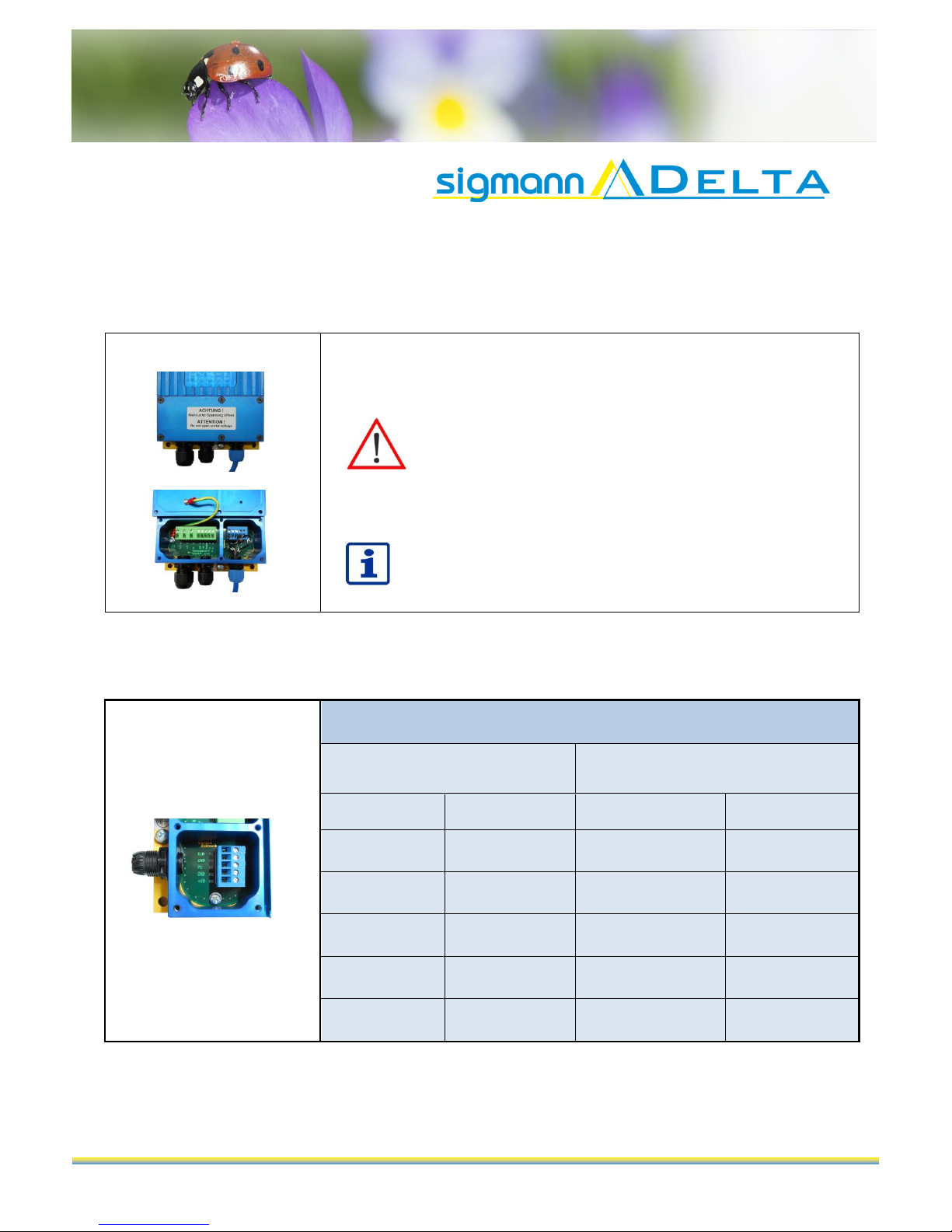
5.3 Pin assignment in the Ex-i connection box of the SDVM125ex
with RS232 interface (SD.211.X0X1.00)
The terminal assignment is located underneath the removable cover at the front of the
power supply.
Caution!
Do not open enclosure in hazardous area!
Before operating the device in a hazardous area you have to ensure that the enclosure
has been closed fully and all screws have been tightened.
Any changes to the wiring may only be carried out by trained staff.
Pin assignment in the Ex-i connection box RS232
Power supply Type: SD.211.X0X1.00
Prepared
Connection coupling
Connection box
Pin
Wire
Definition
Number
3
3
RxD
X9
GND
X10
PE
X11
2
2
GND
X12
1
1
+UB
X13
SDVM125ex_BA_en_003 16
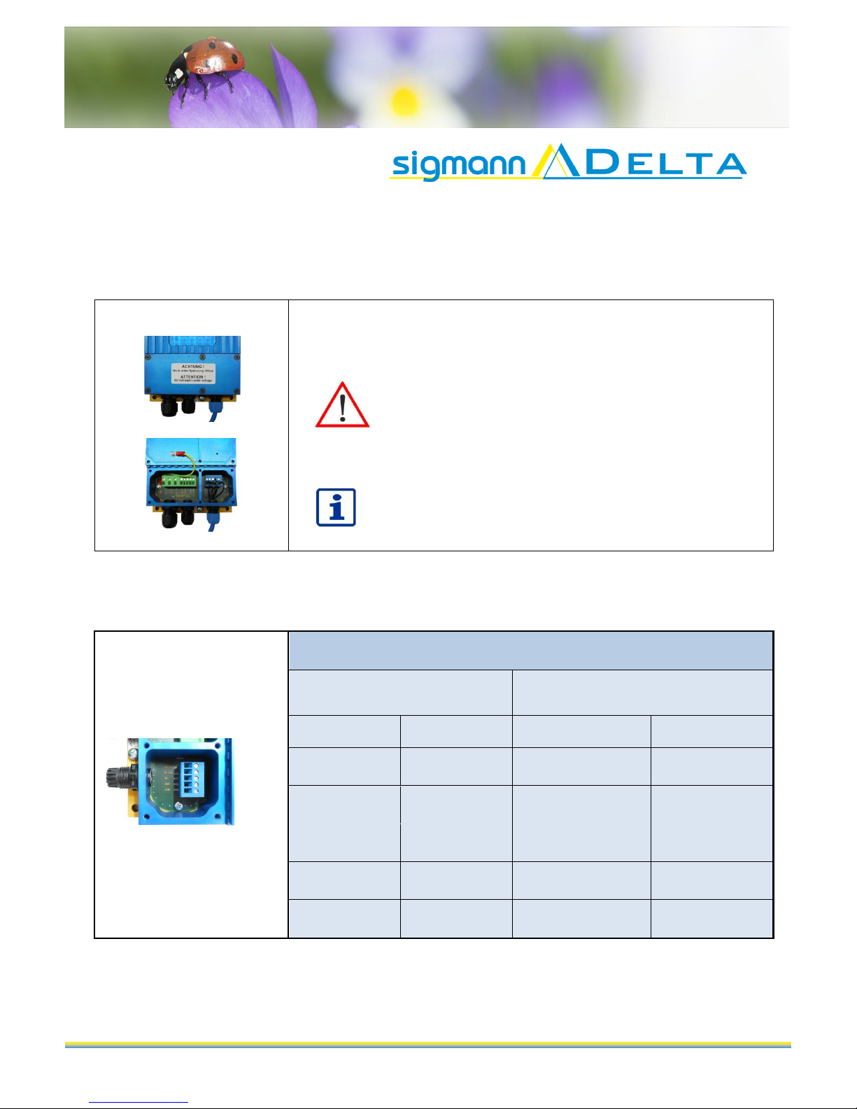
5.4 Pin assignment in the Ex-i connection box of the SDVM125ex
with USB interface (SD.211.X1X1.00)
The terminal assignment is located underneath the removable cover at the front of the
power supply.
Caution!
Do not open enclosure in hazardous area!
Before operating the device in a hazardous area you have to ensure that the enclosure
has been closed fully and all screws have been tightened.
Any changes to the wiring may only be carried out by trained staff.
Pin assignment in the Ex-i connection box USB
Power supply Type: SD.211.X1X1.00
Prepared
Connection coupling
Connection box
Pin
Wire
Definition
Number
3
3
D+
X9
2
4
D-
X10
PE
X11
4
2
GND
X12
1
1
+UB
X13

SDVM125ex_BA_en_003 17
6.1 EC type examination certificate: SDVM125ex
6Attachment

SDVM125ex_BA_en_003 18
Table of contents
Popular Power Supply manuals by other brands


TDK-Lambda
TDK-Lambda HWS 1000/ME Series instruction manual

StarTech.com
StarTech.com ATXPOW350DF Instruction guide

Guntermann & Drunck
Guntermann & Drunck MultiPower-2-RPM installation guide

Bedrock
Bedrock SPS.500 user manual

Whyte
Whyte WPSU-SAP1 instruction manual

Johansson
Johansson 9933 instruction manual


