Bedrock SPS.500 User manual

Revision 7 September 2021
Bedrock OSA
SPS.500
User Manual

Copyright © 2021 Bedrock Automation Platforms, Inc. All rights reserved.
This manual is provided solely for informational purposes in connection with the authorized installation, use, and maintenance
of Bedrock Automation’s products. The information in this manual is subject to change without notice. The most recent
versions of our manuals are posted on our website at https://bedrockautomation.com/support/support-documentation. No
part of this publication may be distributed or transmitted in any form or by any means for charge or for use other than in
connection with the authorized installation, use, and maintenance of Bedrock Automation’s products, without the prior
written permission of Bedrock Automation.
Disclaimer
This manual is provided “as is” without any representations or warranties, express or implied. To the extent allowed by law,
Bedrock Automation makes no, and disclaims any and all, representations or warranties with respect to this manual and the
information and materials provided herein, including without limitation, any implied warranties of non-infringement,
merchantability, fitness or sufficiency for a particular purpose, or arising from the course of dealing, usage, or trade. Although
we use reasonable efforts to include accurate, up-to-date, and comprehensive information, Bedrock Automation does not
warrant the information in this manual is correct, current, or complete. The examples and diagrams in this manual are included
solely for illustrative purposes, and throughout this manual we use notes to make you aware of safety considerations. However,
because of the many variables and requirements associated with any installation, Bedrock Automation cannot assume
responsibility or liability for actual use based on the examples, diagrams, or information included in this manual. Nothing in this
disclaimer excludes or limits any warranty that is unlawful to disclaim, exclude, or limit.
Under no circumstances will Bedrock Automation or its employees, officers, directors, agents, successors, or assigns be liable,
under any contract, tort (including negligence), strict liability or other legal or equitable theory, whether or not foreseeable or
foreseen, for any special, incidental, exemplary, indirect, or consequential damages, including without limitation, any cost of
rework, retesting, procurement of substitute goods, removal and reinstallation of goods, business interruption costs, or lost
revenue, profits, or data, regardless of whether Bedrock Automation has been advised or is aware of the possibility of such
damages or any remedy fails of its essential purpose. Nothing herein will exclude or limit Bedrock Automation’s liability in
respect of any: (1) death or personal injury caused by Bedrock Automation’s negligence; (2) fraud or fraudulent
misrepresentation on the part of Bedrock Automation; or (3) matter which it would be illegal or unlawful for Bedrock
Automation to exclude or limit, or to attempt or purport to exclude or limit, its liability.
By using this manual, you agree these disclaimers, exclusions, and limitations of liability are reasonable. If you do not think they
are reasonable, do not use this manual.
For further information, contact:
Bedrock Automation Platforms, Inc.
171 Forbes Boulevard, Suite 1000
Mansfield, Massachusetts 02048
(781) 821-0280
www.bedrockautomation.com
Trademarks
Bedrock®, Black Fabric®, and OSA® are registered trademarks of Bedrock Automation Platforms, Inc. All other trademarks are the
properties of their respective owners.

Contents
9/3/21 Bedrock SPS.500 User Manual - BRDOC125_007 i
Contents
Safety Warning and Precautions .........................................iii
Warnings ................................................................................................................ iii
Cautions.................................................................................................................. iii
Bedrock SPS.500 Overview .................................................. 1
SPS.500 Installation ............................................................ 7
Important User Information..................................................................................7
Hazardous Location Information .................................................................7
Environment and Enclosure..........................................................................8
Installation Configurations....................................................................................8
Panel Mount Installation........................................................................................9
Pipe Mount Installation........................................................................................10
Installing the SPS.500 ...........................................................................................11
SPS.500 Wiring................................................................. 15
Important User Information................................................................................15
Power and Relay Cables........................................................................................15
Cable Pin Out Information..................................................................................17
Configuration and Status .................................................. 21
Network Setup .......................................................................................................21
Bedrock IDE Device Management .....................................................................21
Displaying SPS.500 Data ............................................................................23
Configuration Data .....................................................................................24
Overcurrent Behavior ..........................................................................27
Diagnostic Data...........................................................................................29
Logging Information....................................................................................31
Log Entry Format.................................................................................32
Logged Events.......................................................................................33
Logged Faults .......................................................................................34
Additional Items Logged by the SPS.500 ............................................35
Storing SPS Logging Information in an ODBC Database..................37
Updating SPS Firmware ..............................................................................37
OPC UA..................................................................................................................37
SPS.500 Status LEDs .............................................................................................39
SPS.500 Specifications.............................................................A-1
SPS.500 Electrical Specifications...........................................................................1

Contents
ii Bedrock SPS.500 User Manual - BRDOC125_007 9/3/21
SPS.500 Environmental Specifications.................................................................2
SPS.500 General Specifications .............................................................................2
Part Numbers ..........................................................................B-1
Certifications, Approvals, and Testing ...................................C-1
CE Testing ................................................................................................................1
IEC Environmental Testing....................................................................................1
Underwriters Laboratories (UL) Safety Compliance..........................................1
FCC Testing..............................................................................................................2
EMP Testing.............................................................................................................2
Achilles Certification..............................................................................................2
Log Index Table...................................................................... D-1
Acronyms.................................................................................E-1
9/3/21 Bedrock SPS.500 User Manual - BRDOC125_007 iii
Safety Warning and Precautions
Observe the following warnings and precautions during installation and use of
the SPS.500.
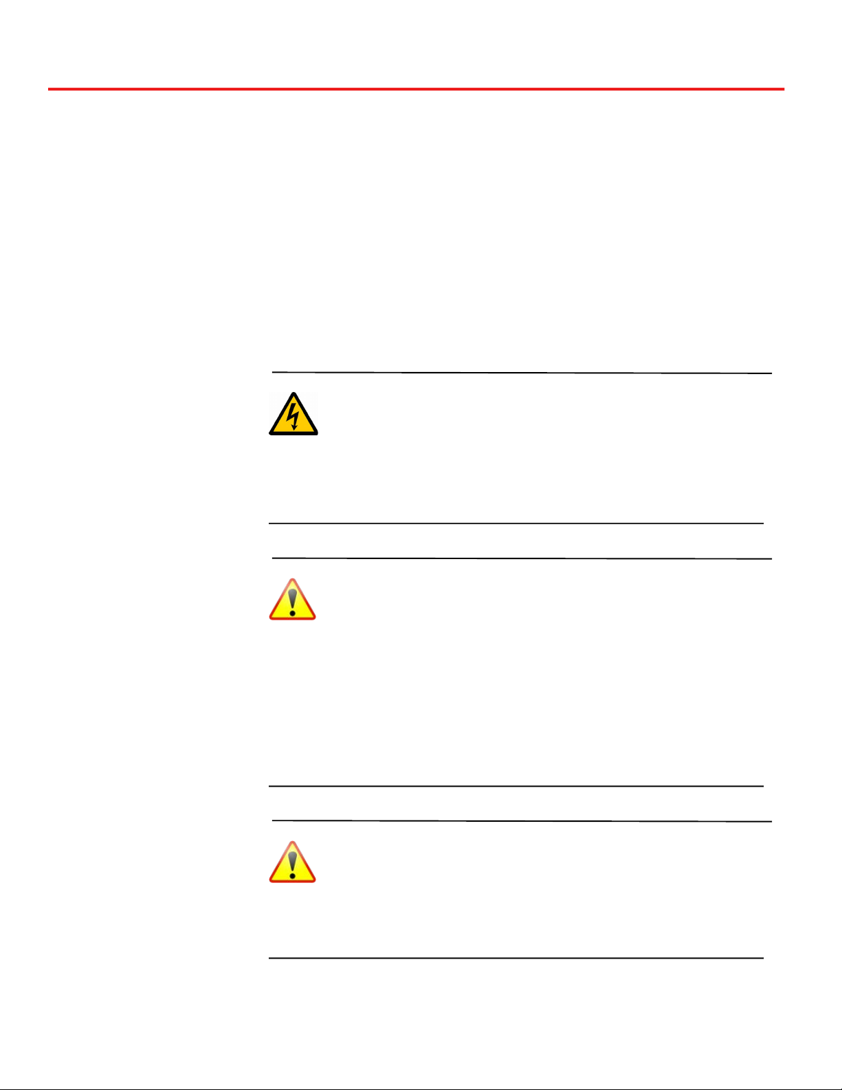
Warnings
WARNING: Dangerous voltages are present within the
power supply. Do not attempt to open the SPS.500 enclosure.
Do not come in contact with the incoming line voltage.
WARNING: Prior to connecting the cables, refer to the
SPS.500 Wiring chapter for important electrical and safety
information.
WARNING: If using revision A of the SPS.500, never use the
Power Out port and “OR”ing output at the same time.
Cautions
CAUTION: Never attempt to open the SPS.500 enclosure.
The enclosure is securely sealed. Opening the enclosure will
void the warranty and cause the SPS.500 to be inoperable.
CAUTION: Always use an appropriate fuse on the Power In
and Power Out connections.
CAUTION: Each contact in the output connectors is rated for
6 amps at 25°C. All wires must be connected to the load in
parallel. Do not use separate wires. Do not connect separate
wires to separate loads. Failure to follow these instructions
will void any warranty.
CAUTION: For both the panel-mount and pipe-mount
configurations, it is required that the SPS.500 universal
mounting bracket is grounded.

Chapter 1
9/3/21 Bedrock SPS.500 User Manual - BRDOC125_007 1
Bedrock SPS.500 Overview
The Bedrock SPS.500 is an Ethernet enabled, 24 V DC power supply designed
for use in a number of applications including IIoT, distributed control systems,
and industrial automation applications. Users of existing applications can retrofit
using the SPS.500 inside or outside enclosures, anywhere in a plant, and in harsh
environments. Product specifications, installation instructions, and operating
information are included in this manual.
The SPS.500 accepts universal AC input voltages. An “OR”ing output is
available for a redundant power supply configuration. The SPS.500 can be
integrated with a Bedrock UPS.500 to provide continuous power to a Bedrock
Control System in the event of a power failure. See the Bedrock UPS.500 User
Manual for more information.
The SPS.500 supports 10/100 Mbit Ethernet IPv4 and IPv6 communication.
Network clock synchronization is provided using the IEEE-1588 Precision Time
Protocol (PTP) for devices that support the protocol.
A real-time clock (RTC) provides up to 21 days of hold up time in the event of a
loss of power to the SPS.500 (product revision B or later).
An OPC UA compliant server provides access to diagnostic and status
information and configuration parameters. OPC UA tags are available using a
single connection to an OPC UA client. Diagnostic, status, and configuration
information is also available using a single connection to the Bedrock IDE.
The SPS.500 can be installed in either panel or pipe mount configuration. The
enclosure is compliant with IP66/67 (dust tight, protection against water jets,
and immersion) and NEMA ratings 4 and 6 (dust tight, water tight, protection
against hose directed water, and immersible).
Bedrock Automation has received several certifications for FCC, CE, IEC, and
EMP testing as well as UL approval for Industrial Control Equipment (UL 508).
See Appendix C, Certifications, Approvals, and Testing for a complete list.
Additional features include:
• tri-colored status LED and network activity LEDs
• two type C relay outputs.
Chapter 1 Bedrock SPS.500 Overview
2 Bedrock SPS.500 User Manual - BRDOC125_007 9/3/21
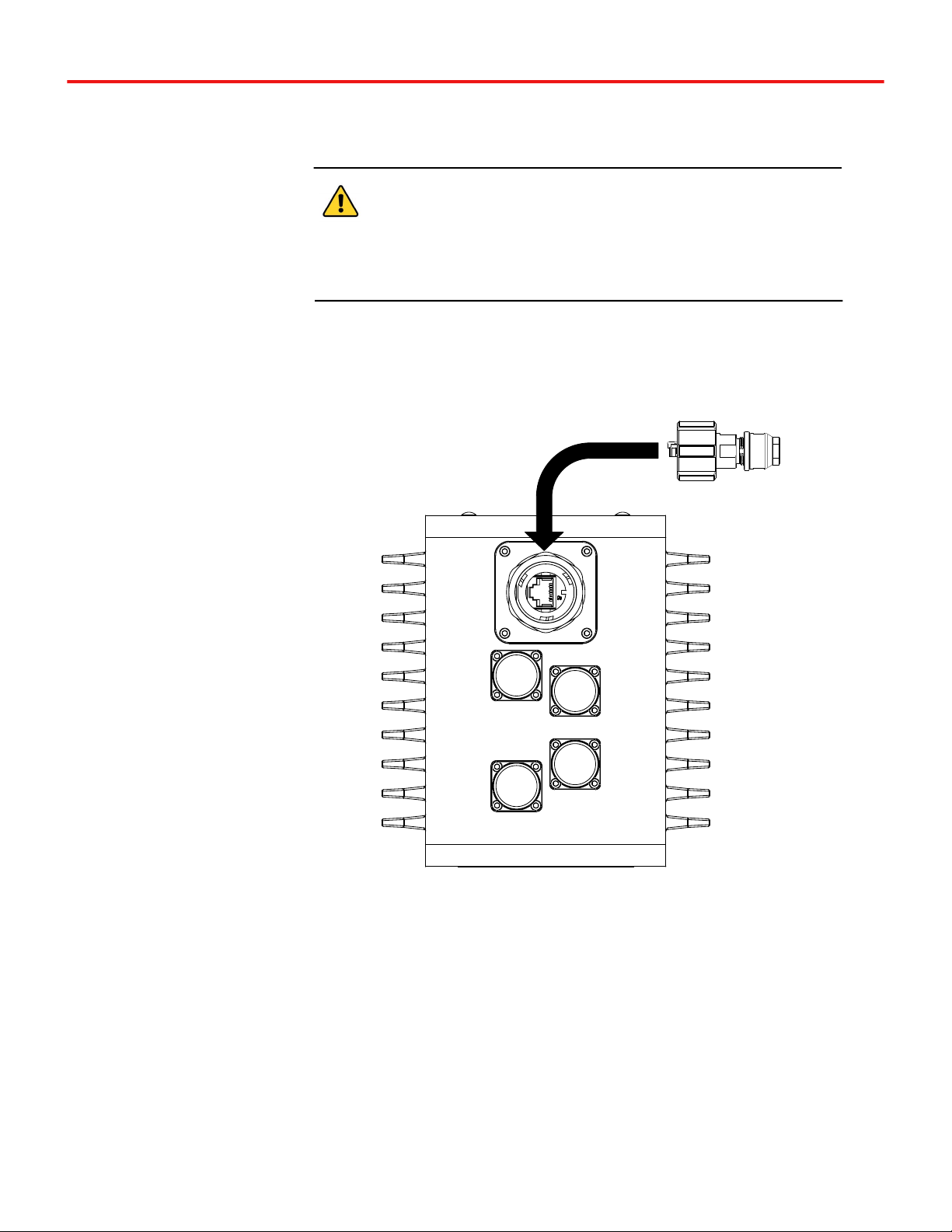
Ports for power cables, communication connections, and the “OR”ing output
are shown in Figure 1-1.
Important
AC Power must be rated for PLTC cable with AWG 14.
DC Power must be rated for PLTC cable with AWG 16.
Relay cabling must be rated for MC, MV, or PLTC with AWG 20.
Figure 1-1 Ports on the SPS.500
Note: Bedrock part no. CI00131 or
TE Connectivity part no. 2ϯϲϮϳϲϬ-2 must
be used for the Ethernet connector
in
order to maintain the IP66/IP67 rating.
Note: A shielded
Ethernet cable is
required.
Relay
Power
In
“OR”ing
Output
Power
Out
Ethernet
Bedrock SPS.500 Overview Chapter 1
9/3/21 Bedrock SPS.500 User Manual - BRDOC125_007 3
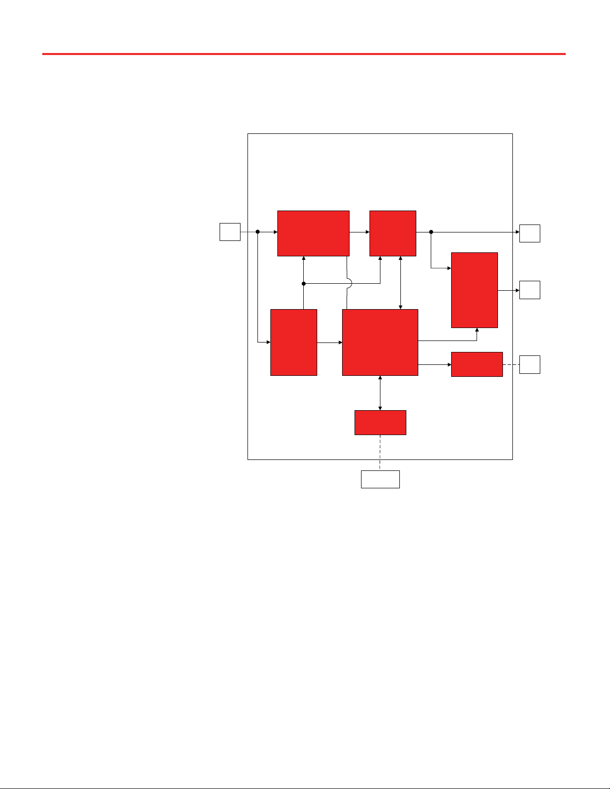
A block diagram for the SPS.500 is shown in Figure 1-2.
Figure 1-2 SPS.500 Block Diagram
Ideal
Diode
Controller
AUX
Supply
PWM
AC
In
OR
Out
PFC
Microcontroller
Relay
DC
Out
Ethernet
Port
Ethernet
Controller
Dual
Relays
DC
Chapter 1 Bedrock SPS.500 Overview
4 Bedrock SPS.500 User Manual - BRDOC125_007 9/3/21
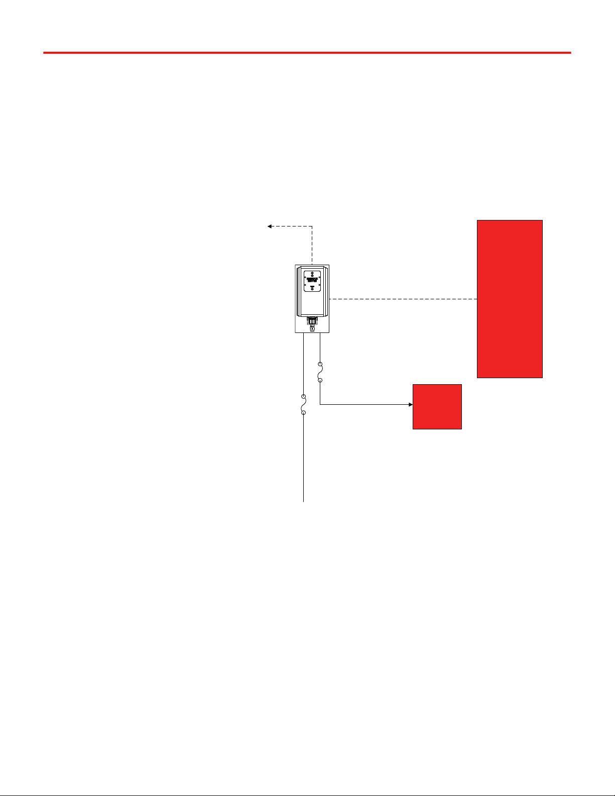
A wiring diagram for a typical non-redundant SPS.500 configuration is shown
in Figure 1-3. Note that the Power Out connector must be used in this
configuration.
Figure 1-3 SPS.500 Wiring Diagram
Two SPS.500 power supplies can be used together in a redundant
configuration. In a redundant configuration, the ORed output controller acts
like an ideal diode. The power supplies do not share the load so that only one
power supply carries the load. The power supply with the highest output
voltage carries the load. The Bedrock IDE or an OPC UA client can determine
which SPS.500 carries the load by checking the amount of current draw of each
supply.
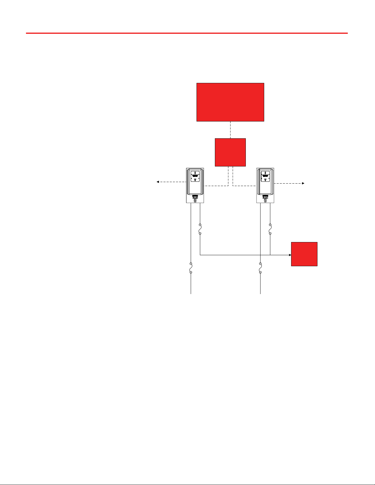
A wiring diagram for a redundant configuration consisting of two SPS.500
power supplies is shown in Figure 1-4. The SPS.500 power supplies can be
connected to a workstation running an OPC UA client by way of an Ethernet
switch. Alternatively, the redundant power supplies can be configured to
Recommended
Fusing / Circuit
Breaker
Power
In
Power
Out
Recommended
Fusing / Circuit
Breaker
Relay
Output
(optional)
Ethernet
AC Mains
Load
One of the
following:
x Workstation
Running
OPC UA
x Bedrock
SIO4.E comm.
module
x UCG.5
x OSA Remote
Bedrock SPS.500 Overview Chapter 1
9/3/21 Bedrock SPS.500 User Manual - BRDOC125_007 5
communicate with a Bedrock SIO4.E communications module or UCG.5
gateway. Note that the “OR”ing Output connector must be used for redundant
configurations.
Figure 1-4 SPS.500 Redundant Configuration
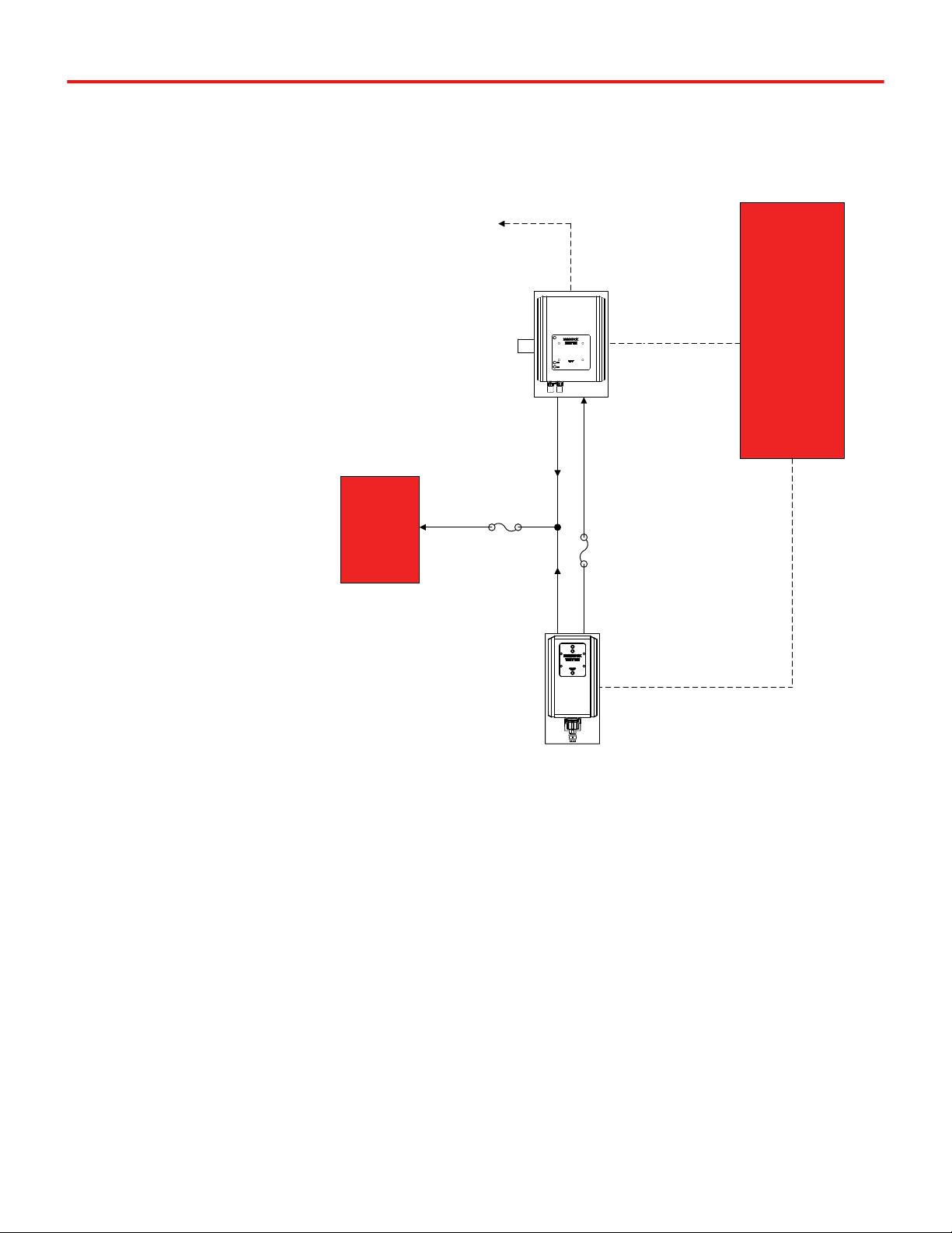
The SPS.500 can be placed in a parallel configuration with an UPS.500. A
parallel configuration will continue to power the load if either the SPS.500
power supply or the UPS.500 is no longer supplying power. The load must be
capable of accepting ORed inputs. Figure 1-5 shows a wiring diagram with the
Recommended
Fusing / Circuit
Breaker
Power
In
“OR”ed
Power Out
Recommended
Fusing / Circuit
Breaker
Relay
Output
(optional)
Ethernet
AC Mains A
Load
Ethernet
Switch
(not needed with
SIO4.E, UCG.5, or
OSA Remote)
Power
In
“OR”ed
Power Out
Recommended
Fusing / Circuit
Breaker
Recommended
Fusing / Circuit
Breaker
AC Mains B
10/100
Ethernet
10/100
Ethernet
Relay
Output
(optional)
Workstation
Running OPC UA
or
SIO4.E, UCG.5, or OSA Remote
Chapter 1 Bedrock SPS.500 Overview
6 Bedrock SPS.500 User Manual - BRDOC125_007 9/3/21
SPS.500 in a parallel configuration with an UPS.500. This is the preferred
configuration for wiring an SPS.500 with an UPS.500.
Figure 1-5 SPS.500 Parallel Wiring Diagram with UPS.500
One of the
following:
x Workstation
Running
OPC UA
x Bedrock
SIO4.E comm.
module
x UCG.5
x OSA Remote
Load
Recommended
Fusing
Power
Out
Power
In
Recommended
Fusing
To Discrete
Inputs for
Alarming
Relay
Output
(optional)
Ethernet
Battery
Enable
Connector
Ethernet
ORed
Output
Power
Out
SPS.500
UPS.500
Chapter 2
9/3/21 Bedrock SPS.500 User Manual - BRDOC125_007 7
SPS.500 Installation
Important User
Information
Read the instructions and follow all warnings and notes prior to beginning
installation.
Complete these tasks before installing and using the SPS.500.
• Verify that you have the components required to install the SPS.500.
• Read and understand the safety and environmental warnings and
considerations explained in the installation instructions.
Hazardous Location
Information
WARNING
EXPLOSION HAZARD - DO NOT DISCONNECT EQUIPMENT WHILE THE CIRCUIT IS
LIVE OR UNLESS THE AREA IS KNOWN TO BE FREE OF IGNITABLE
CONCENTRATIONS.
Important
Note the following with regard to installation of Bedrock SPS.500 equipment in
Class I, Division 2, Groups A, B, C, and D hazardous locations:
THE EQUIPMENT IS SUITABLE FOR USE IN CLASS I, DIVISION 2, GROUPS A,
B, C, AND D HAZARDOUS LOCATIONS, OR NONHAZARDOUS LOCATIONS
WHEN INSTALLED PER CONTROL DOCUMENT BRDOC135_002 (BEDROCK
SPS.500 INSTALLATION GUIDE FOR HAZARDOUS LOCATIONS).
Important
Substitution of components may impair suitability for operation in a Class I,
Division 2, hazardous location.

Chapter 2 SPS.500 Installation
8 Bedrock SPS.500 User Manual - BRDOC125_007 9/3/21
Important
Perform all power wiring in accordance with Class I, Division 2 wiring methods
as defined in Article 501-4 (b) of the National Electrical Code, NFPA 70 (for
installation within the United States) or as specified in Section 18-152 of the
Canadian Electrical Code (for installation in Canada).
Environment and
Enclosure
Important
Subsequent sections of this publication may contain information regarding
specific enclosure type ratings that are required to comply with certain product
safety certifications
In addition to this publication, see the following: NEMA Standard 250 and
IEC 60529, as application for explanation of the degrees of protection provided
by enclosure.
The following information applies when operating the equipment in hazardous
locations:
Products marked “CL I, DIV 2, GP A, B, C, D” are suitable for use in Hazardous
Locations and nonhazardous locations only. Each product is supplied with
markings on the rating nameplate indicating the hazardous location
temperature code. When combining products within a system, the most
adverse temperature code (lowest “T” number) may be used to help determine
the overall temperature code of the system. Combinations of equipment in
your system are subject to investigation by the local Authority Having
Jurisdiction at the time of installation.
Temperature Code T4 has been established for the SPS.500 Power Supply.
The SPS.500 can operate in an ambient temperature range of -25°C to 50°C.
Installation
Configurations
The Bedrock SPS.500 can be installed in one of the following configurations:
• Panel-mount configuration - use four self-tapping screws to secure
the SPS.500 universal mounting bracket to a surface such as a
cabinet or a wall.
• Pipe-mount configuration - hex bolts and nuts secure the SPS.500
universal mounting bracket and bracket straps to a two inch pipe.
SPS.500 Installation Chapter 2
9/3/21 Bedrock SPS.500 User Manual - BRDOC125_007 9
CAUTION: For both the panel-mount and pipe-mount
configurations, it is required that the SPS.500 universal
mounting bracket is grounded.
Panel Mount
Installation
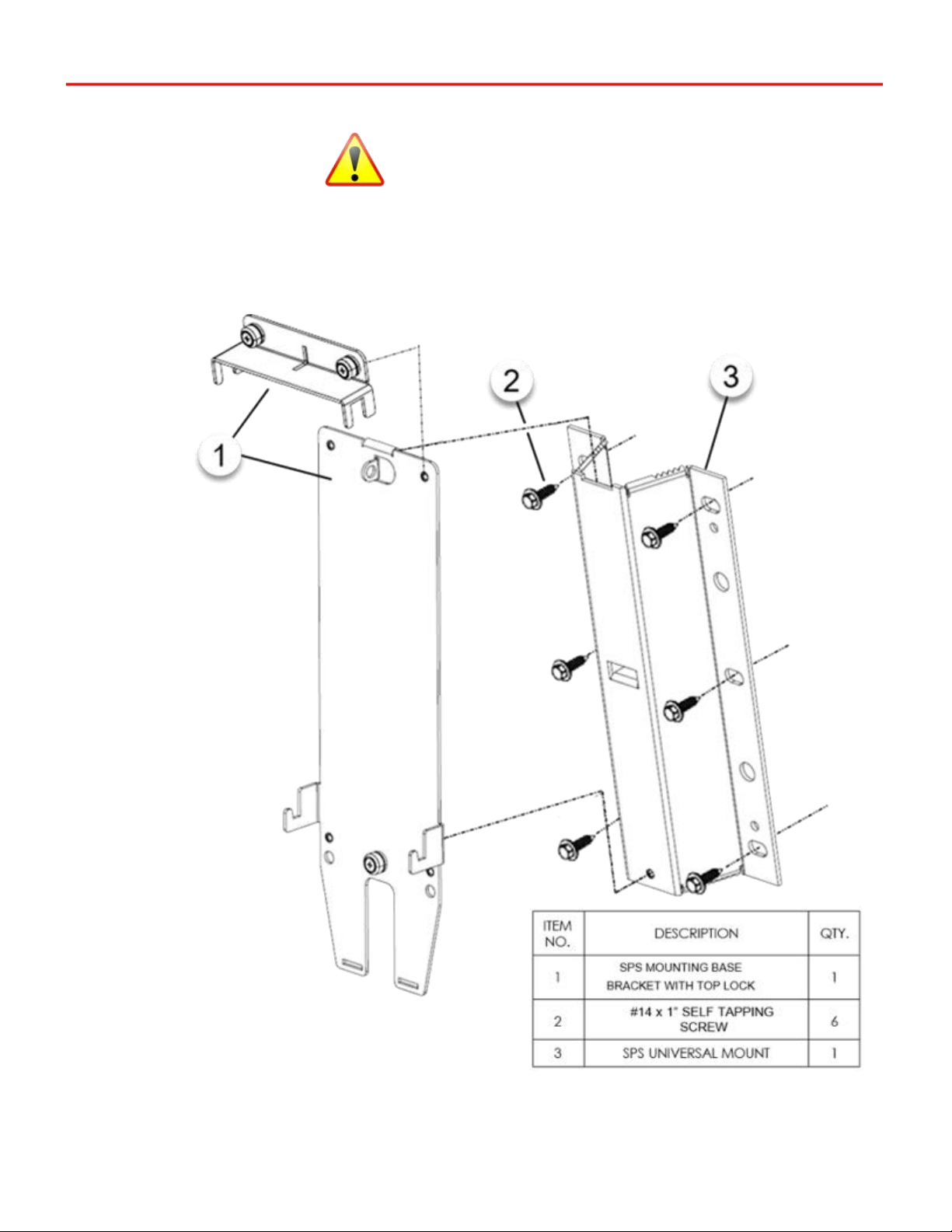
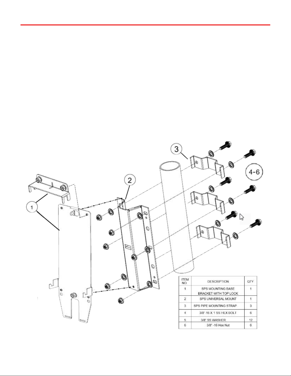
Figure 2-1 shows the bracket assembly for the SPS.500 panel-mount
configuration. Items 1 and 3 are the primary components for the assembly.
Fastener type is dependent on panel mount material. See Table B-1.
Figure 2-1 Bracket Assembly - Panel Mount Configuration
Chapter 2 SPS.500 Installation
10 Bedrock SPS.500 User Manual - BRDOC125_007 9/3/21
After securing the universal mount (Item No. 3) with the appropriate fasteners
(Item No. 2), do the following:
1. Hook the mounting bracket (Item No. 1) onto the SPS universal mount
(Item No. 3).
2. Secure the mounting bracket by tightening the captive screw with a #2
cross-tip screwdriver.
Note: The top lock is used in final assembly when installing the UPS.500
to the mounting bracket.
Pipe Mount
Installation
Figure 2-2 shows the bracket assembly for the SPS.500 pipe-mount
configuration. Use a 3/8 in. socket and open-end wrench to tightening the
universal bracket to the pipe. The steps to secure the mounting base bracket to
the SPS universal mount is described above. See Table B-1 for part numbers.
Figure 2-2 Bracket Assembly - Pipe Mount Configuration
SPS.500 Installation Chapter 2
9/3/21 Bedrock SPS.500 User Manual - BRDOC125_007 11
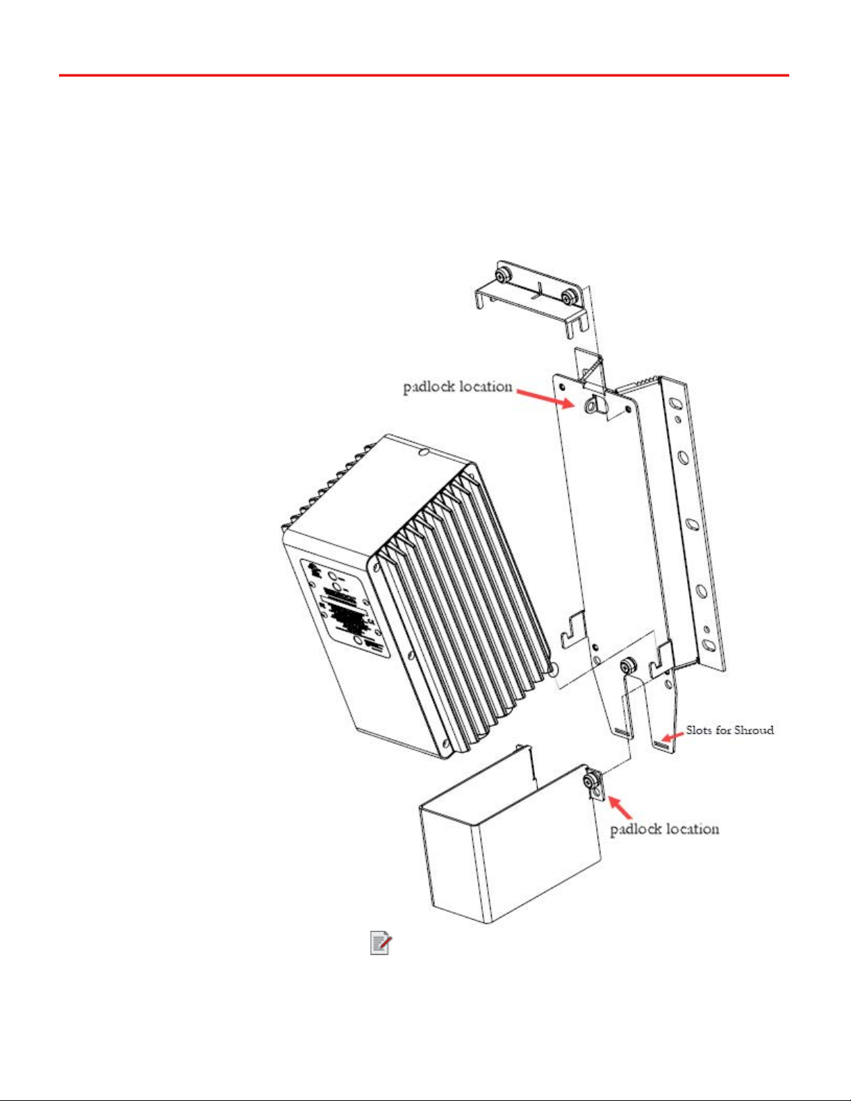
Installing the SPS.500 Figure 2-3 shows the SPS.500 installation to the mounting bracket (no cables
installed). The shroud gets installed after connecting cables. See Table B-1 for
part numbers.
1. Place the SPS.500 into the J-brackets, and then place the top locking
bracket onto the unit.
2. Tightened the top locking bracket’s two captive screws with a #2 cross-
tip screwdriver.
Figure 2-3 SPS.500 Installation to Bracket Hardware
Padlocks are required for hazardous locations.
Chapter 2 SPS.500 Installation
12 Bedrock SPS.500 User Manual - BRDOC125_007 9/3/21
WARNING: Prior to connecting the cables, refer to the SPS.500
Wiring chapter for important electrical and safety information.
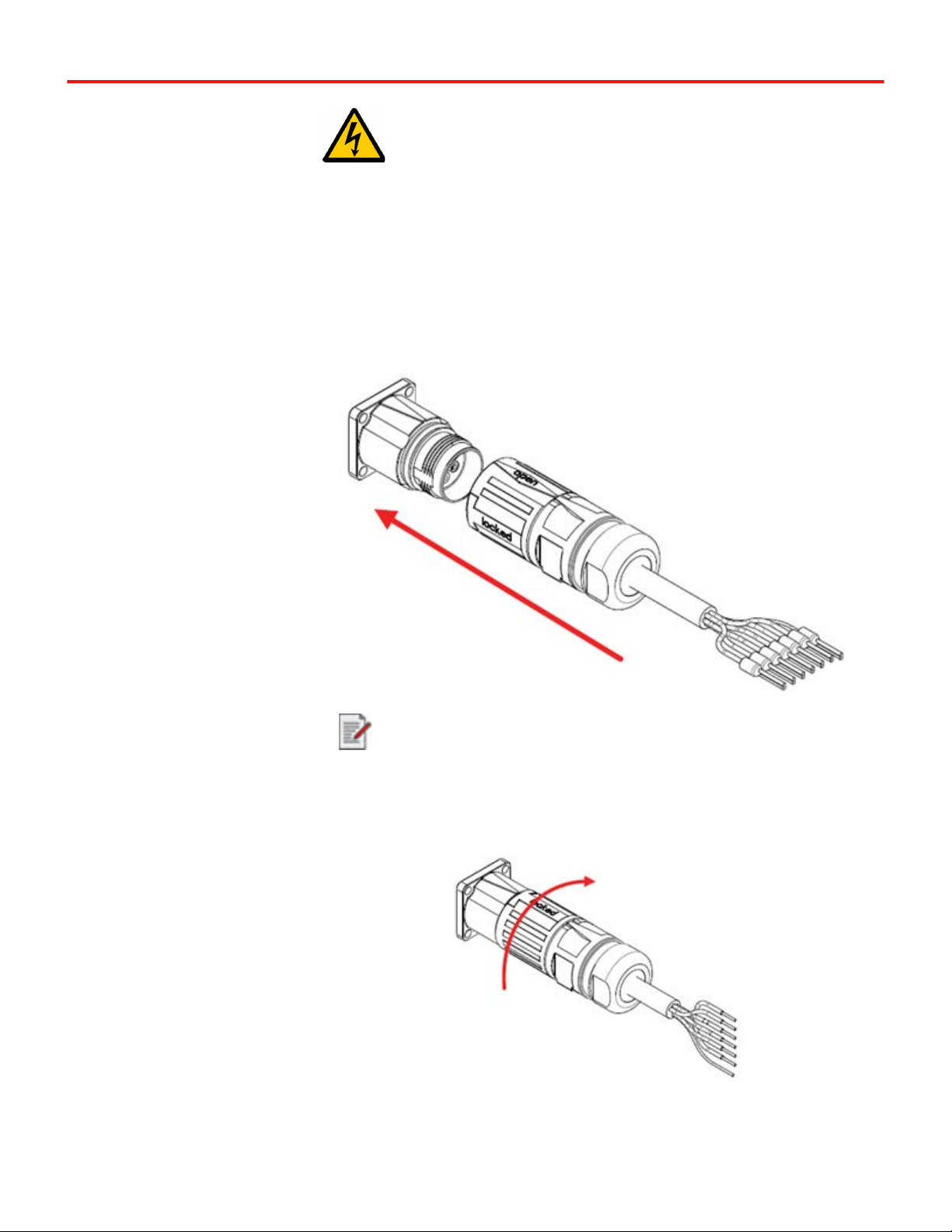
3. Connect the AC Power In cable, Power Out cable (use the “OR”ing
out cable in a redundant configuration), and the Relay cable
(optional) to the SPS.500. Connections are made as follows:
a. Align the Open arrow with the arrow on the mating connector and
then press together as shown in Figure 2-4.
Figure 2-4 Connector Alignment
b. Rotate 1/4 turn clockwise to the locked position.
Figure 2-5 Locked Connector
Although a power cable is shown, the connection method applies to
all connections except for the Ethernet cable.

SPS.500 Installation Chapter 2
9/3/21 Bedrock SPS.500 User Manual - BRDOC125_007 13
Figure 2-6 shows the SPS.500 with connectors locked and Ethernet cable
connected.
Figure 2-6 SPS.500 with Installed connectors
Important Notes:
AC Power must be rated for PLTC cable with AWG 14.
DC Power must be rated for PLTC cable with AWG 16.
Relay cabling must be rated for MC, MV, or PLTC with AWG 20.

Chapter 2 SPS.500 Installation
14 Bedrock SPS.500 User Manual - BRDOC125_007 9/3/21
The shroud secured over the connectors prevents the SPS.500
cables from disconnecting The shroud is required in Class I,
Division 2 hazardous locations. See the Bedrock SPS.500
Installation Guide for Hazardous Locations for additional
information.
After, the connectors have been attached and locked, place the shroud over the
connectors. Do the following:
1. Insert the bottom of the shroud into the two mounting bracket slots (as
shown in Figure 2-3).
2. Tighten the shroud’s two captive screws with a #2 cross-tip screwdriver.
Figure 2-7 Shroud in Closed Position Showing Padlock Locations
Padlocks are required for hazardous locations

Chapter 3
9/3/21 Bedrock SPS.500 User Manual - BRDOC125_007 15
SPS.500 Wiring
Important User
Information
Be sure to observe the following when working with the SPS.500.
WARNING: Dangerous voltages are present within the power
supply. Do not attempt to open the SPS.500 enclosure. Do not
come in contact with the incoming line voltage.
CAUTION: Always use an appropriate fuse on the power in
and power out connections.
CAUTION: Never attempt to open the SPS.500 enclosure. The
enclosure is securely sealed. Opening the enclosure will void
the warranty and cause the SPS.500 to be inoperable.
Power and Relay
Cables
Wire labels for the power in, power out, “OR”ing output, and relay cables for the
SPS.500 are illustrated in Figure 3-1.
WARNING: If using revision A of the SPS.500, never use the
Power Out port and “OR”ing output at the same time.
NOTE: For all cables, connect the drain wire to panel ground.
CAUTION: See the Specifications appendix for relay contact
rating information.
Table of contents


