Sigmar marine TERMOINOX B0 22 UT User manual

BOILER TERMOINOX
B0 20 UT
B0 22 UT
B0 30 UT
B0 40 UT
B0 60 UT
REV 001A
Manuale d’uso BOILER TERMOINOX
User’s Manual TERMOINOX WATER HEATER
Manuel de l’utilisateur CHAUFFE-EAU TERMOINOX
Benutzerhandbuch BOILER TERMOINOX
Manual del usuario CALENTADOR TERMOINOX
Manual de uso AQUECEDOR TERMOINOX
Bruksanvisning VATTENVÄRMARE TERMOINOX
Handleiding BOILER TERMOINOX
IT
GB
FR
DE
ES
PT
SE
NL


BOILER TERMOINOX 20/60 - REV001A
3
INDICE
INDEX
SOMMAIRE
INHALTSANGABE
INDICE
IT
GB
FR
DE
ES
ÍNDICE
INNEHÅLLSFÖRTECKNING
INDEX
PT
SE
NL
Pag. 4 Caratteristiche tecniche
Pag. 5 Installazione
Pag. 6 Schema di collegamento
Pag. 7 Uso - Avvertenze importanti
Pag. 8/9 Manutenzione
Pag. 10 Technical data
Pag. 11 Installation
Pag. 12 Connection diagram
Pag. 13 Usage
Pag. 14/15 Maintenance
Pag. 16 Caractéristiques techniques
Pag. 17 Installation
Pag. 18 Schema de cablage
Pag. 19 Utilisation
Pag. 20/21 Entretien
Seite 22 Technische Eigenschaften
Seite 23 Montage
Seite 24 Anschlussplan
Seite 25 Gebrauch
Seite 26/27 Wartung
Pág. 28 Características técnicas
Pág. 29 Instalación
Pág. 30 Esquema de montage
Pág. 31 Uso
Pág. 32/33 Mantenimiento
Pág. 34 Características técnicas
Pág. 35 Instalação
Pág. 36 Esquema de conexão
Pág. 37 Uso
Pág. 38/39 Manutenção
Pag. 46 Technische eigenschappen
Pag. 47 Installatie
Pag. 48 Aansluitingsschema
Pag. 49 Gebruik
Pag. 50/51 Onderhoud
Sid. 40 Tekniska egenskaper
Sid. 41 Installation
Sid. 42 Kopplingsschema
Sid. 43 Användning
Sid. 44/45 Underhållsarbete

4
CARATTERISTICHE TECNICHE
BOILER TERMOINOX 20/60 - REV001A
IT
COME SI LEGGE IL MODELLO DEL BOILER:
a b c d e
a
a
a
a
a
ESEMPIO: B020UT08
B0 20 UT 08 -
Nome del prodotto:
[ B0 ] = Boiler Sigmar
Capacità del
serbatoio:
[ 20 ] = 20 litri
[ 22 ] = 22 litri
[ 30 ] = 30 litri
[ 40 ] = 40 litri
[ 60 ] = 60 litri
Potenza della
resistenza elettrica:
[ 08 ] = 800 W
[ 01 ] = 1200 W
Modello:
[ UT ] = Termoinox
a
b c d
Tensione resistenza
elettrica (se installata):
[ - ] = 220 Vac
[ L ] = 110 vac
e
(1)
1 Bar = 100 kPa
(2)
Peso a vuoto
B020UT B022UT B030UT B040UT B060UT
20 L 22 L 30 L 40 L 60 L
(5.3 gal) (5.8 gal) (7.9 gal) (10.6 gal) (15.8 gal)
Acciaio inox
Poliuretano espanso rigido a cellule chiuse
500 kPa
(1)
500 kPa
(1)
220 Vac ± 10% (110 Vac ± 10%)
800W (modello 08) - 1200 W (modello 01)
1/2”
7 kg 6,3 kg 8,2 kg 9,2 kg 11,6 kg
(15.4 lb) (13.9 lb) (18.0 lb) (20.3 lb) (25.6 lb)
MODELLO
CAPACITÀ SERBATOIO
Unità di misura:L(U.S gal) = Litro (USA gallone)
Materiale serbatoio
Isolante termico
Materiale rivestimento esterno
Pressione serbatoio durante collaudo
Pressione massima d’esercizio
Tensione elemento riscaldante
Potenza elemento riscaldante
Diametro raccordi
Peso
(2)
Quick®si riserva il diritto di apportare modifiche alle caratteristiche tecniche dell'apparecchio e al contenuto di questo manuale senza alcun preavviso.
In caso di discordanze o eventuali errori tra il testo tradotto e quello originario in italiano, fare riferimento al testo italiano o inglese.
Questo dispositivo è stato progettato e realizzato per essere utilizzato su imbarcazioni da diporto. Non è consentito un utilizzo differente senza autorizza-
zione scritta da parte della società Quick®.
F

5
INSTALLAZIONE
BOILER TERMOINOX 20/60 - REV001A
IT
BOILER NAUTICO
La lunga esperienza maturata nel settore della nautica ci ha permesso di sviluppare una serie di boiler con
caratteristiche innovative rispetto allo standard di mercato.
I vantaggi che i boiler nautici Sigmar Marine offrono sono:
• elevata qualità dei materiali che garantiscono lunga durata e resistenza.
• Scambiatore di calore dotato di notevole superficie di scambio.
• Possibilità di produrre acqua calda anche con la resistenza elettrica, completa di termostato di sicurez-
za regolabile (nei modelli provvisti).
• Valvola di sicurezza e di ritegno che permette di scaricare l’acqua del boiler in caso di inutilizzo.
• Pratica installazione su piano.
BEFORE USING THE WATER HEATER READ CAREFULLY THIS INSTRUCTION MANUAL.
IF IN DOUBT, PLEASE CONTACT THE NEAREST SIGMAR MARINE.
ATTENZIONE: utilizzare il boiler solo per le applicazioni descritte in questo manuale. Non utilizzare
questo apparecchio per altri tipi di operazioni. Quick non si assume alcuna responsabilità per i dan-
ni diretti o indiretti causati da un uso improprio dell’apparecchio.
LA CONFEZIONE CONTIENE: boiler - manuale d’uso - condizioni di garanzia.
AMBIENTE DI INSTALLAZIONE
Il boiler deve essere montato in un luogo asciutto e ben ventilato. Questa precauzione si rende necessaria,
anche se il boiler è costruito con materiali resistenti all’ambiente marino, vista la presenza di dispositivi
elettrici (nei modelli provvisti). Inoltre l’installazione in ambienti non aerati potrebbe causare fenomeni di
condensa; la condensa può essere scambiata per una perdita che in realtà non esiste.
INSTALLAZIONE
• Applicare le fasce (10) al serbatoio utilizzando le viterie fornite a corredo (12, 13, 14, 15).
• Fissare il boiler su piano, parete o piano inclinato come indicato in figura 1 utilizzando supporti idonei al
peso del boiler ed al tipo di piano o parete a disposizione per l’installazione.
ATTENZIONE: il peso del boiler indicato nelle caratteristiche tecniche è a vuoto. Per il peso a pieno
carico aggiungere al peso a vuoto il peso della massa d’acqua contenuta (1 litro d’acqua corrispon-
de circa ad 1 Kg. / 2,2 lb).
• Effettuare gli allacciamenti idraulici relativi all’entrata ed uscita dell’acqua sanitaria ed al circuito di
raffreddamento del motore allo scambiatore di calore come da figura 2. Rendere più corto possibile il
collegamento fra il circuito di raffreddamento del motore e lo scambiatore del boiler.
ATTENZIONE: il tubo di scarico della sovrapressioni deve essere posizionato in pendenza contiu-
na verso il basso ed in luogo protetto dalla formazione di ghiaccio.
ATTENZIONE: l’acqua può gocciolare dal tubo di scarico del dispositivo contro le sovrapressioni e
questo tubo deve essere lasciato aperto all’atmosfera.

6
BOILER TERMOINOX 20/60 - REV001A
IT
6
FIG.3
FIG.1
FIG.2
LIQUIDO
RAFFREDDAMENTO
MOTORE
USCITA ACQUA
SANITARIA CALDA
INGRESSO ACQUA
SANITARIA FREDDA
SERBATOIO ACQUA
SANITARIA
AUTOCLAVE ACQUA FREDDA
ACQUA CALDA
VASO AD ESPANSIONE
NEUTRO RETE AC FASE RETE AC
PULSANTE
RIARMO
MANOPOLA
REGOLAZIONE
TEMPERATURA
TERRA
SCHEMA DI COLLEGAMENTO

7
BOILER TERMOINOX 20/60 - REV001A
IT
7
ATTENZIONE: seguire le istruzioni del fabbricante del motore per il prelievo del liquido di raffredda-
mento da inviare allo scambiatore del boiler.
• Aprire i rubinetti dell’acqua calda dei lavandini e avviare l’autoclave. In questo modo viene fatta defluire
l’aria presente all’interno del boiler e nelle tubature. Chiudere i rubinetti non appena comincia ad uscire
solamente acqua.
• Verificare che non vi siano perdite dai raccordi.
ALIMENTAZIONE ELETTRICA DELL’APPARECCHIO
L’apparecchio non è dotato del cavo di alimentazione per la rete AC. Per i collegamenti alla rete AC vedere
figura 3. Prima di alimentare il boiler accertarsi che la sua tensione di funzionamento corrisponda a quella
fornita dalla rete AC.
Nell’impianto elettrico deve essere installato un interruttore bipolare per accendere e spegnere l’apparec-
chio ed un fusibile adeguato all’assorbimento. L’isolamento fra i contatti delle connessioni sulla rete AC
deve essere come minimo di 3 mm. Le connessioni alla rete AC devono essere realizzate in accordo alle
norme nazionali degli impianti elettrici.
ATTENZIONE: prima di effettuare il collegamento accertarsi che non sia presente l’alimentazione
sui cavi.
ATTENZIONE: nel caso in cui il cavo di alimentazione sia danneggiato, farlo sostituire da un centro
assistenza Sigmar Marine. Per evitare incidenti l’apparecchio deve essere aperto solo da personale
autorizzato. L’apertura dell’apparecchio da parte di personale non autorizzato fa decadere la garanzia.
ATTENZIONE: non accendere mai la resistenza elettrica se il boiler non è pieno d’acqua pena un
danneggiamento irreversibile dell’elemento riscaldante.
REGOLAZIONE DEL TERMOSTATO
Il valore di temperatura impostato sul termostato dalla fabbrica è di 70°C. Se si desidera variare questo
valore seguire la procedura riportata di seguito:
• interrompere l’alimentazione elettrica.
• Smontare il coperchio di protezione (8) per accedere al termostato.
• Tramite un cacciavite agire sulla manopola del termostato (figura 3) ed impostare il valore di temperatu-
ra desiderato.
• Montare il coperchio di protezione (8).
• Ripristinare l’alimentazione elettrica.
Il termostato regola la temperatura dell’acqua esclusivamente nel funzionamento con resistenza
elettrica.
F
USO - AVVERTENZE IMPORTANTI

8
BOILER TERMOINOX 20/60 - REV001A
IT
8
10
11
15
14
13
13
12
14
15
8
9
9
7
6
5
2
2
3
4
1
9
10
11
15
14
13
13
12
14
15
MANUTENZIONE

9
BOILER TERMOINOX 20/60 - REV001A
IT
9
ATTENZIONE: i boiler Sigmar Marine sono dotati
di bi-termostato a riarmo manuale che interrompe
l’alimentazione elettrica in caso di eccessiva tem-
peratura dell’acqua.
Nel caso in cui si verifichi questa condizione pro-
cedere come riportato di seguito:
• interrompere l’alimentazione elettrica.
• Smontare il coperchio resistenza (8) per accedere al
termostato (7).
• Premere in pulsante di riarmo del bi-termostato (fig. 3).
• Montare il coperchio resistenza (8).
• Ripristinare l’alimentazione elettrica.
ATTENZIONE: nel caso in cui la sicurezza di so-
vra temperatura intervenga in maniera ripetuta
durante l’utilizzo del boiler contattare un centro
assistenza Sigmar Marine.
MANUTENZIONE
Durante la stagione fredda, nel caso in cui il boiler
non sia utilizzato, è consigliabile vuotare il boiler
agendo sulla leva della valvola (4). Questo per evi-
tare danni prodotti dal gelo.
Il dispositivo contro le sovrapressioni deve essere fatto
funzionare regolarmente per rimuovere i depositi di cal-
care e per verificare che non sia bloccato.
Verificare periodicamente la tenuta dei raccordi del-
l’impianto idraulico; controllare la chiusura delle viterie
di fissaggio e sostituire nel caso in cui siano usurate o
corrose.
Verificare periodicamente l’efficienza dell’impianto elet-
trico.
POS. DENOMINAZIONE CODICE
1 Rosetta plastica rossa PVRPC300R000
2 Rosetta plastica gialla PVRPM300G000
3 Rosetta plastica blu PVRPF300B000
4 Valvola di sicurezza e di ritegno MNVALS120000
5 Guarnizione resistenza PGR031430000
6A Resistenza elettrica
800W 220V EVR08220NSG0
6B Resistenza elettrica
800W 110V EVR08110NSG0
6C Resistenza elettrica
1200W 220V EVR12220NSG0
6D Resistenza elettrica
1200W 110V EVR12110NSG0
7 Bi-termostato EVT101100000
8 Coperchio resistenza PCCBRNP00000
9 Dado M4 Inox MBD04MXEN000
10A Fascia metallica
per 22 Lt SLMMFS67TRX0
10B Fascia metallica
per 20-30-40-60 Lt SLMMFS89TSX0
11 Staffa metallica SLMMSTSP25P0
12 Vite M8 x 20 Inox MBV0820MXE00
13 Vite M8 x 40 Inox MBV0840MXE00
14 Rondella Ø8 MBV08X000000
15 Dado M8 Inox MBD08MXEN000
MANUTENZIONE
F

10
TECHNICAL DATA
BOILER TERMOINOX 20/60 - REV001A
GB
HOW TO IDENTIFY THE WATER HEATER THROUGH THE CODE:
a b c d e
a
a
a
a
a
EXAMPLE: B020UT8
B0 20 UT 08 -
Product name:
[ B0 ] = Water heater
Sigmar
Tank capacity
(liter):
[ 20 ] = 20 liter
[ 22 ] = 22 liter
[ 30 ] = 30 liter
[ 40 ] = 40 liter
[ 60 ] = 60 liter
Power of electric
element:
[ 8 ] = 800 W
[ 1 ] = 1200 W
Model:
[ UT ] = Termoinox
a
b c d
Voltage of electric
element (if installed):
[ - ] = 220 Vac
[ L ] = 110 vac
e
(1)
1 Bar = 100 kPa
(2)
Of empty equipment
B020UT B022UT B030UT B040UT B060UT
20 L 22 L 30 L 40 L 60 L
(5.3 gal) (5.8 gal) (7.9 gal) (10.6 gal) (15.8 gal)
Stainless Steel
Polyurethane foam
Polyurethane foam
500 kPa
(1)
500 kPa
(1)
220 Vac ± 10% (110 Vac ± 10%)
800W (model 08) - 1200 W (model 01)
1/2”
7 kg 6,3 kg 8,2 kg 9,2 kg 11,6 kg
(15.4 lb) (13.9 lb) (18.0 lb) (20.3 lb) (25.6 lb)
MODEL
TANK CAPACITY
Unit of measur: L(U.S gal) = Liter (gallon US)
Tank material
Thermal insulating
External claddind material
Tank pressure during running test
Maximum working pressure
Electric element voltage rating
Electric element power
Outputs diameter
Weight
(2)
Quick®reserves the right to introduce changes to the equipment and the contents of this manual without prior notice.
In case of discordance or errors in translation between the translated version and the original text in the Italian language, reference will be made to the Italian or English text.
This device was designed and constructed for use on recreational crafts. Other forms of use are not permitted without written authorization from the
company Quick®.
F

11
INSTALLATION
BOILER TERMOINOX 20/60 - REV001A
GB
TERMOINOX WATER HEATER
Our long experience operating in the nautical field has given us the means to supply a new series of water
heaters with innovative characteristics compared with other avaible heaters.
The advantages, given by Sigmar Marine nautic boilers, are:
• high quality of materials ensure the product is both reliable and long lasting.
• Heat exchanger with a large exchanging surface.
• Producing hot water also by means of an electric element, which is provided with an adjustable
and safety thermostat.
• Relief/non return valve that allows discharging of water heater in case of disuse.
• The installation is easy and practical on a flat area.
BEFORE USING THE WATER HEATER READ CAREFULLY THIS INSTRUCTION MANUAL.
IF IN DOUBT, PLEASE CONTACT THE NEAREST “SIGMAR MARINE” DEALER.
WARNING: use this water heater in the applications described in this manual. Don’t use the equip-
ment for any other purposes. Quick
®
will not be held responsible for damage to equipment and/or
personal injuries cause by a misusage of the equipment.
PAKAGE CONTAINS: water heater - user’s manual - conditions of warranty.
INSTALLATION SITE
The water heater has to be placed in a dry and well-ventilated location. This precaution is required, even
though water heaters are made of sea environment resistant materials, since electrical systems are
present (in model provided with). Also if they are installed in environments that are not ventilated conden-
sation could occur. Condensation could be mistaken for a leak.
SET UP
• Put mounting (10) on the tank using studs and nuts provided (12, 13, 14, 15).
• Fix water heater on flat or inclined plane or wall, as shown in fig. 1, using proper mountings for the
weight of the water heater and for the type of installation site in the boat.
WARNING: the weight of water heater/unit in technical data refers to the empty unit. In order
to have the gross weight add to the empty weight, the water amount. (1 liter of water will almost
weigh 1 Kg. / 2,2 lb).
• Make hydraulic connections, relating to the input and output of tap water and from the engine
cooling to the heat exchanger, as shown in fig. 2. Make the connections as short as possible
between engine cooling system and heat exchanger.
WARNING: the overpressure release pipe must be positioned sloping evenly downwards in a loca-
tion protected from the formation of ice.
WARNING: water might drip from the overpressure release pipe of the device, and this pipe must
be left open to the atmosphere.

12
BOILER TERMOINOX 20/60 - REV001A
GB
FIG.3
FIG.1
FIG.2
ENGINE
COOLING LIQUID
HOT TAP
WATER OUTPUT
COLD TAP
WATER INPUT
TAP WATER TANK
AUTOCLAVE COLD WATER
HOT WATER
EXPANSION TANK
NEUTRAL AC
NETWORK FASE RETE AC
RESET
BUTTON
THERMOSTAT
KNOB
EARTH
CONNECTION DIAGRAM

13
BOILER TERMOINOX 20/60 - REV001A
GB
WARNING: follow the instructions of the boat engine manufacturer on how to connect engine cool-
ing liquid to the heat exchanger.
• Open up hot water taps of washbasins and start the water pump. This allows water to fill water
heater and force air out of the water heater and pipes. Close taps as soon as air free water comes
out of the taps.
• Check that there are no leaks on pipe joints.
UNIT POWER SUPPLY
The unit is provided with power supply cable for AC current. For the connection see fig. 3. Make sure the
water heater working voltage is the same as that provided from AC network.
A double pole switch has to be included on the electric installation in order to turn on and off the unit, and
a fuse of suitable rating. The insulation between connection contacts of the AC network must be at least
3 mm. The connections to AC network must be done following the National Specifications on electrical
installations.
WARNING: make sure there is no power into the cable before making connection.
WARNING: in case the power supply cable is damaged, ensure it is replaced by a Sigmar Marine
service center. In order to avoid accidents, the equipment has to be opened by authorized person-
nel only. If opened by an unauthorized person, the warranty is considered not to be valid.
WARNING: don’t operate the electric element if the tank is not filled with water. It may cause a
permanent damage to the electric element.
THERMOSTAT ADJUSTING
The standard temperature value of the thermostat is 70°C.If you wish to change it, follow the instructions
below:
• shut down power supply.
• Remove the protection cover (8) in order to reach the thermostat.
• Adjust the thermostat knob with a screwdriver (fig. 3) and turn it to the required temperature.
• Replace the protection cover (8).
• Switch on power supply.
The thermostat sets the water temperature only on the electric element function.
F
USAGE - WARNING

14
BOILER TERMOINOX 20/60 - REV001A
GB
10
11
15
14
13
13
12
14
15
8
9
9
7
6
5
2
2
3
4
1
9
10
11
15
14
13
13
12
14
15
MAINTENANCE

15
BOILER TERMOINOX 20/60 - REV001A
GB
WARNING: Sigmar Marine nautic water heaters
are provided with a double thermostat with man-
ual reset that shuts down power supply in case of
an excessive water temperature.
If it happens, follow the instructions below:
• shut down power supply.
• Remove the protection cover (8) in order to reach
the thermostat (7).
• Push on the reset button on the double thermostat
(fig. 3).
• Replace on the protection cover (8).
• Switch on power supply.
WARNING: if the high temperature safety works
repeatedly, call Sigmar Marine service center.
MAINTENANCE
During wintertime, when the water heater is not
in use it should be drained using the lever of the
valve (4). This is to avoid serious damage caused
by freezing.
The overpressure release device must be activated regu-
larly to remove calcium deposits and to check that it is
not blocked.
Periodically check the joints of the water pipe instal-
lation; check the tightness of the securing screws and
replace them in case they are worn or corroded.
Also periodically check the safety of the electrical instal-
lation.
POS. DESCRIPTION CODE
1 Red plastic washer PVRPC300R000
2 Yellow plastic washer PVRPM300G000
3 Blue plastic washer PVRPF300B000
4 Relief/non return valve MNVALS120000
5 Element gasket PGR031430000
6A Electric element
800W 220V EVR08220NSG0
6B Electric element
800W 110V EVR08110NSG0
6C Electric element
1200W 220V EVR12220NSG0
6D Electric element
1200W 110V EVR12110NSG0
7 Bi-Thermostat EVT101100000
8 Boiler resistor cover PCCBRNP00000
9 Nut M4 stainless steel MBD04MXEN000
10A Tank mounting
22 Lt SLMMFS67TRX0
10B Tank mounting
20-30-40-60 Lt SLMMFS89TSX0
11 Metal bracket SLMMSTSP25P0
12 Screw M8 x 20 stainless steel MBV0820MXE00
13 Screw M8 x 40 stainless steel MBV0840MXE00
14 Washer Ø8 MBV08X000000
15 Nut M8 stainless steel MBD08MXEN000
MAINTENANCE
F

16
CARACTERISTIQUES TECHNIQUES
BOILER TERMOINOX 20/60 - REV001A
FR
COMMENT LIRE LE CODE DE CHAUFFE-EAU:
a b c d e
a
a
a
a
a
EXAMPLE: B020UT8
B0 20 UT 08 -
Nom du produit:
[ B0 ] = Chaffe-eau
Sigmar
Capacité du
réservoir en litres:
[ 20 ] = 20 litres
[ 22 ] = 22 litres
[ 30 ] = 30 litres
[ 40 ] = 40 litres
[ 60 ] = 60 litres
Puissance de la
résistance électrique:
[ 8 ] = 800 W
[ 1 ] = 1200 W
Modèle:
[ UT ] = Termoinox
a
b c d
Tension de la résistance
électrique (si installée):
[ - ] = 220 Vac
[ L ] = 110 vac
e
(1)
1 Bar = 100 kPa
(2)
Appareil à vide
B020UT B022UT B030UT B040UT B060UT
20 L 22 L 30 L 40 L 60 L
(5.3 gal) (5.8 gal) (7.9 gal) (10.6 gal) (15.8 gal)
Acier inox
Polyuréthane expansé rigide à cellules fermées
500 kPa
(1)
500 kPa
(1)
220 Vac ± 10% (110 Vac ± 10%)
800W (modèle 08) - 1200 W (modèle 01)
1/2”
7 kg 6,3 kg 8,2 kg 9,2 kg 11,6 kg
(15.4 lb) (13.9 lb) (18.0 lb) (20.3 lb) (25.6 lb)
MODÈLE
CAPACITÉ DU RÉSERVOIR
Unité de measure: L(U.S gal) = Litre (U.S gallon)
Matériau du réservoir
Protection interne
Revêtement externe
Pression du réservoir durante les essais
Pression max. de travail
Tension de l’élément chauffant
Puissance de l’élément chauffant
Diamétre du raccord
Poids
(2)
La société Quick®se réserve le droit d'apporter les modifications nécessaires aux caractéristiques techniques de l'appareil et au contenu de ce livret sans avis préalable.
En cas de discordances ou d’erreurs éventuelles entre la traduction et le texte original en italien, se référer au texte italien ou anglais.
Ce dispositif a été conçu et réalisé pour être utilisé sur des bateaux de plaisance. Tout autre emploi est interdit sans autorisation écrite de la société Quick®.
F

17
INSTALLATION
BOILER TERMOINOX 20/60 - REV001A
FR
CHAUFFE-EAU TERMOINOX
Notre longue expérience du secteur de la navigation nous a permis de développer une série de chauffe-eau
avec des caractéristiques d'avant-garde par rapport aux articles standards que l'on trouve sur le marché.
Les avantages que les chauffe-eau nautiques Sigmar Marine offrent sont les suivants:
• qualité élevée des matériaux garantissant longue durée et résistance.
• Echangeur de chaleur équipé d'une grande surface d'échange.
• Possibilité de produire de l'eau chaude même avec la résistance électrique, complète de thermo-
stat de sécurité réglable (dans les modèles équipés).
• Clapet de sûreté et de retenue permettant de faire s'écouler l'eau du chauffe-eau en cas d'inutilisation.
• Installation pratique à plat.
AVANT DE SE SERVIR DU CHAUFFE-EAU, LIRE ATTENTIVEMENT CE MODE D'EMPLOI.
EN CAS DE DOUTES, S'ADRESSER AU REVENDEUR SIGMAR MARINE.
ATTENTION: ne se servir du chauffe-eau que pour les applications décrites dans ce mode d'emploi.
Ne pas se servir de cet appareil pour d'autres types d'opérations. Quick
®
ne se rend pas responsable
des dommages directs ou indirects causés par un mauvais emploi de l'appareil.
L'EMBALLAGE COMPREND: chauffe-eau - manuel de l’utilisateur - conditions de garantie.
LIEU D'INSTALLATION
Le chauffe-eau doit être installé dans un endroit sec et bien aéré. Il est nécessaire de prendre cette pré-
caution même si le chauffe-eau est construit avec des matériaux résistant à l'habitat marin vu la présence
de dispositifs électriques (dans les modèles équipés).
Installer le chauffe-eau dans un endroit qui n'est pas aéré pourrait causer des phénomènes de condensa-
tion; l'eau de condensation, alors, peut être prise pour une fuite qui, en réalité, n'existe pas.
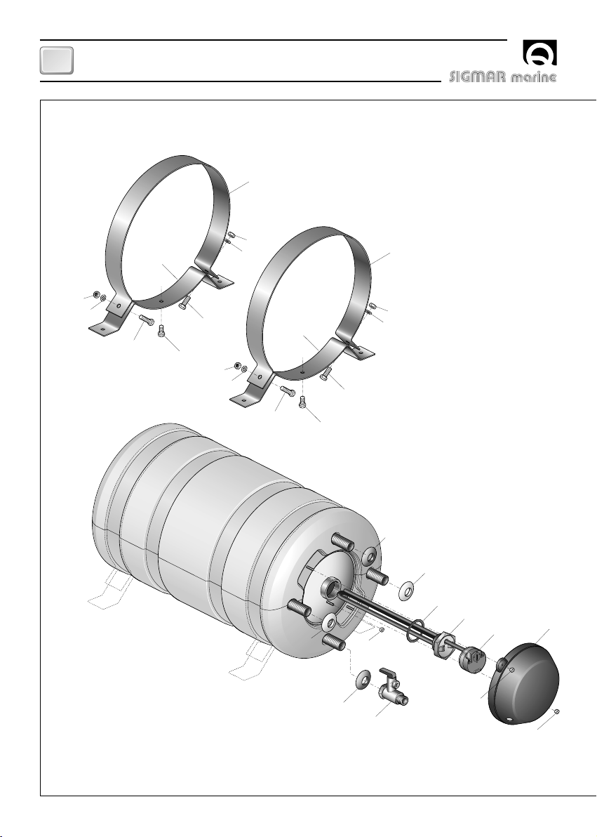
INSTALLATION
• Appliquer les bandes (10) au réservoir en se servant des vis et boulons fournis (12, 13, 14, 15).
• Fixer le chauffe-eau à plat,contre une paroi ou sur une surface inclinée comme indiqué dans la figure 1
à l’aide de supports appropriés au poids du chauffe-eau et au type de surface ou de paroi à disposition
pour l’installation.
ATTENTION: le poids du chauffe-eau indiqué dans les caractéristiques techniques est à vide. Pour
le poids du chauffe-eau rempli d'eau, ajouter au poids à vide le poids de la masse d'eau contenue
(1 litre d'eau correspond à 1 Kg. / 2,2 lb).
• Faire les raccords hydrauliques relatifs à l'entrée et à la sortie de l'eau sanitaire et au circuit de re-
froidissement du moteur à l'échangeur de chaleurcomme d'après la figure 2. La connexion entre le
circuit de refroidissement du moteur et l'échangeur du chauffe-eau doit être la plus courte possible.
ATTENTION: le tuyau d’évacuation de surpression doit étre placé en pente continue vers le bas et
dans un lieu protégé contre la formation de glace.
ATTENTION: l’eau peut couler du tuyau d’évacuation du dispositif contre les surpressions et ce
tuyau doit être laissé à l’atmosphère.

18
BOILER TERMOINOX 20/60 - REV001A
FR
FIG.3
FIG.1
FIG.2
LIQUIDE
POUR REFROIDIR
LE MOTEUR
SORTIE DE L'EAU
SANITAIRE CHAUDE
ENTRÉE DE L'EAU
SANITAIRE FROIDE
RÉSERVOIR DE
L'EAU SANITAIRE
AUTOCLAVE EAU FROIDE
EAU CHAUDE
VASE D'EXPANSION
NEUTRE
SECTURE EN C.A. PHASE SECTURE
EN C.A.
BOUTON-
POUSSOIR DE
RÉENCLENCHEMENT
POIGNÉE POUR
RÉGLER LA
TEMPÉRATURE
TERRE
SCHÉMA DE CABLAGE

19
BOILER TERMOINOX 20/60 - REV001A
FR
ATTENTION: suivre les instructions du fabricant du moteur pour ce qui concerne le prélèvement du
liquide de refroidissement à envoyer à l'échangeur du chauffe-eau.
• Ouvrir les robinets de l'eau chaude des lavabots et mettre l'autoclave en marche.
De cette manièrelà, l'air se trouvant à l'intérieur du chauffe-eau et dans les conduites peut s'échapper.
Fermer les robinets dès que seule l'eau commence à sortir.
• Vérifier qu'il n'y a pas de fuite dans les raccords.
ALIMENTATION ELECTRIQUE DE L'APPAREIL
L'appareil est déjà équipé du câble d'alimentation électrique pour le secteur en C.A. Pour les connexions
au secteur en C.A., voir figure 3. Avant d'alimenter le chauffe-eau, contrôler si la tension de fonctionne-
ment correspond bien à celle fournie par le secteur en C.A.
Un interrupteur à deux pôles doit être installé dans l'appareillage électrique pour allumer et éteindre
l'appareil ainsi qu'un fusible approprié à l'absorption. L'isolation entre les contacts des connexions sur le
secteur en C.A. doit être de 3 mm minimum. Les connexions au secteur en C.A. doivent être réalisées en
conformité avec les normes nationales concernant les installations électriques.
ATTENTION: avant d'effectuer la connexion, vérifier que les câbles ne sont pas alimentés en élec-
tricité.
ATTENTION: si le câble d'alimentation est endommagé, le faire remplacer par un centre de service
après-vente Sigmar Marine. Afin d'éviter des accidents, l'appareil ne doit être ouvert que par le per-
sonnel autorisé. Si l'appareil est ouvert par du personnel non autorisé, la garantie est annulée.
ATTENTION: ne jamais allumer la résistance électrique si le chauffe-eau n'est pas plein d'eau pour
ne pas causer un dommage irréversible de l'élément chauffant.
REGLAGE DU THERMOSTAT
La valeur de température établie sur le thermostat par l'usine est de 70°C. Si l'on désire modifier cette
valeur, suivre les instructions ci-dessous:
• interrompre l'alimentation électrique.
• Enlever le couvercle (8) pour accéder au thermostat.
• Agir sur la poignée du thermostat (figure 3) à l'aide d'un tournevis et établir la valeur de température
désirée.
• Remettre le couvercle (8).
• Remettre l'alimentation électrique.
Le thermostat règle la température de l'eau exclusivement lors du fonctionnement avec la résis-
tance électrique.
F
UTILISATION - AVVERTISSEMENTES IMPORTANTS

20
BOILER TERMOINOX 20/60 - REV001A
FR
10
11
15
14
13
13
12
14
15
8
9
9
7
6
5
2
2
3
4
1
9
10
11
15
14
13
13
12
14
15
ENTRETIEN
This manual suits for next models
5
Table of contents
Languages:
Other Sigmar marine Water Heater manuals
Popular Water Heater manuals by other brands

Steven Winter
Steven Winter HPWHs installation guide

Truma
Truma B 14 operating instructions

STIEBEL ELTRON
STIEBEL ELTRON DHB-E SLi Operation and installation

Lochinvar
Lochinvar EnergyRite ER152 Service manual

GE
GE Appliances Geospring GEH50DEEDXX Owner's manual and installation instructions

Genvex
Genvex Vanvex Optima 180 user manual