Sigmasec PTZ-205AHD User manual

AHD PTZ CAMERA
USER MANUAL
V1.0

Page2
Product Overview …………………………………4
1.1 Features…………………………………………………….……………. 5
1.2 Function ………………………………………………………..…….. 9
1.3 Technical Data …………………………………………………………..9
Common Operation………….…………………….10
After- Sales Service ………….…………………………………...31
Lightning and Surge Protection………………..33
Directory
OSD Menu ……………………………………………...11

Page3
Precaution
Environmental Temperature: -35 ~60 º
Environmental Humidity: <95%
Barometric Pressure: 86~106KPa
Power Supply: DC12V/4A
● Please read this manual carefully before the installations and operations.
● Transportation Security
No heavy stress, violent vibration or water splash are allowed during transportation,
storage. The unit should be transported in separated packing. In shipments of distributor and
delivery of maintenance, any damages caused by integral packing are not covered by warran-
ty.
● Installation
This product has two kinds of installation- wall mounting and celling mounting, camera
should be handled with care. Do not extrude structure parts. Avoid heavy stress and violent
vibration during installation. Camera transparent shield belongs to advanced optical product;
don’t touch the dome cover directly by hand. When connecting the power source, please fol-
low all electric safety standards and only use the power supply designated for this device.
Keep the video and control signal in a decent distance from high voltage devices and cable. If
necessary, please take measures for lighting protection and anti-surge protection. Don’t apply
power to dome before finishing the installation.
Please do not remove the camera internal components by yourself; there are no repaira-
ble internal components inside the camera for user. For the maintenance work, must be au-
thorized by my company maintenance personnel.
● Electronic Safety
If installation site is near television, radio transmitters, near electromagnetic devices,
motors, transformers, speakers, they generate electromagnetic fields will interfere with the
video and control signals.
● Camera Protection
Avoid shooting very bright objects directly into the camera’s CCD (such as the sun or
light fittings) and avoid fixating the camera lens on bright static object for long time, as it will
cause Irreparable damage to the camera’s CCD
● Cleaning Method
Please don’t use abrasive and violent detergent to clean the dome. Please
choose dry fabric and neutral detergent. And please use lens paper to clean
the lens.
Please use our production under the following environmental standard.

Page4
Product Overview
1.1 Features
1.1.1 Functions
●minimum manual speed 0.01º/S ,maximum sequence speed 360º/S precise positioning
(middle speed camera is not included)
●3D positioning function,realize the PTZ positioning and local magnification on the
screen by software
●Built-in digital temperature sensor & semiconductor heater
●PWM cooling fan vary-speed temperature control
●Auto Compatible PELCO_P, PELCO_D protocol
●256preset positions,support auto-sequence function,8 sequence tracks, each sequence
track has 32 presets
●8 auto scan with use-defined left and right boundaries and settable scan speed
●4 pattern tours,10 Mins memory, 500 programmable instructions
●8 private mask area are arbitrary to set (camera module supports private mask function)
●Built-in 4 alarm inputs,2 alarm outputs (optional, some models without this function)
●Alarm triggering: The alarm can trigger preset, auto scan, cruising and pattern tours func-
tions
●Guard Location: the dome will rotate back to preset position、auto scan、auto sequence
and pattern function after a period of vacant time
1.1.2 Main Features
●Delicate stepping motor, stable, sensitive and accurate
●Integration design, compact structure
●Ingenious mechanical driving device,support 360° Pan continuous rotating, without fade
zone;
● 90° Tilt rotating, support auto-slip function;
● Stepless speed change, auto zoom/speed matching;
●Manual Speed:0.01º~180º/s,maximum sequence speed 360º/s;
1.1.3 Built-in High Definition Day/Night Camera
• Auto back light compensation
• Auto/manual white balance
• Auto/manual focus
• Auto/manual brightness control
Product Overview 1.1 Features

Page5
In this section, the text describes the main function of infrared intelligent speed dome camera
and the general principle of implementation, not involving the specific operation method. For
different system platform specific operation method is not the same, generally the system
manufacturer's operation manual shall prevail, in some cases there are some special require-
ments and operation method, please contact the dealer to get the necessary information.
● Focus / PTZ Speed Auto Match
The pan/tilt rotation speed could be automatically adjusted according to the focus in/out
which makes it much more practical for manual target tracking
● Auto Flip
When the camera tilts downward and goes just beyond the vertical position, the camera
will rotate 180 degrees.
● Preset Position Set up and Call Up
In the Preset function the dome stores the current pan/tilt angle, zoom and other position
parameters in its memory. When necessary the dome recalls these parameters and adjusts the
camera to a particular position. The user can store, recall and clear the presets easily and
promptly by using the keyboard controller. The dome can store up to 256 presets.
● Auto Scan
Users can set up the left and right boundaries by control keyboard. Then speed dome can
scan between the boundaries. It supports up to 8 groups of scanning paths.
● Cruising Track
The preset position can be programmed to be recalled in a set of sequences. This sequence
can be set to let the camera scan from one position to the next in a cycle at a set speed. This
feature is called the “auto cruise”. The cruise sequence and dwell time of each preset can be
set. It supports up to 8cruising tracks, each cruising track with 32 presets.
● Pattern Tour
Dome can memorize 600S running path or 500 programmable instructions. When start
pattern tour, speed dome will move automatically according recorded action path. It supports
4 groups of pattern tours.
● Guard Location
User could pre-set camera idle time and action mode (call preset/auto scan/auto se-
quence/pattern optional), the dome automatically returns to pre-set position if there is no oper-
ation in period of vacant time.
Product Overview 1.2 Functions

Page6
● Dome Address Setup
The dome supports up to 256 addresses and the dome will only response to the instructions
given to its own address. Please check the dip switch on the bottom of the dome for address
setup.
● Privacy Mask Protection
Set black mask areas to protect the privacy zones. The black privacy locations can be set,
and support up to 4 mask zones.
● PTZ direction Display Function
User could set due north direction, could realize speed dome camera rotating direction
display precisely, and support area indication, when camera turn to designated area, screen
will display setting area title.
● PTZ and Lens Control
Zoom Control
Users can control zoom by keyboard to get near or far images.
Focus Control
The default setting is auto focus. The camera will auto focus based on the center of the
video display to get the clear image. In some special occasions, the user could do the manual
focus to get the desired image effect.
Auto Back Light Compensation
In the highly bright background, auto back light compensation is aiming to compensate
the brightness of the dark object and adjust the background brightness to get a clear image.
Auto/Manual White Balance
Auto/Manual WB adjust depending on the environment light changes.
Day and Night Switch (Only for Day/Nigh Camera)
Speed dome camera can auto switch according to the environmental illumination chang-
es.
OSD Setup (Only for camera with menu)
Call upon preset No.95 to enter into OSD menu setup interface.
● Alarm function (optional)
The camera support 7 alarm input, 2 alarm output. Alarm input method could be set on or off,
when camera receive alarm signal, according to requirement, user could set alarm trigger
switch out. Enable alarm function, camera could trigger switch and trigger preset, auto scan,
auto sequence, pattern, auto-tracking function, etc.
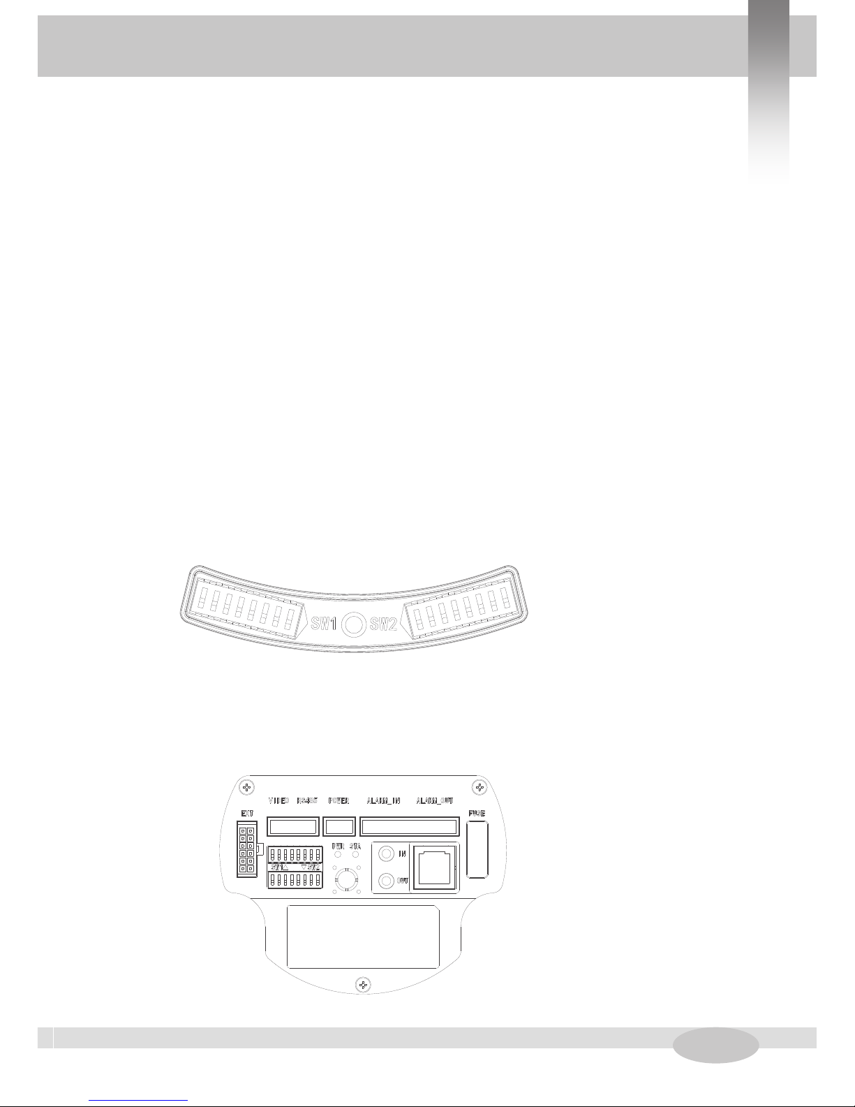
● DIP Switch Setting
Before the dome is installed, please finish the setup of the communication
Protocol, baud rate and dome address. Set the DIP switch inside the dome body, please un-
screw the protection cap out, there is two DIP switch.
Product Overview 1.2 Functions
Page7
Method One
●Cable Definition:
BNC Connector: Video Coaxial Cable
Power Connector: DC12V
Red: RS485A
Yellow: RS485B
Method Two
●Protocol Setup
Our IR speed dome supports two protocols including Pelco P, Pelco D.
All of them supports baud rate of 9600bps、4800bps、2400bps.
Set the No.1~4 dip switch for the protocol configuration.
● Baud Rate Setup
Set the No.5~6 dip switch for the baud rate configuration.
●Dome Address Encoding sheet
SW1 DIP Switch is used to set dome address. Address setting adopts binary way, the 8th dip
is MSD, and the 1st dip is LSD.
SW1— Dip switch for the
dome address
SW2— Dip switch for the
dome protocol
Product Overview 1.2 Functions

Page8
ADD SW-1 SW-2 SW-3 SW-4 SW-5 SW-6 SW-7 SW-8
1 1 0 0 0 0 0 0 0
2 0 1 0 0 0 0 0 0
3 1 1 0 0 0 0 0 0
4 0 0 1 0 0 0 0 0
5 1 0 1 0 0 0 0 0
6 0 1 1 0 0 0 0 0
7 1 1 1 0 0 0 0 0
8 0 0 0 1 0 0 0 0
9 1 0 0 1 0 0 0 0
10 0 1 0 1 0 0 0 0
11 1 1 0 1 0 0 0 0
12 0 0 1 1 0 0 0 0
13 1 0 1 1 0 0 0 0
14 0 1 1 1 0 0 0 0
15 1 1 1 1 0 0 0 0
16 0 0 0 0 1 0 0 0
17 1 0 0 0 1 0 0 0
18 0 1 0 0 1 0 0 0
19 1 1 0 0 1 0 0 0
20 0 0 1 0 1 0 0 0
21 1 0 1 0 1 0 0 0
22 0 1 1 0 1 0 0 0
23 1 1 1 0 1 0 0 0
24 0 0 0 1 1 0 0 0
25 1 0 0 1 1 0 0 0
26 0 1 0 1 1 0 0 0
27 1 1 0 1 1 0 0 0
Protocol SW2-1SW2-2SW2-3SW2-4
PELCO P ON OFF OFF OFF
PELCO D OFF ON OFF OFF
Reserved …………
Protocol SW2-1SW2-2SW2-3SW2-4
PELCO P ON OFF OFF OFF
PELCO D OFF ON OFF OFF
Reserved …………
Product Overview 1.2 Functions
Page9
Red 485A[+]
Yellow 485B[-]
yellow & green ground
wire
power socket
BNC connector
There is no further notice when the specification parameters are changed.
28 0 0 1 1 1 0 0 0
29 1 0 1 1 1 0 0 0
30 0 1 1 1 1 0 0 0
31 1 1 1 1 1 0 0 0
32 0 0 0 0 0 1 0 0
………………………
253 1 0 1 1 1 1 1 1
254 0 1 1 1 1 1 1 1
Product Overview 1.2 Functions
1.3 Technical Data
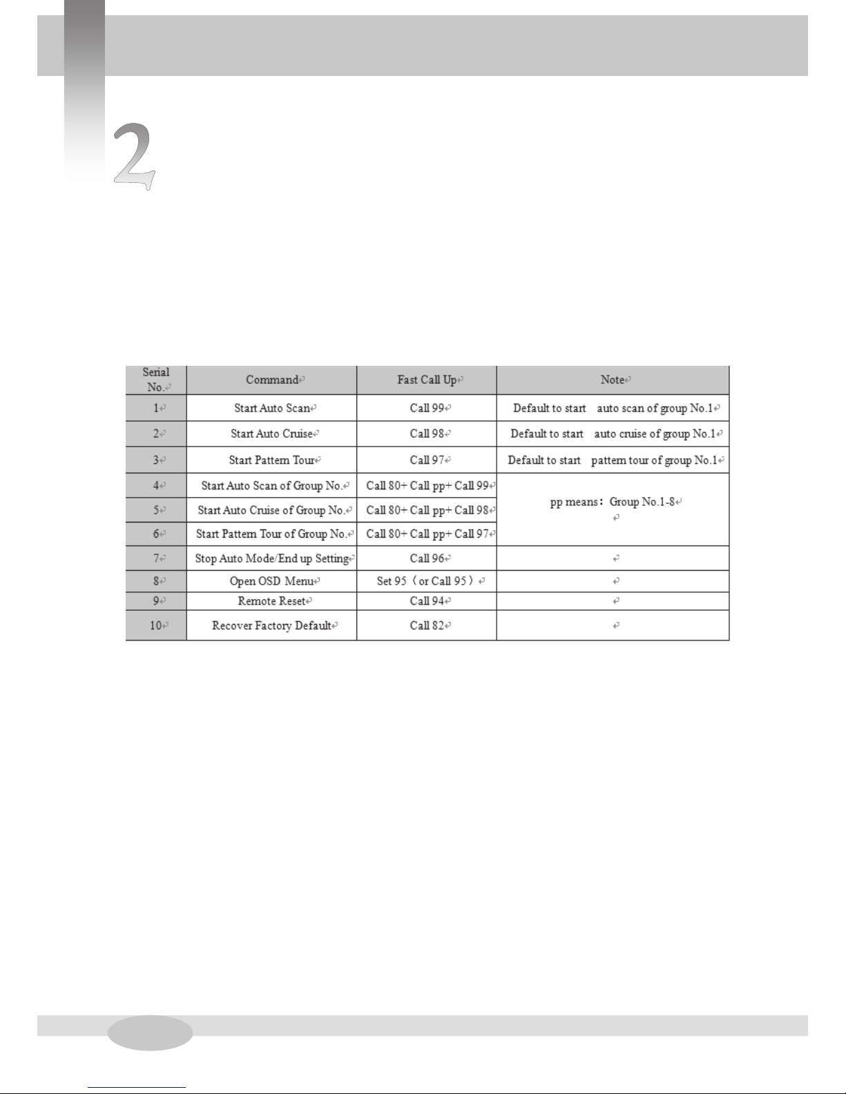
Page10
Common Operation
2.1 Common Operation
Main Functions Fast Call Up
Our dome supports 256 preset positions. You can activate some special functions by call-
ing upon code number 65-99.
OSD Menu Operations:
1, Call Preset 95 to enter the main OSD menu (or call preset No.1 two times continu-
ously within two seconds)
2, Control the joystick to move the cursor around the menu
3, Press “Iris Open” to enter the menu for selections
4, Move the joystick up and down to select the item
5,Press “Iris Open” to confirm the selection
6, Press “Iris Close” to cancel the selection
Common Operation

Page11
OSD Menu
The user can check the dome information as
required. The system information includes: version,
dome address, baud rate, temperature, voltage.
Use the following steps to display the System
Information screens:
1. Click up/down to choose
2. Press IRIS OPEN. The INFORMATION screen
opens.
MAIN
( INFORMATION )
DOME SETTINGS
MOTION
RESTART
FACTORY
EXIT
(VERSION:VR210P-200 )
ADDRESS:001
BAUDRATE:2400
TEMPERATURE:30
VOLTAGE:12.1V
BACK EXIT
INFORMATION
3.1 INFORMATION
OSD Menu

Page12
OSD Menu
The user can make settings through DOME
SETTING, and set the IR LED working mode.
1. CONTROL Mode:
AUTO: IR LED will be opened or closed automati-
cally according to the light conditions.
Open: IR LED forcedly open
Close: IR LED forcedly close
2. SENSITIVITY:
When IR LED Control mode is auto, the smaller
the number is, the lower light of the environment
will be when the IR LED is on.
3. NEAR POWER: 1-100 adjustable
4. FAR POWER: 1-100 adjustable
5. COMPENSATION: class 0-3, when IR LED
near light open, far light will be on according to
power setting.
MAIN
INFORMATION
( DOME SETTINGS )
MOTION
RESTART
FACTORY
EXIT
DOME SETTINGS
(IR LED)
( WIPER )
( IDLE )
( ALARM )
(PRIVACY MASK)
(ADVANCED)
(OTHERS)
BACK EXIT
( CONTROL : AUTO )
SENSE :—-(-)-4/6
NEAR POWER : 100
FAR POWER : 100
COMPENSATION :0
BACK EXIT
IR LED SETTING
3.2.1 IR LED
OSD Menu
Page13
OSD Menu
The user can make adjustment for the wiper
under this menu (suitable for wiper-equipped
dome)
1.NUMBER : Move the cursor to “NUMBER”
and press IRIS OPEN to enter the setup of Wiper
Number. Move the joystick up and down to select
number (1-10),then press IRIS OPEN to confirm.
2.SPEED: Move the cursor to “SPEED” and IRIS
OPEN to enter the setup of Wiper Speed. Move
the joystick up and down to select
“HIGH” ,“MID ”OR “ LOW”, then press IRIS
OPEN to confirm.
3.AUX ON:
Move the cursor to “AUX ON", click IRIS
ON to enter setting mode, move the joystick up
and down to select “ON”,1/2 status, click IRIS
OPEN to confirm.
4.RESET:
When the wiper hide the camera vision,
move cursor to “RESET", click IRIS OPEN,
wiper will return the initial position.
5.ACTIVATE:
Move cursor to “ACTIVATE”, click IRIS
OPEN, wiper will be enabled.
Note: calling Preset 71 will enable the wiper.
MAIN
INFORMATION
( DOME SETTINGS )
MOTION
RESTART
FACTORY
EXIT
DOME SETTINGS
(IR LED)
( WIPER )
( IDLE )
( ALARM )
(PRIVACY MASK)
(ADVANCED)
(OTHERS)
BACK EXIT
( NUMBER:03 )
SPEED:MID
AUX ON:AU*1
RESET
ACTIVATE
BACK EXIT
WIPER
3.2.2 WIPER
OSD Menu
Page14
OSD Menu
IDLE setting means if there is no command
for the dome for a period of time, the dome will
run the actions as defined.
1. TIME: Move the cursor to “TIME” and press
IRIS OPEN to enter, and move the joystick up
and dome to select among 30 sec, 1min, 5 min,
10 min and 30 min. And press IRIS OPEN to
confirm.
2.ACTION: Move the cursor to “ACTION” and
press IRIS OPEN to enter. Move the joystick to
select the actions including” NONE, PRESET,
SCAN, SEQUENCE, PATTERN. Press IRIS
OPEN to confirm.
MAIN
INFORMATION
( DOME SETTINGS )
MOTION
RESTART
FACTORY
EXIT
DOME SETTINGS
(IR LED)
( WIPER )
( IDLE )
( ALARM )
(PRIVACY MASK)
(ADVANCED)
(OTHERS)
BACK EXIT
TIME :10MIN
ACTION:NONE
BACK EXIT
IDLE
3.2.3 IDLE
OSD Menu
Page15
OSD Menu
The dome system has 4 alarm inputs and 2 alarm
output. (optional function). When an alarm is re-
ceived, an input signal to the dome triggers the user
defined action (such as presets, patterns, etc.), and at
meantime the alarm output signals is activated.
ALARM NO.: Move the cursor to ALARM NO..
Click Iris + to enter and click up or down button to
select the alarm input no. (Channel 1 and Channel 2)
INPUT STATE: Set the alarm contact status. There
are two input states, OPEN and CLOSE.
ALARM MODE:
ACTION: Set the alarm action:
OFF: alarm function is deactivated.
ON: alarm function is activated.
AUTO: auto alarm function will be activated and
deactivated between start time and stop time.
ACTION: Set the alarm action:
None: (default) No action
Preset: Dome goes to preset. (Default as Preset 1)
Scan: Dome starts auto scan (Default as auto scan 1)
SEQ: Dome runs auto cruise (Default as auto cruise
1)
Pattern: Dome runs pattern (Default as Pattern 1)
ALARM OUT: Move the cursor to ALARM OUT.
Click IRIS + to enter and click up or down button to
select alarm output channels among “OFF”
“OUTPUT1” “OUTPUT2” “ALL”, which is used to
set linkage alarm output switch after receiving effec-
tive alarm input signals.
RESET DELAY: Move the cursor to the ALARM
OUT. Click IRIS + to enter and click up or down
button to select reset delay among “10SEC” “30SEC”
“1MIN” “5MIN” “10MIN”.Which mean the time of
the speed dome from detecting alarm signals to alarm
reset and return to normal. The setting is valid under
AUTO ALARM MODE.
MAIN
INFORMATION
( DOME SETTINGS )
MOTION
RESTART
FACTORY
EXIT
DOME SETTINGS
(IR LED)
( WIPER )
( IDLE )
( ALARM )
(PRIVACY MASK)
(ADVANCED)
(OTHERS)
BACK EXIT
ALARM NO.:1
CONTACT:NO
ALARM MODE:OFF
ACTION:NONE
ALARM OUT:OFF
RESET DELAY:10SEC
BACK EXIT
ALARM SETTING
3.2.4 ALARM
OSD Menu

Page16
OSD Menu
Camera support Focus limit function, option
is10cm、30cm、1m、1.5m、3m、6m INFINITE
MAIN
DOME SETTINGS
(IR LED)
( WIPER )
( IDLE )
( ALARM )
(PRIVACY MASK)
(ADVANCED)
(OTHERS)
BACK EXIT
ADVANCED
FOCUS MODE:PUSH
FOCUS LIMIT:1M5
VIDEO TYPE:PAL
(AUX)
(SOFT LIMIT)
(DOME SPEED)
(POWER ON ACTION)
(TILT ANGLE)
BACK EXIT
3.2.6-2 FOCUS LIMIT
INFORMATION
( DOME SETTINGS )
MOTION
RESTART
FACTORY
EXIT
OSD Menu
Page17
Camera support VIDEO TYPE, PAL and
NTSC.
OSD Menu
3.2.6-3 VIDEO TYPE
MAIN
DOME SETTINGS
(IR LED)
( WIPER )
( IDLE )
( ALARM )
(PRIVACY MASK)
(ADVANCED)
(OTHERS)
BACK EXIT
ADVANCED
FOCUS MODE:PUSH
FOCUS LIMIT:1M5
VIDEO TYPE:PAL
(AUX)
(SOFT LIMIT)
(DOME SPEED)
(POWER ON ACTION)
(TILT ANGLE)
BACK EXIT
INFORMATION
( DOME SETTINGS )
MOTION
RESTART
FACTORY
EXIT
OSD Menu

Page18
OSD Menu
Camera support Focus limit function, option
is10cm、30cm、1m、1.5m、3m、6m INFINITE
MAIN
DOME SETTINGS
(IR LED)
( WIPER )
( IDLE )
( ALARM )
(PRIVACY MASK)
(ADVANCED)
(OTHERS)
BACK EXIT
ADVANCED
FOCUS MODE:PUSH
FOCUS LIMIT:1M5
VIDEO TYPE:PAL
(AUX)
(SOFT LIMIT)
(DOME SPEED)
(POWER ON ACTION)
(TILT ANGLE)
BACK EXIT
3.2.6-2 FOCUS LIMIT
INFORMATION
( DOME SETTINGS )
MOTION
RESTART
FACTORY
EXIT
OSD Menu

Page19
Camera support VIDEO TYPE, PAL and
NTSC.
OSD Menu
3.2.6-3 VIDEO TYPE
MAIN
DOME SETTINGS
(IR LED)
( WIPER )
( IDLE )
( ALARM )
(PRIVACY MASK)
(ADVANCED)
(OTHERS)
BACK EXIT
ADVANCED
FOCUS MODE:PUSH
FOCUS LIMIT:1M5
VIDEO TYPE:PAL
(AUX)
(SOFT LIMIT)
(DOME SPEED)
(POWER ON ACTION)
(TILT ANGLE)
BACK EXIT
INFORMATION
( DOME SETTINGS )
MOTION
RESTART
FACTORY
EXIT
OSD Menu
Page20
OSD Menu
The user can set up the auxiliary output to trig-
ger other devices to realize camera function expan-
sion.
1. AUX *1 and AUX*2 with on/off
Move the cursor to AUX and press IRIS
OPEN to enter to select “ON” or “OFF” to enable
or disable this function.
FOCUS MODE:PUSH
FOCUS LIMIT:1M5
VIDEO TYPE:PAL
(AUX)
(SOFT LIMIT)
(DOME SPEED)
(POWER ON ACTION)
(TILT ANGLE)
BACK EXIT
MAIN
INFORMATION
( DOME SETTINGS )
MOTION
RESTART
FACTORY
EXIT
DOME SETTINGS
(IR LED)
( WIPER )
( IDLE )
( ALARM )
(PRIVACY MASK)
(ADVANCED)
(OTHERS)
BACK EXIT
ADVANCED
3.2.6-4 AUX
AUX
AUX *1 : OFF
AUX *2 : OFF
BACK EXIT
OSD Menu
Table of contents
Popular Security Camera manuals by other brands

iBeam
iBeam OnSite Fixed Series installation instructions

VADDIO
VADDIO WallView Installation and user guide

COP-USA
COP-USA CZ22RC Specifications

A1 Security Cameras
A1 Security Cameras Uniview IPC2125LR3-PF40M-D quick guide

Bosch
Bosch LTC 7935 instruction manual

Platinum CCTV
Platinum CCTV KC-DVR1080P Setup manual


