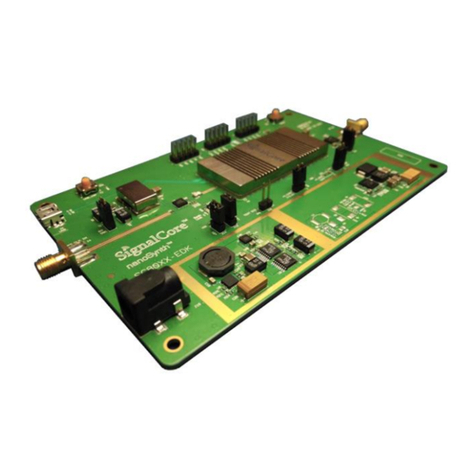
SIGNALCORE nanoSynth SC801A User manual

Rev 1.0 | nanoSynth-HB EDK Guide SignalCore, Inc.
Table of Contents
1Verifying the Contents of Your Shipment..............................................................................................3
2nanoSynth-HB Evaluation Board Description ........................................................................................4
3Control Software and Device Driver ......................................................................................................5
4Using the SC801A/SC802A Soft Front Panel..........................................................................................7
4.1 The Control Tab...........................................................................................................................10
4.2 The Configuration Sweep/List Tab...............................................................................................12
4.2.1 List Mode Configuration Sub-Window ................................................................................12
4.3 List Entry Tab...............................................................................................................................13
4.4 The Device Information Tab ........................................................................................................14
5Using the SC803A Soft Front Panel......................................................................................................14
5.1 The Control Window ...................................................................................................................14
5.2 The Information Window ............................................................................................................15
6Revision Table......................................................................................................................................16

©2022 | nanoSynth-HB EDK Guide Rev 1.0
3
Verifying the Contents of Your Shipment
1Verifying the Contents of Your Shipment
The contents of the product package should include the following items:
•One nanoSYnth-HB EDK board kit
•One 12V power supply wall adapter
•Two USB cables
•One USB flash drive contains software, board design files, and product documents
Inspect the shipping carton for visible damage. If carton is damaged, please notify both the
carrier and SignalCore immediately.
The SC801A EDK ships in antistatic packaging to prevent damage from electrostatic discharge
(ESD). The device should always be stored inside an antistatic bag when it is not in use, as ESD can
cause damage to the electronic components on the board. Properly ground yourself and use ESD
good practices when handling the product.
Open the shipping carton and remove all contents. If the contents show visible damage and/or
are missing, please contact SignalCore immediately.
ESD CAUTION

©2022 | nanoSynth-HB EDK Guide Rev 1.0
5
Control Software and Device Driver
3Control Software and Device Driver
The nanoSynth-HB EDK comes with a USB flash drive that contains all software needed to control
and program the onboard nanoSynth devices, namely the SC801A or SC802A as well as the SC803A
reference source. Insert the USB drive into the host computer and navigate to the device_name\win
directory that contains the setup files for the devices. If the host operating system is 64 bits, run the
*Setup64*.exe executable, else run the *Setup32*.exe excutable for 32 bits OS. These setup files for
the device will install a software front panel (SFP) to quickly control the device, programming API for
software development, and the necessary drivers. Follow the instructions to finish the installation.
Note that the LabVIEW 2010 Runtime has to be installed into the system to enable the SFP to work,
and there are a couple of ways to do that. You may choose to install it during the software
installation process, where a Dependencies window (Figure 2) would prompt to select the
installation of the LabVIEW runtime (LVRT). If you did not remember to install the LVRT during
software installation, you may navigate the USB drive to the \LabVIEW Run-Time
Engine\LVRTE2010_f2Patch-64 and run the setup.exe excutable for 64 bits OS.
Item
Description
A
SC803A reference source module
B
Reference input SMA connector. When J11, the REF_CLK_SELECT, pins are
jumped this reference is passed to the SC803A reference source module,
otherwise this signal is passed directly to the SC801A/SC802A. The reference
frequency must be 200 MHz if clocking the SC801A/SC802A directly. See the
SC803A for allowable frequencies and recommended input power.
C
Digital I/O pins for serial communication for the respective device. See
schematics at the end of this document.
D
12V power jack, 2.5x5.5mm
E
Mini-B type USB connector for USB communication to the devices
F
Reference flash erase. Do not jump/short pin together. Doing so and depressing
reset will erase the device flash memory.
G
Synthesizer flash erase. Do not jump/short pin together. Doing so and
depressing reset will erase the device flash memory.
H
SC801A/SC802A synthesizer module with attached heatsink
I
Reference Clock Select. Selects to use the onboard SC803A (pins jumped) or an
external 200 MHz source (pins open) for the SC801A/SC802A. If external clock
source is used, the recommended power is 7-10 dBm.
J
RF Out
K
10 MHz Reference out from the SC803A.
L
Reference out (100/200 MHz) from the SC803A.
M
SC801A/802A reset button.
N
SC803A reset button
O
Configuration switches for the SC801A/SC802A. Configuration switches for the
SC803A. For more information see product datasheet.
P
Configuration switches for the SC803A. For more information see product
datasheet.
Table 1

Rev 1.0 | nanoSynth-HB EDK Guide SignalCore, Inc.
Once software installation is completed and the device is powered up and connected to the host via
USB, it will show up in the Windows Device Manager as a SignalCore USB Device and the SFP will
appear in the [Start] menu. See Figure 3.
Figure 2 Prompt to install LabVIEW runtime

©2022 | nanoSynth-HB EDK Guide Rev 1.0
7
Using the SC801A/SC802A Soft Front Panel
4Using the SC801A/SC802A Soft Front Panel
The SFP can be launched by clicking the START->Programs->SignalCore->nanoSynth-HB SFP once the
control software and device driver are installed. This executable is written in LabVIEW and its source
code is available in the installation directory. The LabVIEW function library used to develop this
application is also available in the installation directory, and its functions are simply wrappers of the
API (nanohb.dll). The startup screen of the SFP is shown in Figure 4, which show the devices
Figure 3Device Manager Screen and [Start]

Rev 1.0 | nanoSynth-HB EDK Guide SignalCore, Inc.
detected in the host computer in a popup window. Pull down on the menu to select the device
corresponding serial number and interface.
Figure 4. SFP launch
The very first tab in the SFP window is the [Control] tab. You may select other tabs by clicking the
upper left box as shown in Figure 5 below.
Figure 5 Tab listing various windows to view
4.1 The Control Tab
This tab has most of the control function for the device you may change the frequency, adjust the
signal phase, configure the synthesizer modes, and apply the software trigger to start, stop, or step
the list or sweep frequencies. The behavior of the trigger is set up by the list mode configuration
function and is discussed in section 4.2. These controls are on the left side of the tab window as
seen in Figure 6. Details on the synthesizer mode setting are as follows:

©2022 | nanoSynth-HB EDK Guide Rev 1.0
11
Using the SC801A/SC802A Soft Front Panel
•RF Mode –This toggles the device to generate a fix frequency or set it up ready for
sweep/list mode triggering.
•Loop Gain –This toggles the synthesizer phase lock-loop gain between normal and
narrow. Narrow loop gain helps to suppress farther out spurious signals, spurs greater
than 1 MHz away from carrier center. However, this could increase noise in the spectral
region close the carrier.
•Lock Mode –The synthesizer uses 2 phase lock modes for synthesis, Harmonic and
Integer-N. Harmonic mode provides the best phase noise however spurs signals may occur
more frequent. Integer-N mode has less spur occurrences, but the close-in phase noise is
higher. The user may choose between the modes and weigh the benefits of that choice for
a particular application.
•Resolution –This selects the frequency resolution between 1 Hz or 1 mHz, the default is 1
Hz. Choosing 1 mHz places more computational accuracy on the device’s 32 bit
microcontroller and the resulting frequency is more likely to have rounding off errors to
the order of 10e-5 Hz. This rounding off error is less likely for 1 Hz resolution
computations.
•SpurSupp –This enables and disables spur suppression. When it is enabled, the device
tries to bounce between the 2 lock modes, as mentioned above, to avoid noticeable spurs
using a lookup table.
On the right side of the tab window are the current device operating status indicators, as well as
the current temperature of the device. To update the device, select [Fetch Status] and set the time
interval between each status update from the device. The [Fetch Status] turns bright green if it is
active.
Figure 6 The control window

Rev 1.0 | nanoSynth-HB EDK Guide SignalCore, Inc.
4.2 The Configuration Sweep/List Tab
Figure 7 The Sweep configuration window
This tab window is used to configure the device to automatically change the frequencies based on
a list or “sweep frequency parameters”. In this window we configure the sweep list of frequencies
using 3 parameters: the start and stop frequencies, and the step frequency size. These parameters
are inside the “Sweep Freq Parameter” sub-window, see Figure 7. The dwell period sets the time
that the signal spends at a frequency before changing to the next. The sweep/list cycles value sets
the number of cycles the sweep goes through from beginning to end before stopping. If its value is
set to zero, the sweep will cycle indefinitely. The number of sweep points is calculated from the 3
sweep frequency parameters.
4.2.1 List Mode Configuration Sub-Window
This sub-window sets the behavior of the sweep, and its parameters are discussed below.
4.2.1.1 Sweep/List
The parameter instructs the device to either use the frequency points calculated by the 3 sweep
parameters mentioned above, namely the start, stop, and step frequencies, or from a user input
list of frequencies. User input list will be discussed in the next tab section.
4.2.1.2 Sweep Direction
The sweep can be chosen to start at the beginning of a list and incrementally step to the end or
vice versa.
4.2.1.3 Sweep Waveform
The list of frequency points may be swept in a saw-tooth or triangular manner. If sawtooth is
selected, the device will return to the starting point upon reaching the last frequency point.
Plotting frequency versus time reveals a sawtooth pattern. If triangular is selected, the device will
sweep linearly from the starting point, then reverse its direction after the last (highest or lowest)
frequency and sweeps backward toward the start point, mapping out a triangular waveform on a
frequency versus time graph.

©2022 | nanoSynth-HB EDK Guide Rev 1.0
13
Using the SC801A/SC802A Soft Front Panel
4.2.1.4 Trigger Source
This selects whether the trigger source is software or hardware. If the source is hardware, a
falling edge on Trigger-In pin will trigger the device. Hardware trigger does not have the variable
latency associated with software trigger, and thence it provides better timing control.
4.2.1.5 Trigger Mode
If this mode is set to “start/stop”, the first trigger is be interpreted as a start signal to begin the
sweep process and progressively move through the frequency points with a delay. A subsequent
trigger will stop the sweep. If it is set to “step” then each trigger will only advance the frequency
once; the signal remains indefinitely until the next trigger.
4.2.1.6 Return to Start
If this is select, the device returns to the start frequency of the sweep after a set number of
cycles, otherwise it will remain at the end frequency of the sweep.
4.2.1.7 Trigger Out State
If trigger out is enable, the Trigger-Out pin pulses once for every frequency change.
4.3 List Entry Tab
This is where the list of frequencies and their corresponding delays are entered, frequency is
entered in Hz and delay in milliseconds. A maximum of 2048 points can be entered, see Figure 8.
Figure 8 List entry window
Once the frequencies and corresponding delays are entered in the columns, click the [Download
to Buffer] button to write the data points to the device memory buffer. If the user wants to store
this data permanently in the device EEPROM memory, click the [Save Buffer to EEPROM] button.
To retrieve EEPROM data into program memory, click the [Read EEPROM to Buffer] button.

Rev 1.0 | nanoSynth-HB EDK Guide SignalCore, Inc.
4.4 The Device Information Tab
Figure 9 The device information window
This tab window shows information pertaining to the device such as serial number, model
information, hardware and firmware revision, manufactured date, and serial port configuration. If
the UART Pin is physically grounded (zero state), its baud rate defaults to 57600. If the pin is
pulled high (set to 1) and upon powerup the baud rate will be set to the rate stored in memory as
default. To set a new baud rate, first change the rate by selecting the “pin Baudrate”, followed by
clicking [Change Baudrate], and finally clicking [Set As Default]. When the [Set As Default] button
is clicked, all the current settings in all the tabs will be stored and used as the default powerup
state.
5Using the SC803A Soft Front Panel
5.1 The Control Window
The control tab, Figure 10, shows the operating state of the device such as the output and input
reference frequencies, the reference configuration, and the other current status. The device
configuration is set via hardware pins by default. However, these pins can be overridden by
selecting ‘True’ for “OverrideHwPins”. Doing so allow the user to set the different reference input
and output frequencies, and lock and unlock from external reference sources programatically.

Rev 1.0 | nanoSynth-HB EDK Guide SignalCore, Inc.
6Revision Table
Revision
Revision Date
Description
1.0
8/2/2022
Initial Release
This manual suits for next models
2
Table of contents
Other SIGNALCORE Microcontroller manuals
Popular Microcontroller manuals by other brands
Nuvoton
Nuvoton NuMicro series user manual
NXP Semiconductors
NXP Semiconductors S12ZVML-MINIKIT quick start guide
Infineon
Infineon XMC7000 Series quick start guide
Cypress MicroSystems
Cypress MicroSystems CY3215-DK Getting started guide
Dave Embedded Systems
Dave Embedded Systems XELK quick start guide
Emerson
Emerson Vilter Vission 20/20 Operation and service manual


