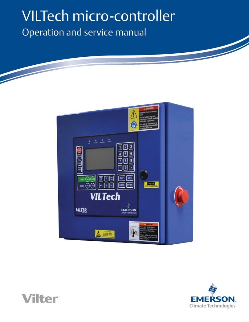
Emerson Vilter Vission 20/20 Operation manual

Vission 20/20TM Micro-controller
Operation and service manual • Version 2.7


Vission 20/20 • Operation and Service Manual • Emerson • 35391SC 2.7
READ CAREFULLY BEFORE OPERATING YOUR COMPRESSOR.
The following instructions have been prepared to assist in operation of VilterTM Vission 20/20TM micro-controllers.
The entire manual should be reviewed before attempting to operate.
VilterTM micro-controllers are thoroughly inspected at the factory. However, damage can occur in shipment.
For this reason, the equipment should be thoroughly inspected upon arrival. Any damage noted should be
reported immediately to the Transportation Company. This way, an authorized agent can examine the unit,
determine the extent of damage and take necessary steps to rectify the claim with no serious or costly delays.
At the same time, the local VilterTM representative or the home office should be notified of any claim made.
All inquires should include the VilterTM sales order number, compressor serial and model number. These can be
found on the compressor nameplate on the compressor.
All requests for information, services or parts should be directed to:
VilterTM Manufacturing LLC
Customer Service Department
5555 South Packard Ave
Cudahy, WI 53110 USA
Telephone: 1-414-744-0111
Fax:1-414-744-3483
E-mail: info.vilter@emerson.com
Equipment Identification Numbers:
Vilter Order Number: _______________________Software Version: _________________
Important Message
i


TOC - 1
Vission 20/20 • Operation and Service Manual • Emerson • 35391SC 2.7
Table of Contents
Section Title Section Number
Important Message................................................................................................................................i
How To Use This Manual.........................................................................................................................TOC-12
Section 1 • Operational Flow Charts
Requirements to Start Compressor ........................................................................................................1-1
Critical Compressor Run Logic at Compressor Start................................................................................1-1
Compressor Amperage Load Limiting ....................................................................................................1-2
High Discharge Pressure Load Limiting..................................................................................................1-2
Suction Pressure Override Load Limit During Temperature Control ........................................................1-2
Section 2 • Installation Recommendations
Proper Wiring Sizing ..............................................................................................................................2-1
Voltage Source ......................................................................................................................................2-1
Grounding .............................................................................................................................................2-2
Mixing Voltages .....................................................................................................................................2-2
DC signals..............................................................................................................................................2-2
Wiring Methods.....................................................................................................................................2-3
Best Practices.........................................................................................................................................2-4
Section 3 • Hardware Architecture
Overview ...............................................................................................................................................3-1
Digital Input/Output (I/O)......................................................................................................................3-1
Analog Inputs ........................................................................................................................................3-6
Analog Outputs .....................................................................................................................................3-7
Digital & Analog I/O Boards Layout.........................................................................................................3-8
Digital Output Boards ............................................................................................................................3-9
Digital Input Boards ...............................................................................................................................3-10
Digital In-Out Boards .............................................................................................................................3-11
Analog Input Boards ..............................................................................................................................3-12
Analog Input Jumper Tables ...................................................................................................................3-13
Analog Output Boards ...........................................................................................................................3-15
Section 4 • Main Screen
Overview ...............................................................................................................................................4-1
Top Status Bar........................................................................................................................................4-2
Parameter Bar........................................................................................................................................4-3
Bottom Status Bar..................................................................................................................................4-5
Splash Screen.........................................................................................................................................4-6
Step VI Screen........................................................................................................................................4-7
SOI Solenoid Screen ...............................................................................................................................4-8
Configurable Main Screen ......................................................................................................................4-9
Section 5 • Menu Screen
Overview ...............................................................................................................................................5-1
Navigation Buttons ................................................................................................................................5-1
Section 6 • Compressor Control
Overview ...............................................................................................................................................6-1
Suction Pressure Control, Process Temperature Control, Process Pressure Control
and Discharge Pressure Control .............................................................................................................6-1
Auto-Cycle .............................................................................................................................................6-2

TOC - 2 Vission 20/20 • Operation and Service Manual • Emerson • 35391SC 2.7
Variable Frequency Drive (VFD)..............................................................................................................6-5
Oil Restriction Solenoid..........................................................................................................................6-7
Rapid Cycling VFD Control......................................................................................................................6-8
Pumpdown Control................................................................................................................................6-9
Pulldown Control...................................................................................................................................6-10
Active Control Mode ..............................................................................................................................6-11
Load Anticipating...................................................................................................................................6-11
Oil Control .............................................................................................................................................6-12
Stop Load & Force Unload ......................................................................................................................6-14
Capacity Slide Triggered Outputs...........................................................................................................6-15
Volume Slide Position Offset ..................................................................................................................6-15
Soft Load ...............................................................................................................................................6-16
Liquid Injection ......................................................................................................................................6-16
Dual Liquid Injection ..............................................................................................................................6-18
Liquid Injection Outlet Port Direction.....................................................................................................6-19
VI Control - Twin Screw ..........................................................................................................................6-20
Fixed VI..................................................................................................................................................6-20
Continuos VI ..........................................................................................................................................6-21
Step VI... ................................................................................................................................................6-22
Section 7 • Alarms and Trips
Overview ...............................................................................................................................................7-1
Warnings. ..............................................................................................................................................7-1
Inhibits. .................................................................................................................................................7-1
Alarms... ................................................................................................................................................7-2
Trips ......................................................................................................................................................7-2
Freeze Screen ........................................................................................................................................7-2
Logging - Event List ..... ..........................................................................................................................7-2
Setpoints .... ..........................................................................................................................................7-2
Add Oil to the Middle Sight Glass ...........................................................................................................7-8
Analog AUX In 1-16................................................................................................................................7-8
Compressor Interlock Trip......................................................................................................................7-8
Digital AUX In 1-8...................................................................................................................................7-8
Discharge Pressure
High Discharge Pressure ........................................................................................................................7-9
Low Discharge Pressure .........................................................................................................................7-9
Discharge Superheat Temperature
High Discharge Superheat Start Temp.................................................................................................... 7-9
High Discharge Superheat Rise Temp .....................................................................................................7-9
High Discharge Superheat Run Temp .....................................................................................................7-10
Discharge Temperature
High Discharge Temp.............................................................................................................................7-10
Low Discharge Temp ..............................................................................................................................7-10
Emergency Shutdown Activated ............................................................................................................7-10
False Start ..............................................................................................................................................7-10
Filter Differential Pressure
High Filter Differential Pressure..............................................................................................................7-11
Level Shutdown .....................................................................................................................................7-11
Motor Current........................................................................................................................................7-11
Oil Filter Inlet Pressure. ..........................................................................................................................7-12
Low Oil Filter Inlet Pressure ....................................................................................................................7-12
Low Oil Filter Outlet Pressure .................................................................................................................7-12
High Oil Injection Temp..........................................................................................................................7-12
Low Oil Injection Temp...........................................................................................................................7-12
Section Title Section Number
Table of Contents

TOC - 3
Vission 20/20 • Operation and Service Manual • Emerson • 35391SC 2.7
Oil Level #1 or #2....................................................................................................................................7-12
Oil Level Trip after Stop ..........................................................................................................................7-13
Oil Over Pressure ...................................................................................................................................7-13
Low Oil Pressure.....................................................................................................................................7-13
Start Low Oil Pressure ............................................................................................................................7-14
High Oil Separator Temp........................................................................................................................7-14
Low Oil Separator Temp .........................................................................................................................7-14
Pre-Lube Pressure ..................................................................................................................................7-15
Process Pressure ....................................................................................................................................7-15
High Process Pressure ............................................................................................................................7-15
Low Process Pressure .............................................................................................................................7-16
Process Temperature
High Process Temperature .....................................................................................................................7-16
Low Process Temperature ......................................................................................................................7-16
Remote Comm Time-Out.......................................................................................................................7-16
Low Run Pressure Ratio ..........................................................................................................................7-17
SOI Oil Pressure
SOI Low Oil Pressure ..............................................................................................................................7-17
SOI Low Pressure Ratio...........................................................................................................................7-17
Starter....................................................................................................................................................7-17
Suction Pressure
Low Suction Pressure .............................................................................................................................7-17
Suction Superheat Temperature
Low Suction Superheat ..........................................................................................................................7-18
Suction Temperature
Low Suction Temp..................................................................................................................................7-18
Volume Position Trip ..............................................................................................................................7-18
Section 8 • Timers
Overview ...............................................................................................................................................8-1
Timer Setpoints .....................................................................................................................................8-1
Section 9 • Compressor Scheduling
Overview ...............................................................................................................................................9-1
Scheduling Setpoint...............................................................................................................................9-1
Section 10 • Compressor Sequencing
Overview ...............................................................................................................................................10-1
Compressor Sequencing Table ............................................................................................................... 10-1
Status Symbols ......................................................................................................................................10-3
Suction Pressure Control Setpoints ........................................................................................................10-4
Pressure Setpoints .....................................................................................................................10-4
Capacity Load/Unload Timers ....................................................................................................10-4
Process Control Setpoints - Temperature................................................................................................10-5
Temperature Setpoints ..............................................................................................................10-5
Capacity Load/Unload Timers ....................................................................................................10-5
Process Control Setpoints - Pressure ......................................................................................................10-6
Pressure Setpoints .....................................................................................................................10-6
Capacity Load/Unload Timers ....................................................................................................10-6
Discharge Pressure Control Setpoints.....................................................................................................10-7
Pressure Setpoints .....................................................................................................................10-7
Capacity Load/Unload Timers ................................................................................................................10-7
Section Title Section Number
Table of Contents

TOC - 4 Vission 20/20 • Operation and Service Manual • Emerson • 35391SC 2.7
Devices List ............................................................................................................................................10-8
Devices List Columns .................................................................................................................10-8
View Detected Devices ..............................................................................................................10-9
Add Device ............................................................................................................................................10-10
Delete Device.........................................................................................................................................10-11
Test Connection.....................................................................................................................................10-12
Sync Sequencing Parameters .................................................................................................................10-13
Compressor Sequencing Events Log.......................................................................................................10-14
Events List Columns ...................................................................................................................10-14
Configuration Overview.........................................................................................................................10-15
Setting Up The Slave Compressors For Sequencing ....................................................................10-15
Setting Up The Master Compressor............................................................................................10-17
Section 11 • Condenser Control
Overview ...............................................................................................................................................11-1
Condenser Control Setpoint...................................................................................................................11-1
Step Control...........................................................................................................................................11-2
VFD Settings ..........................................................................................................................................11-3
Section 12 • Service Options
Overview ...............................................................................................................................................12-1
Digital Outputs ......................................................................................................................................12-1
Analog Outputs .....................................................................................................................................12-5
Section 13 • Instruments Calibration
Overview ...............................................................................................................................................13-1
Pressure Control Inputs..........................................................................................................................13-2
Motor Current........................................................................................................................................13-2
Remote Capacity ...................................................................................................................................13-5
Analog Inputs ........................................................................................................................................13-5
Analog Outputs .....................................................................................................................................13-7
Section 14 • Slide Calibration
Overview ...............................................................................................................................................14-1
Capacity Slide Valve Potentiometer........................................................................................................14-1
Volume Slide Valve Potentiometer ......................................................................................................... 14-2
Slide Valve Operation.............................................................................................................................14-2
Calibrate Slide Valve Actuators...............................................................................................................14-3
Command Shaft Rotation.......................................................................................................................14-6
Slide Valve Troubleshooting Guide .........................................................................................................14-7
Slide Valve Actuator Troubleshooting Guide Blink Code .........................................................................14-10
Section 15 • Trend Chart
Overview ...............................................................................................................................................15-1
Chart Operation.....................................................................................................................................15-1
Trend Data Storage ................................................................................................................................15-2
Setup ..................................................................................................................................................15-3
Section 16 • Event List
Overview ...............................................................................................................................................16-1
Event list Columns.................................................................................................................................. 16-1
Section Title Section Number
Table of Contents

TOC - 5
Vission 20/20 • Operation and Service Manual • Emerson • 35391SC 2.7
Table of Contents
Section Title Section Number
Section 17 • Input / Output
Overview ...............................................................................................................................................17-1
QR Code.................................................................................................................................................17-5
Section 18 • Auxiliary Input / Output
Overview ...............................................................................................................................................18-1
Digital Inputs .........................................................................................................................................18-1
Digital Outputs ......................................................................................................................................18-2
Analog Inputs ........................................................................................................................................18-2
Analog Outputs .....................................................................................................................................18-4
Control ..................................................................................................................................................18-4
Section 19 • Configuration
Overview ...............................................................................................................................................19-1
Compressor Identification......................................................................................................................19-1
Units ..................................................................................................................................................19-1
Time & Date...........................................................................................................................................19-2
Communications ...................................................................................................................................19-2
Direct I/O...............................................................................................................................................19-2
Run Permissive.......................................................................................................................................19-2
Serial (Modbus RTU)...............................................................................................................................19-2
Ethernet ................................................................................................................................................19-3
VNC Account .........................................................................................................................................19-3
Anti-Recycle...........................................................................................................................................19-4
Restart On Power Failure........................................................................................................................19-4
Compressor Sequencing ........................................................................................................................ 19-5
Language...............................................................................................................................................19-5
Model & Refrigerant...............................................................................................................................19-5
Compressor Control...............................................................................................................................19-6
Optional Function Settings.....................................................................................................................19-6
Condenser Control.................................................................................................................................19-6
Touchscreen ..........................................................................................................................................19-7
Oil Pump................................................................................................................................................19-8
Oil Cooling.............................................................................................................................................19-8
Motor Current Device ............................................................................................................................19-8
Alarms and Trips ....................................................................................................................................19-8
Special Compressor Settings..................................................................................................................19-8
Daily Auto Back-up Settings ...................................................................................................................19-9
Configurable Main Screen Settings.........................................................................................................19-10
Digital Inputs .........................................................................................................................................19-10
Analog Inputs ........................................................................................................................................19-11
Analog Outputs .....................................................................................................................................19-12
Digital Outputs ......................................................................................................................................19-12
I/O Configuration...................................................................................................................................19-13
Section 20 • Data Backup
Overview ...............................................................................................................................................20-1
Save / Load.............................................................................................................................................20-1
Migrate..................................................................................................................................................20-3
Factory Reset .........................................................................................................................................20-3
Setpoints Report....................................................................................................................................20-4
Database Backup Procedure...................................................................................................................20-5

TOC - 6 Vission 20/20 • Operation and Service Manual • Emerson • 35391SC 2.7
Back-up Database of Original Flashcard..................................................................................................20-5
Replace Original Flashcard with New Flashcard.......................................................................................20-5
Restore Original Database to New Flashcard ..........................................................................................20-5
Record Operating Setpoints and Configuration Information...................................................................20-7
Replace Flashcard...................................................................................................................................20-7
Re-enter Operating Setpoints and Configuration Information ................................................................20-7
Section 21 • Maintenance
Overview ...............................................................................................................................................21-1
Chart ..................................................................................................................................................21-1
Notes ..................................................................................................................................................21-8
Log, Date, Time, User, Maintenance Performed, Run Hours ....................................................................21-9
Section 22 • User Access
Overview ...............................................................................................................................................22-1
Login ..................................................................................................................................................22-2
Manage Accounts ..................................................................................................................................22-2
Screen Security Levels............................................................................................................................ 22-3
Section 23 • Help Screen
Overview ...............................................................................................................................................23-1
Screen Features .....................................................................................................................................23-1
Section 24 • Twin Screw Control
Overview ...............................................................................................................................................24-1
Setup - Configuration Screen .................................................................................................................24-1
Operation ..............................................................................................................................................24-2
Slide Calibration - Capacity Slide Valve Potentiometer............................................................................24-2
Software Limits Setpoints ......................................................................................................................24-3
Twin Screw Oil Pressure .........................................................................................................................24-6
Oil Pressure Monitoring BEFORE Compressor Starts ...................................................................24-6
Low Oil Pressure Safety Bypass...................................................................................................24-6
Oil Pressure Monitoring AFTER Compressor Starts .....................................................................24-7
Section 25 • Cool Compression Control
Overview ...............................................................................................................................................25-1
Setup ..................................................................................................................................................25-1
Control Functions ..................................................................................................................................25-2
Operational Differences from Single Screw ............................................................................................25-4
Section 26 • Remote Oil Cooler
Overview ...............................................................................................................................................26-1
Remote Oil Cooler Setpoint....................................................................................................................26-1
Step Control...........................................................................................................................................26-2
VFD Settings ..........................................................................................................................................26-2
Section 27 • Parts
How to Read a Parts List and Illustration.................................................................................................27-1
VilterTM Aftermarket Parts Contact Information .....................................................................................27-1
Vission 20/20 - Main Enclosure Electrical Components ...........................................................................27-3
Vission 20/20 - Door Interior Components .............................................................................................27-5
Vission 20/20 - SBC Assembly................................................................................................................. 27-7
Table of Contents

TOC - 7
Vission 20/20 • Operation and Service Manual • Emerson • 35391SC 2.7
Table of Contents
Appendix A • Vission 20/20 Troubleshooting Guide
Vission 20/20 Troubleshooting Guide..................................................................................................... A-1
Appendix B • Vission 20/20 Application Procedures
Vission 20/20 Application Procedures ....................................................................................................B-1
Appendix C • Remote Control and Monitoring of Vission 20/20 Panel
Remote Control and Monitoring of Vission 20/20 Panel..........................................................................C-1
Appendix D • Vission 20/20 Communication Table
Vission 20/20 Communication Table ......................................................................................................D-1
Appendix E • Abbreviations used on the Vission 20/20 panel screen
Abbreviations Table ...............................................................................................................................E-1

TOC - 8 Vission 20/20 • Operation and Service Manual • Emerson • 35391SC 2.7
List of Tables and Figures
Table/Figure Page Number
Table 3-1. Digital I/O ..............................................................................................................................3-3
Table 3-2. Analog Inputs.........................................................................................................................3-5
Table 3-3. Analog Outputs...................................................................................................................... 3-7
Table 3-4. Analog Input Jumper Tables...................................................................................................3-12
Table 6-1. Compressor Size and Liquid Injection Outlet Port Direction....................................................6-19
Table 6-2. Step VI Digital Outputs depending on Volume Ratio...............................................................6-22
Table 10-1. Status Symbols ....................................................................................................................10-3
Table 14-1. Command Shaft Rotation Required By Actuator ...................................................................14-6
Table 14-2. Slide Valve Troubleshooting Guide .......................................................................................14-7
Table 14-3. LED Blink Codes and Troubleshooting Guide.........................................................................14-10
Table 22-1. Security Access Levels .......................................................................................................... 22-3
Figure 1-1. Operational Flow Charts .......................................................................................................1-1
Figure 2-1. Vission 20/20 with Individual Transformer............................................................................2-1
Figure 2-2. EMI and Vission 20/20 ..........................................................................................................2-1
Figure 2-3. Ground Wiring .....................................................................................................................2-2
Figure 2-4. Mixed Voltage Wiring...........................................................................................................2-2
Figure 2-5. Correct Transformer Wiring Method ....................................................................................2-3
Figure 2-6. Incorrect Transformer Wiring Method ..................................................................................2-3
Figure 3-1. Hardware Architecture Overview .........................................................................................3-1
Figure 3-2. Liquid Injection #1 logic........................................................................................................3-2
Figure 3-3. Liquid Injection #2 logic........................................................................................................3-4
Figure 3-4. Digital I/O Board Layout........................................................................................................ 3-8
Figure 3-5. Digital Output Board Layout.................................................................................................3-9
Figure 3-6. Digital Input Board Layout ....................................................................................................3-10
Figure 3-7. Digital Input-Output Board Layout........................................................................................3-11
Figure 3-8. Analog Input Board Layout ...................................................................................................3-12
Figure 3-9. Analog Output Board Layout ................................................................................................3-15
Figure 4-1. Main Screen..........................................................................................................................4-1
Figure 4-2. Top Status Bar ......................................................................................................................4-2
Figure 4-3. Parameter Bar ......................................................................................................................4-3
Figure 4-4. Unit Start Pop-Up Window ...................................................................................................4-4
Figure 4-5. Bottom Status Bar ................................................................................................................4-5
Figure 4-6. Splash Screen .......................................................................................................................4-6
Figure 4-7. Step VI Screen ......................................................................................................................4-7
Figure 4-8. SOI Solenoid Screen.............................................................................................................. 4-8
Figure 4-9. Configurable Main Screen with Oil Pump and Oil Heater .......................................................4-9
Figure 4-10. Configurable Main Screen with SOI Solenoid and Oil Heater................................................4-10
Figure 4-11. Configurable Main Screen with SOI Solenoid and Separator Level .......................................4-10
Figure 4-12. Configurable Main Screen with Step VI ...............................................................................4-11
Figure 4-13. Configurable Main Screen Default View..............................................................................4-11
Figure 5-1. Menu Screen ........................................................................................................................5-1
Figure 5-2. Menu Screen with Remote Oil Cooler Enabled.......................................................................5-2
Figure 6-1. Compressor Control Screen - Suction Pressure Control .........................................................6-1
Figure 6-2. Compressor Control Screen - Process Temperature Control ..................................................6-2
Figure 6-3. Compressor Control Screen - Process Pressure Control .........................................................6-3
Figure 6-4. Proportional Band & Setpoint ............................................................................................... 6-4
Figure 6-5. Compressor Control Screen - Discharge Pressure Control .....................................................6-4
Figure 6-6. Compressor Control Screen - VFD Settings Control...............................................................6-5
Figure 6-7. VFD One-Step Control Method ............................................................................................. 6-6
Figure 6-8. VFD Two-Step Control Method .............................................................................................6-6
Figure 6-9. Compressor Control Screen - Oil Restriction Solenoid ...........................................................6-7
Figure 6-10. Compressor Control Screen - Rapid Cycling VFD Control ....................................................6-8
Figure 6-11. Compressor Control Screen - Pumpdown/Pulldown Control ...............................................6-10

TOC - 9
Vission 20/20 • Operation and Service Manual • Emerson • 35391SC 2.7
List of Tables and Figures
Table/Figure Page Number
Figure 6-12. Compressor Control Screen - (Active Control Mode, Oil Control).........................................6-12
Figure 6-13. Compressor Control Screen - Control Mode (SOI) ...............................................................6-13
Figure 6-14. Compressor Control Screen - Control Mode (Oil Control for No Oil Pump)...........................6-14
Figure 6-15. Compressor Control Screen - Stop Load, Force Unload and Slide Valve Control....................6-15
Figure 6-16. Compressor Control Screen - Liquid Injection & Dual Liquid Injection Control .....................6-17
Figure 6-17. Port Inlet and Outlet Flow Directions..................................................................................6-19
Figure 6-18. Compressor Control Screen - Fixed VI (Twin Screw).............................................................6-20
Figure 6-19. Compressor Control Screen - Continuous VI (Twin Screw)...................................................6-21
Figure 6-20. Compressor Control Screen - Step VI (Twin Screw)..............................................................6-22
Figure 7-1. Typical Status Banner Message Display .................................................................................7-1
Figure 7-2. Alarms and Trips Screen - Page 1 (Process Temperature) .......................................................7-2
Figure 7-3. Alarms and Trips Screen - Page 2 (Process Pressure)..............................................................7-3
Figure 7-4. Alarms and Trips Screen - Page 2...........................................................................................7-4
Figure 7-5. Alarms and Trips Screen - Page 2 Cool Compression..............................................................7-5
Figure 7-6. Alarms and Trips Screen - Page 3...........................................................................................7-6
Figure 7-7. Alarms and Trips Screen - Page 3 (SOI Solenoid) ...................................................................7-7
Figure 7-8. Alarms and Trips Screen - Page 3 (No Oil Pump)....................................................................7-8
Figure 7-9. Alarms and Trips Screen - Page 3 (Cool Compression) ...........................................................7-9
Figure 8-1. Timers Screen - Page 1..........................................................................................................8-1
Figure 8-2. Timers Screen - Page 2 (Cool Compression) ..........................................................................8-3
Figure 8-3. Timers Screen - Page 2 (SOI Solenoid)...................................................................................8-4
Figure 8-4. Timers Screen - Page 2 (No Oil Pump)...................................................................................8-5
Figure 9-1. Compressor Scheduling Screen ............................................................................................9-1
Figure 10-1. Compressor Sequencing Screen - Page 1 ............................................................................10-1
Figure 10-2. Compressor Sequencing Screen - Suction Pressure Control Setpoints (Page 2) ................... 10-4
Figure 10-3. Compressor Sequencing Screen - Process Temperature Control Setpoints ..........................10-5
Figure 10-4. Compressor Sequencing Screen - Process Pressure Control Setpoints .................................10-6
Figure 10-5. Compressor Sequencing Screen - Discharge Pressure Control Setpoints (Page 2)................10-7
Figure 10-6. Compressor Sequencing Screen - Device List (Page 4).........................................................10-8
Figure 10-7. Compressor Sequencing Screen - View Detected Devices (Page 4)...................................... 10-9
Figure 10-8. Compressor Sequencing Screen - Add Device (Page 4)........................................................10-10
Figure 10-9. Compressor Sequencing Screen - Delete Device (Page 4)....................................................10-11
Figure 10-10. Compressor Sequencing Screen – Test Connection...........................................................10-12
Figure 10-11. Compressor Sequencing Screen - Sync Sequencing Parameters (Page 5) .......................... 10-13
Figure 10-12. Compressor Sequencing Screen - Events Log (Page 5).......................................................10-14
Figure 10-13. Screen 1 - Compressor Setup for Compressor Sequencing (Slave) .....................................10-15
Figure 10-14. Screen 2 - Placing Slave Compressors into Remote Mode..................................................10-16
Figure 10-15. Compressor Setup for Compressor Sequencing Master.....................................................10-17
Figure 11-1. Condenser Control Screen - Page 1 .....................................................................................11-1
Figure 11-2. Condenser Control Screen - Page 2 .....................................................................................11-4
Figure 12-1. Service Options Screen - Digital Outputs (Page 1)...............................................................12-1
Figure 12-2. Service Options Screen - Digital Outputs (Page 2)...............................................................12-2
Figure 12-3. Service Options Screen - Digital Outputs (Page 3)...............................................................12-3
Figure 12-4. Service Options Screen - Digital Outputs for Remote Oil Cooler (Page 3).............................12-4
Figure 12-5. Service Options Screen - Analog Outputs (Page 4) ..............................................................12-5
Figure 13-1. Instruments Calibration Screen - Analog Inputs (Page 1).....................................................13-1
Figure 13-2. Instruments Calibration Screen - Analog Inputs (Page 2) ....................................................13-2
Figure 13-3. Instruments Calibration Screen - Process Temperature (Page 3) .........................................13-3
Figure 13-4. Instruments Calibration Screen - Process Pressure (Page 3) ................................................13-4
Figure 13-5. Instruments Calibration Screen - Motor Current (Page 3)....................................................13-4
Figure 13-6. Instruments Calibration Screen - Analog Inputs (Page 4).....................................................13-5
Figure 13-7. Instruments Calibration Screen - Analog Inputs (Page 5).....................................................13-6
Figure 13-8. Instruments Calibration Screen - Analog Outputs (Page 6).................................................. 13-7

TOC - 10 Vission 20/20 • Operation and Service Manual • Emerson • 35391SC 2.7
List of Tables and Figures
Table/Figure Page Number
Figure 14-1. Slide Calibration Screen......................................................................................................14-1
Figure 14-2. Actuator Assembly .............................................................................................................14-3
Figure 14-3. Menu Screen and Slide Calibration Button (Vission 20/20).................................................. 14-4
Figure 14-4. Photo-chopper...................................................................................................................14-5
Figure 15-1. Trend Chart Screen .............................................................................................................15-1
Figure 15-2. Trend Setup Screen.............................................................................................................15-3
Figure 16-1. Event List Screen.................................................................................................................16-1
Figure 17-1. Input/Output Screen - Page 1 .............................................................................................17-1
Figure 17-2. Input/Output Screen - Page 1 (Process Pressure) ................................................................17-2
Figure 17-3. Input/Output Screen - Page 2 .............................................................................................17-2
Figure 17-4. Input/Output Screen - Page 3 .............................................................................................17-3
Figure 17-5. Input/Output Screen - Page 4 .............................................................................................17-3
Figure 17-6. Input/Output Screen - Page 4 (Remote Oil Cooler Enabled).................................................17-4
Figure 17-7. Input/Output Screen - Freeze Data Page .............................................................................17-4
Figure 17-8. QR Code.............................................................................................................................17-4
Figure 18-1. Auxiliary I/O Screen - Digital Inputs (Page 1) .......................................................................18-1
Figure 18-2. Auxiliary I/O Screen - Digital Outputs (Page 2) ....................................................................18-3
Figure 18-3. Auxiliary I/O Screen - Analog Inputs (Page 3) ......................................................................18-3
Figure 18-4. Auxiliary I/O Screen - Analog Inputs (Page 4) ......................................................................18-5
Figure 18-5. Auxiliary I/O Screen - Analog Inputs (Page 5) ......................................................................18-5
Figure 18-6. Auxiliary I/O Screen - Analog Outputs (Page 6) ...................................................................18-6
Figure 18-7. Auxiliary I/O Screen - Analog Outputs (Page 7) ...................................................................18-6
Figure 19-1. Configuration Screen - Initial Setup (Page 1).......................................................................19-1
Figure 19-2. Configuration Screen - Compressor Control (Compressor Type – VSS) (Page 2)...................19-5
Figure 19-3. Configuration Screen - Compressor Control
(Compressor Type – VRS) (Page 2) .........................................................................................................19-7
Figure 19-4. Configuration Screen - Compressor Control
(Special Compressor Settings) (Page 2) ..................................................................................................19-9
Figure 19-5. Configuration Screen – Configurable Main Screen Settings (Page 3) ...................................19-10
Figure 19-6. Configuration Screen – Configurable Main Screen Settings (Page 4) ...................................19-11
Figure 19-7. Configuration Screen - Digital Auxiliaries (Page 5) ..............................................................19-12
Figure 19-8. Configuration Screen - Analog Auxiliaries (Page 6)..............................................................19-13
Figure 19-9. Configuration Screen - Auxiliary Outputs (Page 7) ..............................................................19-14
Figure 19-10. Configuration Screen - I/O Configuration (Page 8) ............................................................19-14
Figure 20-1. Data Backup Screen - Save/Load .........................................................................................20-1
Figure 20-2. Data Backup Screen - Migrate and Factory Reset.................................................................20-3
Figure 20-3. Data Backup Screen - Setpoints Report...............................................................................20-4
Figure 20-4. Flashcard Replacement.......................................................................................................20-8
Figure 21-1. Maintenance Screen - Chart................................................................................................21-1
Figure 21-2. Maintenance Screen - Chart for Heat Pump.........................................................................21-2
Figure 21-3. Maintenance Screen - Notes Icon........................................................................................21-3
Figure 21-4. Maintenance Screen - Maintenance Due Soon.....................................................................21-4
Figure 21-5. Maintenance Screen - Maintenance Overdue ......................................................................21-5
Figure 21-6. Maintenance Screen - Confirmation for Maintenance Sign-Off ............................................21-6
Figure 21-7. Maintenance Screen - Maintenance Sign-Off.......................................................................21-7
Figure 21-8. Maintenance Screen - Notes ...............................................................................................21-8
Figure 21-9. Maintenance Screen - Log...................................................................................................21-9
Figure 22-1. User Access Screen - Login .................................................................................................. 22-1
Figure 22-2. User Access Screen - Manage Accounts ...............................................................................22-2
Figure 23-1. Help Screen - Manual..........................................................................................................23-1
Figure 23-2. Help Screen - USB ...............................................................................................................23-2
Figure 23-3. Version Pop-Up Screen .......................................................................................................23-2
Figure 24-1. Configuration Screen - Twin Screw Option..........................................................................24-1

TOC - 11
Vission 20/20 • Operation and Service Manual • Emerson • 35391SC 2.7
Figure 24-2. Slide Calibration - Fixed VI ..................................................................................................24-2
Figure 24-3. Slide Calibration - Continuous VI.........................................................................................24-3
Figure 24-4. Slide Calibration - Step VI.................................................................................................... 24-4
Figure 24-5. Slide Calibration - Twin Screw Bump Pop-up Window .........................................................24-5
Figure 24-6. Prelube Oil Pressure and Run Oil Pressure Settings..............................................................24-6
Figure 24-7. Timers Menu - Twin Screw Control......................................................................................24-7
Figure 25-1. Configuration Screen..........................................................................................................25-1
Figure 25-2. Compressor Control Screen - Cool Compression Control (Page 2) .......................................25-2
Figure 26-1. Remote Oil Cooler Screen (Page 1) .....................................................................................26-1
Figure 26-2. Remote Oil Cooler VFD Screen (Page 2) ..............................................................................26-3
Figure 27-1. Vission 20/20 - Main Enclosure Electrical Components ....................................................... 27-2
Figure 27-2. Vission 20/20 - Door Interior Components..........................................................................27-4
Figure 27-3. Vission 20/20 - SBC Assembly .............................................................................................27-6
List of Tables and Figures

TOC - 12 Vission 20/20 • Operation and Service Manual • Emerson • 35391SC 2.7
How to Use This Manual
NOTE
Manual revision should match software version.
This manual contains instructions for the Vission 20/20
Operation & Service Manual. It has been divided into 31
sections.
Section 1: Operational Flow Charts
Section 2: Installation Recommendations
Section 3: Hardware Architecture
Section 4: Main Screen
Section 5: Menu Screen
Section 6: Compressor Control
Section 7: Alarms & Trips
Section 8: Timers
Section 9: Compressor Scheduling
Section 10: Compressor Sequencing
Section 11: Condenser Control
Section 12: Service Options
Section 13: Instruments Calibration
Section 14: Slide Calibration
Section 15: Trend Chart
Section 16: Event List
Section 17: Input/Output
Section 18: Auxiliary Input/Output
Section 19: Conguration
Section 20: Data Backup
Section 21: Maintenance
Section 22: User Access
Section 23: Help Screen
Section 24: Twin Screw Control
Section 25: Cool Compression Control
Section 26: Remote Oil Cooler
Section 27: Parts
Appendix A: Vission 20/20 Troubleshooting Guide
Appendix B: Application Procedures
Appendix C: Remote Control
Appendix D: Vission 20/20 Communications
Appendix E: Abbreviations Used on the Vission 20/20 Panel Screen
It is highly recommended that the manual be reviewed
prior to servicing the Vission 20/20 system parts.
Figures and tables are included to illustrate key concepts.
Safety precautions are shown throughout the manual.
They are dened as the following:
WARNING - Warning statements are shown when there
are hazardous situations, if not avoided, will result in se-
rious injury or death.
CAUTION - Caution statements are shown when there
are potentially hazardous situations, if not avoided, will
result in damage to equipment.
NOTE - Notes are shown when there are additional infor-
mation pertaining to the instructions explained.
NOTICE - Notices are shown when there are important
information that can help avoid system failure.
ADDITIONAL IMPORTANT NOTES
• Due to continuing changes and unit updates, always
refer to the www.Vilter.com to make sure you have
the latest manual.
• Any suggestions for manual improvements can be
made to VilterTM Manufacturing at the contact infor-
mation on page i.
• For additional video information pertaining to the
Vission 20/20, refer to the VilterTM video playlist at
www.YouTube.com/EmersonClimateTech

1 – 1
Figure 1-1. Operational Flow Charts (1 of 2)
Section 1 • Operational Flow Charts
Vission 20/20 • Operation and Service Manual • Emerson • 35391SC 2.7
Requirements to Start Compressor
Critical Compressor Run Logic at Compressor Start

1 – 2
Section 1 • Operational Flow Charts
Vission 20/20 • Operation and Service Manual • Emerson • 35391SC 2.7
Figure 1-1. Operational Flow Charts (2 of 2)
Suction Pressure Override Load Limit During Temperature Control
High Discharge Pressure Load LimitingCompressor Amperage Load Limiting

2 – 1
Section 2 •Installation Recommendations
Vission 20/20 • Operation and Service Manual • Emerson • 35391SC 2.7
Proper Wiring Sizing
• Always size wire gauges as specied by the National
Electrical Code (NEC) for electronic control devices.
• For improved noise immunity, install one size larger
wire gauge than the NEC requirement to assure am-
ple current-carrying capability.
• Never under size wire gauges.
Voltage Source
• Transformers block a large percentage of
Electromagnetic Interference (EMI). The Vilter
Vission 20/20TM should be isolated with its own con-
trol transformer for the most reliable operation, see
Figure 2-1.
• Connecting the Vilter Vission 20/20TM to breaker
panels and central control transformers exposes the
Vission 20/20 to large amounts of EMI emitted from
the other devices connected to the secondary termi-
nals of the transformer. This practice should be avoid-
ed if possible, see Figure 2-2.
Figure 2-1. Vission 20/20 with Individual Transformer
Figure 2-2. EMI and Vission 20/20

2 – 2
Section 2 •Installation Recommendations
Vission 20/20 • Operation and Service Manual • Emerson • 35391SC 2.7
Grounding
• Continuous grounds must be run from the util-
ity ground to the Vission 20/20, see Figure 2-3.
Grounding.
• Grounds must be copper or aluminum wire.
• Never use conduit grounds.
Mixing Voltages
• Separate different voltages from each other and sep-
arate AC from DC, see Figure 2-4.
Figure 2-4. Mixed Voltage Wiring
• Each voltage level must be run in separate conduit:
• If your installation site has wireways or conduit trays,
dividers must be installed between the different
voltages.
DC signals
• If your installation site has wire-ways or conduit trays,
dividers must be installed between the different
voltages.
Figure 2-3. Ground Wiring
• 460 VAC
• 230 VAC
• 120 VAC
• 24 VAC
• DC Signals
Other manuals for Vilter Vission 20/20
1
Table of contents
Other Emerson Microcontroller manuals
Popular Microcontroller manuals by other brands

Cypress
Cypress CY8CKIT-042-BLE-A quick start guide

NetBurner
NetBurner Mod5213 Software Programming Guide

Atmel
Atmel ATtiny104 Xplained Nano user guide

Atmel
Atmel AVR4901 Application note

Espressif Systems
Espressif Systems ESP32 Series Hardware Design Guidelines

Trident
Trident 4DWAVE-DX Technical reference manual