Signalwing Corporation J4I-CP Series User manual

J
J4
4I
I-
-C
CP
P
S
Se
er
ri
ie
es
s
I
In
nd
du
us
st
tr
ri
ia
al
l
S
Si
ig
gn
na
al
l
B
Bo
oo
os
st
te
er
r
U
Us
se
er
r’
’s
s
M
Ma
an
nu
ua
al
l

Content
1. General......................................................................................................3
1.1 Warranty............................................................................................3
1.2 Safety Information.............................................................................3
1.3 Other Precautions.............................................................................4
2. Introduction to Boosters.............................................................................5
2.1 System Introduction ..........................................................................5
2.2 General Installation Layout................................................................5
2.3 Basic Booster System Components..................................................6
2.4 Advantages of Booster......................................................................7
2.5 Block Diagram...................................................................................8
2.6 Outline of Available Functions...........................................................9
3. Installation ...............................................................................................10
3.1 Preparation......................................................................................10
3.2 Antenna Installation.........................................................................10
3.2.1 Donor Antenna.......................................................................11
3.2.2 Service Antenna.....................................................................12
3.2.3 Isolation .................................................................................14
3.3 Booster..............................................................................................16
3.3.1 Installing the Booster .............................................................16
4. Commissioning........................................................................................18
4.1 Commissioning Principle.................................................................18
4.1.1 Downlink Output Power .........................................................18
4.1.2 Isolation .................................................................................20
5. Maintenance............................................................................................20
5.1 Alarms and Solutions......................................................................20
5.2 Troubleshooting ..............................................................................22
5.3 Booster Replacement......................................................................24
6. FCC Statement and Warning...................................................................25
7. Appendix..................................................................................................26
7.1 Abbreviations ..................................................................................26

1. General
This user’s manual provides information that includes installation, configuration,
operation and maintenance of the booster. Specifications are also provided in
details in order to help users better understand the booster. Please read this
user’s manual carefully and follow the instructions outlined to ensure long life
span and trouble free operation of the unit.
1.1 Warranty
All outdoor antennas must be installed with lightning protection. Damage of
power modules due to the lightning will not be covered by this warranty.
Switching on the AC or DC power prior to connection of antenna cables is
considered as an incorrect installation process and therefore faults arising,
thereafter are also not covered under the warranty.
This entire manual should be read and understood before operating or
maintaining the booster system. Manufacturer assumes no liability for
customer's failure to comply with the precautions mentioned. This warranty
will not cover such failures.
1.2 Safety Information
Personnel Safety
Before installing or replacing any of the boosters, the entire manual should be
read and understood. Operators need to supply appropriate AC or DC power
to the booster. Incorrect power settings can damage the booster and may
cause electrical related injury to the user.
It is recommended that gloves are worn at ALL times when handling the product.
DO NOT operates equipment in an explosive environment.
DO NOT work on live circuits: Cell site technician and operating person are not
authorized to remove equipment covers. Only personnel authorized by
manufacturer may remove equipment covers to replace components or perform
internal repairs.
Equipment Safety
The staff must follow all safety precautions during operation. Failure to comply
with the following general safety precautions and with specific precautions
described elsewhere in this manual violates the safety standards of the design,
manufacture, and intended use of this product. The aluminum alloy enclosure
is an excellent heat conductor, so during normal operation the unit may feel
slightly warm. If it becomes too hot, please call maintenance immediately.

Electrostatic Sensitivity
ESD: Electrostatic Sensitive Devices
Semiconductor used in this product may be damaged by electrostatic
discharge. When unpacking or handling the booster, follow precautionary
procedures including use of grounded wrist straps, grounded workbench
surfaces, and grounded floor mats.
Grounding Electrical Instruments and Components
To avoid power supply spark, please perform the grounding connection of the
equipment racks, equipment chassis, and appropriate tools. And make sure
insert the equipment’s power cable into appropriate mains sockets (three pin or
two pin).
In case of three-pin socket, the 3rd pin is used for grounding connection, directly
connect the supplied power cable to the mains socket. In case of a two-pin
socket, the green grounding wire provided with the package needs to be
connected to the electrical grounding facility at the power outlet.
In order to avoid equipment damage or human injury by lightning, static
electricity and other phenomenon of electricity leakage, Manufacturer suggest
all products must do the electric-discharge of the electrical grounding in setup
process. Power supply components must meet international electro-technical
commissioning safety standards.
1.3 Other Precautions
Only authorized personnel should be allowed to install and operate
the booster.
Make sure that the power is switched off when installing or
disassembling the booster to avoid short circuit or electrical shock
that may result in personal injury or damage to the equipment.
The booster supports mains power for AC110/220V±20%, 50/60Hz.
Please follow this power range to avoid any damage to the
equipment.
A 3-pin mains socket is recommended by Manufacturer to provide
grounding connection for the booster.
RF arrestor is recommended to connect to the booster’s BTS port.
Please make sure that the warning indicators on the enclosure are
clearly visible for quick detection of alarm conditions.

2. Introduction to Boosters
2.1 System Introduction
A booster is a device that receives the RF signal, amplifies and then retransmits
it to the weak or blind area. Boosters overcome the attenuation caused by
propagation loss and obstacles.
Booster solutions are used in many different applications, such as basements,
apartments, parking lots and highway, mountain areas etc, where mobile phone
signals cannot penetrate.
Extending radio coverage into these dead zones, using the booster, allows
mobile phones to establish a connection.
2.2 General Installation Layout
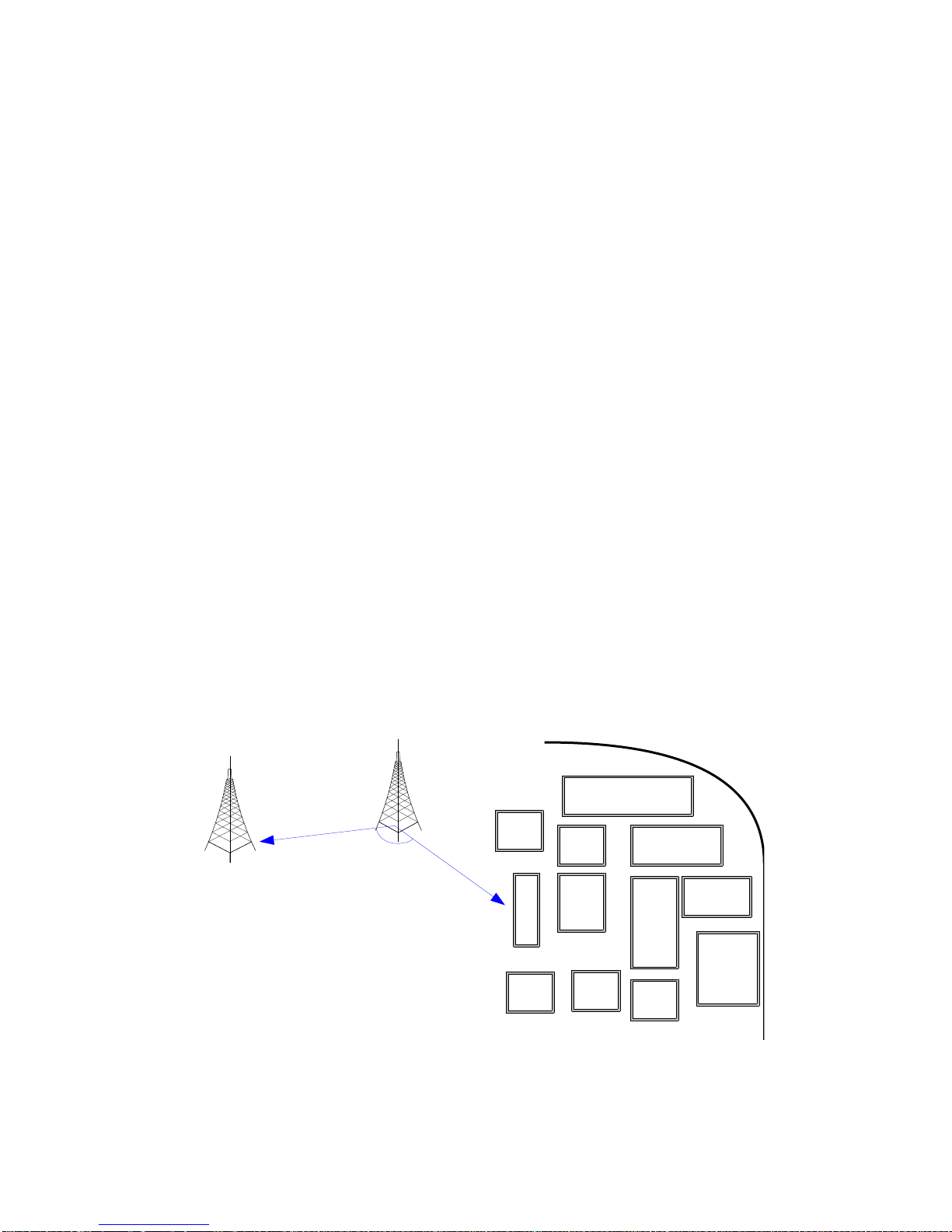
Figure 1 Outdoor Application
Above provides a typical installation layout of an outdoor project. The booster is connected via
coaxial cables to donor and service antennas. The donor antenna is placed on one side of the
mountain, pointing to the donor BTS to receive the signals. The service antenna is placed on
the other side, pointing to the coverage area to make the coverage. By taking advantage of the
mountain between them, the isolation requirement can be met. Mobile signals may then
transmit via the service antenna, booster and donor antenna to the donor BTS

Figure 2: Indoor Application
Above is the example of booster’s indoor application. The Yagi antenna is used as donor
antenna, which is placed outside of the building where it has easy access to the donor BTS.
Signals from the donor BTS are then introduced into the booster. After amplifying by the
booster, signals are divided into several parts by splitters and sent to the service antennas.
The service antennas are placed inside the building where it can extend radio coverage to the
dead zones. By the same way, mobile signals are sent back to the BTS.
2.3 Basic Booster System Components
Splitters
Splitters are isolated dividers that split or combine RF power. According to the
coverage requirement, splitter can distribute RF power into several paths to
achieve coverage of each area. In the meantime, mobile signals from different
coverage areas are combined together and transmitted into the booster. Here
we recommend some famous brand that with good quality. Andrew brand from
Commscope(www.commscope.com), model number: S-2-CPUSE-L-Ni or
S-2-TCPUSE-H-D (2-way splitter), S-3-CPUSE-H-Di6 or S-3-CPUSE-L-Ni
(3-way splitter); or the brand from TATFOOK(www.tatfook.com).
Antennas
Donor Antenna
Directional donor antenna, one for each booster, is recommended to improve
signal strength. Here for the industrial outdoor booster, the directional big panel
antenna is highly recommend.

Service Antenna
For outdoor coverage, the service antenna must be directional antenna whose
half-power beam width is depending on coverage requirements. For indoor
coverage, the omni-directional antenna can also be used in some condition.
Coaxial Cables
1/2” and 7/8” coaxial cables (50Ω impedance) are recommended to use with
the booster. These coaxial cables have low attenuation properties and are
ideal for longer cable run installations. There is a professional manufacturer in
USA Commscope (www.commscope.com), Andrew brand: model number:
FSJ4-50B, AVA5-50FX or AVA5RK-50FX are highly recommended. There is
another manufacturer with similar product, Kingsignal (www.kingsignal.cn),
Jumper Cables
Jumper cables have the flexible characteristic and they provide an easy way
to connect antennas, splitters and boosters to coaxial cables. Jump cables are
just the same materials as coaxial cable with short length, which is used for
adding the other passive components, such as splitters or couplers.
Warning: There are also many other brand or similar items, if clients
need to change such items, please compare the specifications carefully
and consult the professional manufacturer if it’s suitable to use the
other brand. The usage of the unqualified antennas, cables or coupling
device may result in the improper work of boosters and even damage
the device. Please double check before changing these items.
2.4 Advantages of Booster
Optimization
During BTS coverage optimization, full coverage cannot always be achieved
because of shadowing and blind spots. If optimization is carried out by simply
adjusting antenna direction or height, the process can be tedious and a long
process of trial and error until the required coverage is achieved. The process
can be time consuming and most times indoor coverage are not achieved. With
boosters, separate optimization is carried out while the whole interrelated
parameters between systems remain unaffected.
Same Service Quality with Low investment
When coverage needs to be extended or optimized, installing a new BTS or
micro cell may not be always the best solution and economical. In most cases
a booster will be the best solution that will provide the same service quality at
a relatively lower cost.

Fast & easy Installation
Compared to the Base Station, wireless boosters is space saving and does not
need additional wiring. Its installation simplicity and operational user friendliness
appeal greatly to many operators for the purpose of rural coverage or use of
temporary coverage during network optimization.
2.5 Block Diagram
The booster has two similar circuits, which are designed for uplink and
downlink respectively. Each circuit consists of three main modules, the Low
Noise Amplifier (LNA), the Frequency Converter (FC), and the Power
Amplifier (PA).
Let’s just consider the downlink part first, which is from BTS to MS. Please note
that uplink works in the same way except the signal direction is from MS to BTS.
Figure 4 illustrates the self-explanatory signal path after entering into the
booster.
Figure 4 Dual Band Selective Booster
When uplink or downlink signal enters the booster, it is filtered by duplexer
firstly. Then the filtered signal enters into LNA in which weak signals are
amplified with low noise figure. Then the signal passes FC where signal
frequency is made to IF to have a good filtration after passing through SAW
filter in the FC. Through module FC, operator’s signals are selected while the
competitors’ signals are strongly rejected. At last the signals are amplified in
power amplifier (PA) and are sent to service antenna.

2.6Outline of Available Functions
Local Control
This function is used when commissioning or checking booster status on site.
Booster is connected to a Laptop using the RS-232 cable. Operators can
configure, check parameters such as gain, alarm parameters etc. Refer to OMT
User’s Manual for more details about connection and OMT operation
procedures.
Remote Monitoring
Through the wireless modem, all functions that are accessible on the local end
can also be accessed from maintenance center remotely. Alarm signals are
constantly reported to maintenance center for constant tracking of the overall
system. Refer to OMT User’s Manual for more details about connection and
OMT operation procedure.
MCB
The booster is equipped with MCB (monitor and control board), which displays
booster operating and various alarm status. At the mean time, the UL and DL
attenuation can be adjusted to make booster to perform its best via the switch
on this board
Detailed alarm of the booster can be viewed on the front panel, please refer to
Section 5: Maintenance for in-depth details of each individual alarm condition
and their solution.
31dB Manual Gain Control
During installation, please attenuate the booster’s DL & UL gain (using the OMT
software or via the switch on MCB), taking into account the path loss value and
isolation issue to avoid interference towards the BTS and to optimize coverage
region.
31dB AGC
The 31dB AGC is used to maintain steady output power even when the
source signal fluctuates. It also can be used as an index to evaluate the
amplifier. This function effectively prevents the equipment from entering into
saturated state and thereby avoids signal distortion and call drops in the
coverage area.
3. Installation
3.1 Preparation
a. Ensure the power to be accessed is within the booster’s working range:
AC 90V~300V. A separate circuit breaker is recommended.
b. Ensure there’s sufficient isolation between the donor and service
antennas.
c. Ensure there are adequate resources to handle the weight of the
booster.
d. It’s recommended to prepare some jumper cables.
e. Booster used for outdoor installation is water resistant, but it is possible
that the booster’s performance may be influenced by weather factors
such as temperature and humidity. It is suggested to install the booster
in an indoor location with good draught. If the booster needs to be
installed outdoor, ensure that there is good draught and will not face
direct sunlight and in a location that stays within - 25℃to 55℃.
Recommended tools list
Table below lists the recommended tools that will be required for a successful
installation:
Item
Quantity
Item
Quantity
Signal Generator
1
Spectrum Analyzer
1
Test Mobile
1
Laptop
1
50 Ω load (terminator)
2
Electrical Drill
1
Multimeter
1
Spanner
2
Hammer
1
Screwdriver
1
Waterproof glue
1
Safety belt
1
RF arrestor (optional)
1
Other accessories
3.2 Antenna Installation
Selection of the correct antennas is one of the most important aspects for a
successful installation of a booster system. Installation location and
performance/characteristic of the antenna can strongly influence the Rxlev and
RxQual of the intended coverage area.
Rxlev. and RxQual are two important parameters, which describe the power
level and the quality of the GSM signal. Both parameters can be measured
using a testing mobile such as TEMS®.

The antennas are usually selected and purchased by the customer.
Manufacturer will provide recommendations for the most suitable types of
antennas based on our experience for a successful and trouble free installation
of the booster if required.
3.2.1 Donor Antenna
3.2.1.1 Donor Antenna Selection
There are many types of antennas on the market, but the following general
characteristics should be met during selecting the donor antenna, we will also
list some of the popular brand for your option in below:
1. Working frequency: The donor antenna needs to be compatible with the
booster’s operating frequency range.
2. Directivity characteristic: An antenna with good directivity is
recommended, it is essential for the booster to introduce a clean donor
signal to amplify.
3. Waterproof: The donor antenna needs to be waterproof to prevent
rainwater from affecting the antenna’s characteristics, ultimately affecting
the performance of the booster.
4. For outdoor booster, antenna’s front to back ratio must be higher than
20dB to assure excellent isolation on the site.
5. Recommended donor antennas: Argus brand from Commscope
(www.commscope.com): CNNPX306R-6P (16dBi gain) or
CNNPX308M-4P (17dBi gain). While for a safe working conditions of the
booster, please don’t choose any antennas that over 19dBi gain. There
are also other related items from Kenbotong (www.kenbotong.com) or
Tongyu Communication Inc. (www.tycc.cn).
3.2.1.1 Donor Antenna Installation
Donor antenna is to be installed at the location where excellent signals from
donor BTS can be received. When installing the donor antenna, the following
conditions need to be considered:
1. The antenna is recommended to be installed where donor BTS is in line
of sight. The signal level at the BTS port of the booster is recommended
to be in the range from -60dBm to -40dBm with an RxQual index ranging
from 0 to 2. The Rxlev of the primary BCCH is at least 6dB higher than
the BCCH of neighboring BTS sites.

2. When installing the donor antenna in a relatively high location, lightning
arrestor is necessary. Grounding of the arrestor and the antenna are
essential.
3. Waterproof of donor antenna’s connector with sealant is highly
recommended.
4. For outdoor project, the antenna needs to be positioned in an area
between the donor BTS and the coverage area, pointing to the donor
BTS to get an excellent donor signal.
5. For indoor project, usually the donor antenna is installed against the wall
of the building pointing towards the donor BTS. It should be installed at
least 3 meters above the ground to avoid shadowing when objects pass
in the front of the donor antenna. Also install the donor antenna higher
than the 7th floor is not recommended. When the antenna is located in a
high floor, it will be difficult to obtain a signal with good RxQ due to the
interference of signals from various nearby BTSs.
3.2.2 Service Antenna
3.2.2.1 Service Antenna Selection
The service antenna is usually selected and purchased by the customer, we will also
list some of the popular brand for your option in below. It needs to meet the
requirements below:
1. Working frequency: The service antenna needs to be compatible with the
booster’s operating frequency range.
2. Half-power Beam width: Select the antenna with suitable half-power beam
width according to the coverage area.
3. For outdoor coverage, the service antenna needs to meet two conditions
below: Waterproof and excellent Front-to-back Ratio. The antenna needs
to be waterproof to prevent rainwater from affecting the antenna’s
characteristics, ultimately affecting the performance of the booster. At the
meantime, the front to back ratio needs to be bigger than 20dB to assure
enough isolation of the site.
4. For indoor coverage, a broadband antenna, which can support the
frequency range of 824~2200MHz, are selected to be compatible to all
systems.
5. Recommended service antennas:
The maximum gain of the service antenna should no more than 7dBi. Here
are some of the brand that used for indoor coverage antenna: Andrew brand
from Commscope (www.commscope.com): CJLPA401U-W1 (7dBi gain) or
CLNA001U-CN2 (3 dBi gain); Kenbotong band (www.kenbotong.com):
TDJ-0825BKM-L (7dBi) or TQJ-0825XTS1 (3dBi).
3.2.2.2 Service Antenna Installation
It is necessary to find a good location for the service antenna in order to achieve
best coverage.
For indoor coverage, the following conditions need to be considered:
1. Avoid installing near metal or obstacles that may influence its coverage
performance.
2. Install the antenna at least 2m above the floor for the best coverage and for
the convenience of passers-by.
3. The service antenna should not be installed close to the donor antenna to
avoid isolation issues.
For outdoor coverage, the following conditions need to be considered:
1. Avoid installing near trees or other obstacles that may influence its
coverage performance.
2. The service antenna should not be installed too close to the donor
antenna to avoid issues with isolation. The angle between donor antenna
direction and service direction needs to be larger than 90 degrees. The best
condition is when the donor and the service antennas are installed in
opposite directions.
Repeater is installed
on this tower
Donor BTS
Coverage Area
DonorAntenna
Direction
ServiceAntenna
Direction
Thisangelmustbe
biggerthan90°
Figure 5
3. When installing the service antenna in a relatively high location, lightning
arrestors are necessary. Grounding of arrestor and antenna is essential.
4. Waterproofing of service antenna’s connector with sealant is highly
recommended.
3.2.3 Isolation
Isolation is an important concept when it comes to the implementation of a
booster system, especially for the outdoor project. There must be sufficient
isolation within the booster system, which means there must be enough distance
and obstacles between the donor and the service antennas, and their directions
are recommended to be in opposite directions. The propagation loss between
the antennas needs to be at least 15dB above the gain value used by the
booster. Non-compliance to this criterion can result in poor signal to the
coverage area and may damage the PA of the booster.
3.2.3.1 Self-oscillation Concept
Isolation is the propagation loss value from the booster’s output port to its input port.
For a wireless booster, insufficient isolation between donor and service antennas
will result in self-oscillation.
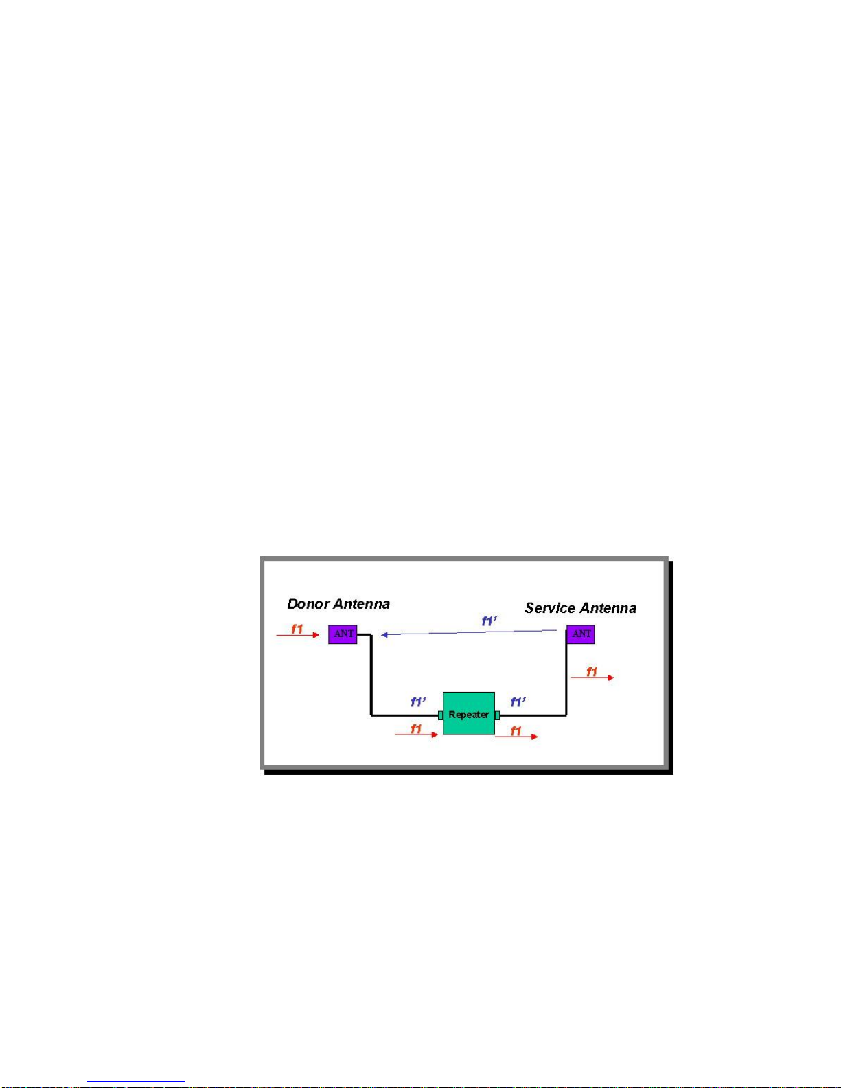
Figure 6
As shown in the above diagram, the donor antenna receives a RF signal f1 from the
Donor BTS, after amplification by the booster with a gain G, the signal radiates out
via the service antenna. Part of f1 (f1’) radiates back towards the donor antenna
(due to side lobe characteristics of antennas) and is picked up by the donor antenna
again and goes through the amplification process again. Severe self-oscillation
issue result in poor signal qualityand at times itcan damage the boosters’ amplifiers.
To prevent self-oscillation from occurring, the isolation value must be at least 15dB

above the booster gain.
When self-oscillation occurs, the alarm LED, “AGC Alarm” will be flashing. Booster
may be damaged if it operates under self-oscillation condition.
3.2.3.2 Obtaining the Isolation Value
Theoretical calculation (for reference only)
The physical isolation between the donor and the service antennas can be
theoretically estimated using the following formulas.
I = Isolation
D = Distance between donor and service antennas (m)
λ= Wavelength (m)
Gd= Gain of donor antenna facing service antenna
Gs= Gain of service antenna facing donor antenna
If there is an obstacle (wall etc.) between donor and service antenna, the
attenuation value of the obstacle need be added into the equation.
Physical Test
To obtain an accurate and more precise estimation of the isolation value, a
physical measurement may be carried out to obtain the isolation value for the
actually environment where the booster is installed. The measurement
procedures are:
Connect a signal generator to the donor antenna cable as illustrated
below and transmit a known frequency and power level from the signal
generator. Frequency needs to be within the idle frequency between the
uplink and the downlink frequencies.
For example, in GSM 900 system, uplink is 890~915MHz and downlink is
935~960MHz. We can use the frequency 920MHz, which is within
915MHz and 935MHz, to do the measurement. In DCS 1800 system, the
uplink is from 1710~1785MHz and the downlink is from 1805~1880MHz.
The idle frequency 1795MHz can be used to do the measurement.
Connect the service antenna to a spectrum analyzer and scan for the
known frequency.
Isolation ≥ Gain of Booster + 15dB
Vertical Isolation: I (dB) = 28 + 40 log (D/λ)
Horizontal Isolation: I (dB) = 22 + 20 log (D/λ) – (Gd+ Gs)

Make a record of the power level from the spectrum analyzer.
Subtract the power level received at the spectrum analyzer from the
power level of the signal generator to obtain the isolation value..
Figure 7
A relatively strong transmitting power from the signal generator is
recommended (excess of 25dBm) for easy recognition and detection by the
spectrum analyzer.
For example, signal generator sends out a signal 1795MHz with 25dBm power
level.
The signal scanned by the spectrum analyzer = –70dBm.
So, Isolation = 25dBm - (-70dBm) = 95dB
In this condition, to avoid self-oscillation, the gain of booster must be set to be
no more than 80dB, which is 15dB lower than the isolation value.
3.3 Booster
3.3.1 Installing the Booster
3.3.1.1 Wall Mount Installation
There are 2 steps of installing the booster. Mounting the bracket on the booster with screws:
See the below in figure 8.
Isolation (dB) = Output Power from Signal Generator –Received Power at the
Spectrum Analyzer

Figure 8
Drill 4 holes in the wall for hanging the bracket that hold the booster:
Figure 9

After that you will see the final pictures after installation.
Figure 10
4. Commissioning
The following chapter outlines the process to optimize the performance of the
booster. The gain setting, isolation, downlink output power, and booster uplink
noise contribution will be considered
4.1 Commissioning Principle
4.1.1 Downlink Output Power
The total downlink output power of the booster is depending on the input power
and the booster gain. To ensure the maximum power of the booster is achieved
at the MS port of the booster, the following condition should be met.
4.1.1.1 Gain and Output Power
The gain is the amplifying ability of the booster. The booster has a constant gain
for both uplink and downlink. Both uplink and downlink gain can be adjusted by
setting attenuation values.
DL Gain = Min {(DL Required Output Power - Input Power), Maximum DL Gain}

The maximum output power of the booster is determined by the linearity of the
amplifier block of the booster. For any given input signal power, its
corresponding output is increased by the gain of the booster, the output power
will increase along a linear curve based on the fixed gain value.
If the input signal amplified by the gain set exceeds the rated maximum output,
the AGC (automatic gain control) function will be triggered. The AGC ensures
that the maximum output power of booster is maintained and does not overdrive
the booster’s amplification circuit. Figure 15 demonstrates the relation between
the output power and the gain.
Figure 11
Suppose maximum output power of booster is 37dBm and its gain is 89dB:
So, when input power is weaker than –52dBm, output power = Input Power +
89dB
When input power is stronger than -52dBm, output power = 37dBm
4.1.1.2 Link Budget
Below provides a typical process for calculating the link budget of the booster
system. Note that gain is 89dB in the picture below.

Figure 12
4.1.2 Isolation
Isolation is an important condition that MUST be met for trouble free operation of
the booster. To ensure the booster’s working properly, the following equation
MUST be met.
Refer to Section 3.2.3 Isolation for further details about isolation and how to
measure the value.
5. Maintenance
The proceeding section outlines the definition of the alarm conditions on the
front panel and OMT, and the steps that can be used to rectify or clear the
alarms.
5.1 Alarms and Solutions
When an alarm is triggered, its corresponding LED will change to be red and displayed on the
front panel.
The following table lists the different alarms and possible solutions to correct the fault.
Booster Gain ≤ Isolation – 15dB
Table of contents


