Signet 3350 User manual

Signet 3350/3550 Ultrasonic Flowmeter
3-3350.090 Rev. A 11/05 English
3-3350.090
1. Description
The Signet 3350/3550 Ultrasonic Flowmeter uses transit-time technology to deliver
accurate flow rate and totalizer information with no direct fluid contact.
Originally used for temporary installations and periodic flow rate validation, today these
ruggedized instruments are perfectly suited to applications where pipes cannot be
penetrated, or where the fluid medium is hazardous or easily contaminated.
The clamp-on sensors are easy to install, without interrupting the process stream. Simply
enter the pipe parameters and the application preferences; the 3550 will provide stable and accurate data that is tailored
by you, for your unique requirements.
The Ultrasonic Flowmeter is programmable via the front panel keypad. Select display menu instructions in English,
French, Spanish, German or Japanese on a 2-line, backlit LCD.
ENT
ESC
Signet Ultrasonic Flowmeter
123.456 GPM
12345678 Gal
Caution: High Voltage
Turn off power before opening unit
Contents Page
Description Front cover
Specifications 2
Features and Functions 3
Installation and Quick Start Guide 4
Pipe Parameters 8
Factory settings 12
Parameter Protection 14
Measure setup mode 15
Configuring the Display 17
Set the 4-20 mA Range (FLOW SPAN-1) 17
Set Dual 4-20 mA Ranges (FLOW SPAN-2) 18
Set Pulse Output and Totalizer functions 19
Start, Stop and Reset the Totalizer 20
Set Relay Outputs (DO1 and DO2) 21
Adjust the 4-20 mA Span 22
Calibrate the 4-20 mA Output 23
Set Serial Communication parameters 25
TROUBLESHOOTING AND MAINTENANCE 27
Piping data: Acoustic Velocity in Solids 33
Acoustic Velocity of Water (Listed at varying temperatures) 33
Acoustic Velocity in Fluids 34
Pipe Dimensions: PVC 41
Pipe Dimensions: Steel 43
Pipe Dimensions: Welded Steel, Aluminum, and Copper 44
Pipe Dimensions: Galvanized Steel Tubing and Pipe 45
Pipe Dimensions: Iron 47
Ordering Information Back Cover

2
Scaled for footer
Signet 3350/3550 Ultrasonic Flowmeter
General
Flow rate range: 0.3 to 10 m/s (1 to 33 ft/s)
Low flow cut off : 0 to 5 m/s configurable
Suitable pipe materials:
• Plastic (PVC, PVDF, CPVC, PP, PE, PEEK, etc.)
• Metals (carbon steel, SS, copper, aluminum, iron)
Pipe Size Range
• Plastic pipes:
• 3550-100: DN25 to DN100 (1 in. to 4 in.)
• 3550-200: DN50 to DN225 (2 in. to 9 in.)
• Metal pipes:
• 3550-100: DN50 to DN100 (2 in. to 4 in.)
• 3550-200: DN50 to DN225 (2 in. to 9 in.)
Application: Clean liquids, no aeration or particles
Accuracy
Pipe size Over 2 m/s
(6 ft/s)
Under 2 m/s
(6 ft/s)
DN25 to DN40
(1 to 1½ in.)
±3% of rate ±0.06 m/s
DN50 to DN225
(2 to 9 in.)
±2% of rate ±0.04 m/s
Display: LCD w/back light 2x16 characters
• Sensor signal quality LED - Normal: green, Error: red
• User selectable language:
English, French, German, Spanish, Japanese
Display resolution:
• Flow rate: 00.0000 min to 9999999 max
• Totalizer: 00000.00 min to 99999999 max
Totalizer Error condition:
Hold last good value or Continue Count
Error Time delay 0 to 100 s
Damping: 0 to 100s Averaging function for 4 to 20 mA
output and Flow Rate display
Response time: 200 ms
Material
Flowmeter: ABS
Sensors: PBT
Sensor frame: 304 SS
Electrical
• 3-3350-1: 100-120 VAC ±10%, 50/60Hz, 15VA max
• 3-3350-2: 200-240 VAC ±10%, 50/60Hz, 15VA max
Signal cable: RF coaxial cable, 5 m std (Avail to 30 m)
Output Specifications
4 to 20 mA output
• Max. load resistance: 600Ω
4 to 20 mA Error condition (Burnout): User selectable
• Hold last good value • Over-scale (22.6 mA)
• Under-scale (3.8 mA) • Zero (4 mA)
Bi-directional or Autoscale dual ranges
• User Selectable
• Hysteresis: 0 to 10% of flow rate range
• Flow range applicable to digital output
Output Specifications (continued)
Relay output (DO2)
• Capacity: 220V AC /30V DC, 1A (resistive load)
• Mechanical SPDT relay contact: (replaceable)
• Mechanical life expectancy: > 2 x 10⁷ operations
• Relay Pulse width: User selectable 50, 100 or 200 ms
Open collector output (DO1)
• Capacity: 30V DC, 0.1A
• Total pulse: Programmable, 1 pps to 1 pulse per day
• Open Collector Pulse width:
User selectable 5, 10, 50, 100 or 200 ms
Digital output Logic
ACTIVE ON: Relay DO2 Normally OFF (de-energized)
Open Collector DO1 normally open
ACTIVE OFF: Relay DO2 Normally ON (de-energized)
Open Collector DO1 normally closed
Programmable functions
• Cutoff limit (common to DO1 and DO2)
• NOT USED
• TOTAL SWITCH Operation
• +TOTAL PULSE: Proportional to +Flow rate
• –TOTAL PULSE: Proportional to -Flow rate
• FLOW SPAN-2:
Select a contact output at SPAN-2 measurement status
(forward automatic 2 ranges, forward/reverse automatic
2 ranges).
• ALARM Operation
- HARDWARE: Contact output at EEPROM error.
- PROCESS: Contact output when signal is bad
FLOW SWITCH Operation
• UPPER SWITCH: HIGH Flow Alarm
• LOWER SWITCH: LOW Flow Alarm
• TOTAL SWITCH: Volumetric Pulse
Flow requirements
• Well-developed turbulent or laminar flow
• Maximum air in liquid volume:
0.2% @ 1 m/s (inversely proportional to velocity)
Weight
• Flowmeter: 0.8 kg
• Sensor: 3-3550-100: 0.3 kg
3-3550-200: 0.4 kg
Environmental
NEMA4/IP65 enclosure for both flowmeter and flow sensor
Process temperature:
• With silicone rubber acoustic couplant
-40°C to +180°C (-40°F to 356°F)
• With silicone-free grease acoustic couplant
0°C to 60°C (32°F to 140°F)
Ambient temperature:
• 3-3350-X: -20° to 50°C (-4° to 122°F)
• 3-3550-XXX: -20° to 60°C (-4° to 140°F)
Short-term thermal stability: 140ºC, 30 min
Relative Humidity: 90% (non-condensing)
Specifications

3
Scaled for footer
Signet 3350/3550 Ultrasonic Flowmeter
Features and Functions
Signet Ultrasonic Flowmeter
2
1
5
4
3
8
6
7
14
9
11 10
15
12
13
No. Name Description
1. Cable ports, PG 13.5 For power cable, Output Cable
2. Cable ports, PG 9 For signal cables only
3. Flow signal LED Green = Normal operation, Red = Error condition
4. Escape key Moves back one menu level or cancels changes not yet ENTERED
5. UP key Selects items, scrolls active numeric values and symbols
6. Shift key Advances blinking cursor, selects decimal position
7. Enter key ENTERS (saves to memory) new settings and selections
8. Liquid Crystal Display Displays flow rate and menu information
9. Power terminals Connect AC or DC power
10. Input/Output Cables Sensor coaxial cables, Relay output and 4-20 mA output cables
11. Fuse and Fuse holder 250 V, 0.5 A for AC models, or 250 V, 1 A for DC models
12. Communication board terminals Wiring for optional Comm board for serial data output
13. Communication board RS-232 (3-3350.403) or RS-485 (3-3350.404) Optional
14. Arrester board Optional arc supressors for relay outputs
15. Relay DO2 Dry Contact, 1 A 220 VAC or 30 VDC resistive load
16. Scale Used to measure proper spacing for TX-RX sensors
17. Locking hole Sensors lock in place at these openings
18. Transmit and Receive Signal Cables BLACK = Downstream, RED = Upstream
19. Sensor Frame Mounting apparatus for Sensor units
20. Sensors Ultrasonic TX-RX sensors
21. Mounting straps for Frame Stainless steel belts (3-3550.393)
22. Spring tightener Removes slack from steel mounting straps after mounting
Spacing illustrated: 34
19
17
16
18 & 20
18 & 20
21 &22

4
Scaled for footer
Signet 3350/3550 Ultrasonic Flowmeter
Installation and Quick Start Guide
The electronics may be mounted on a wall or on a pipe
stand.
• For wall mounting, use two M8 bolts. Drill holes based
on the dimensions illustrated here.
• For pipe mounting, use the two U-bolts supplied with
the unit.
Mounting hole
130 mm (5.1 in.)
70 mm (2.75 in.)
140 mm (5.5 in.)
170 mm (6.7 in.)
197 mm (7.75 in.)
Mounting
plate
1. Select a mounting location and method for the 3350 electronics.
The installation and startup of this flowmeter is divided into
seven steps. They are organized in the sequence they
should be completed:
1. Select a mounting location and method for the 3350
electronics.
2. Select a location and mount the 3550 strap-on sensor
assembly onto the pipe.
3. Connect the sensor cables and 24 VDC power to the
electronics terminals.
4. Navigate to the MEASURE SETUP menu and enter
the information for your pipe and fluid.
5. Position the two ultrasonic transducers at the spacing
indicated by the PIPE PARAMETER and secure them
in the frame.
6. Review the system troubleshooting information and the
initial values of the output parameters in this manual to
determine if it is safe to start the flowmater.
7. Program the 3350 flowmeter electronics to reflect the
remaining application requirements.
ENT
ESC
Signet Ultrasonic Flowmeter
123.456 GPM
12345678 Gal
Caution: High Voltage
Turn off power before opening unit
5
Scaled for footer
Signet 3350/3550 Ultrasonic Flowmeter
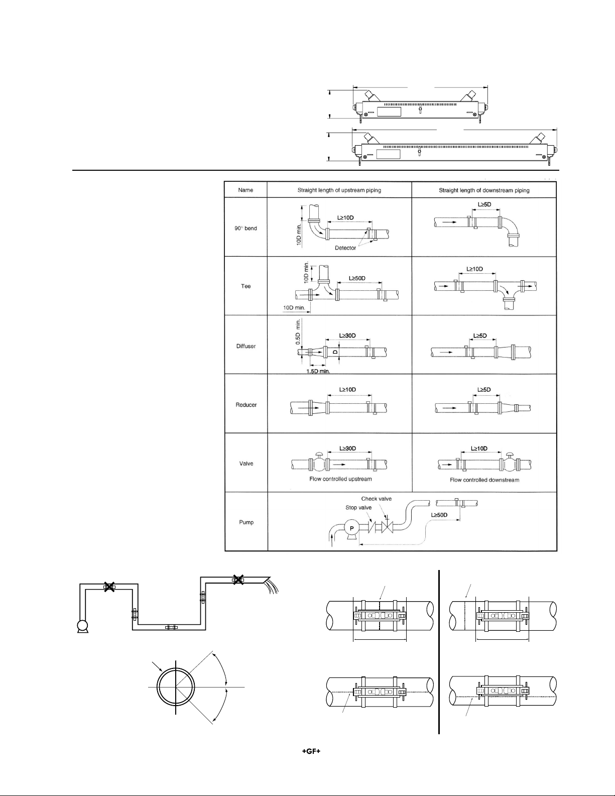
Air tends to accumulate May not completely be filled with liquid
May not
completely be
filled with liquid Good
Good
Pump
The length of upstream and downstream straight pipe of
the ultrasonic detector should be long enough to ensure
accurate measurements.
2A. Select a location for the 3550 strap-on sensor assembly.
The sensor can be installed at any
position around the pipe when
attention is given to the following
requirements:
• The pipe must be completely
filled with fluid.
• IOn horizontal pipes, mount
the sensors at ±45° from the
horizontal plane to avoid air
pockets and debris that may
accumulate at the top and
bottom of the pipe.
• The pipe surface must be free
of pits and distortions. Use
thinner, sandpaper, etc., to
remove and surface corrosive,
rust, etc, and to remove any
rust, pitch, or other materials
from the pipe surface.
• Do not mount the sensors on a
section of pipe that is visibly out-
of-round, or straddling a flange
or weld seam.
Pipe
Horizontal
45°
45°
Weld seam Weld seam
Sensor straddles weld seam Sensor is clear of weld seam
Sensor is clear of weld seam.
Sensor is on top of weld seam
No Yes
50.8 mm
(2.0 in.)
240 mm
(9.45 in.)
3-3550.100
50.8 mm
(2.0 in.)
360.6 mm
(14.2 in.)
3-3550.200
6
Scaled for footer
Signet 3350/3550 Ultrasonic Flowmeter
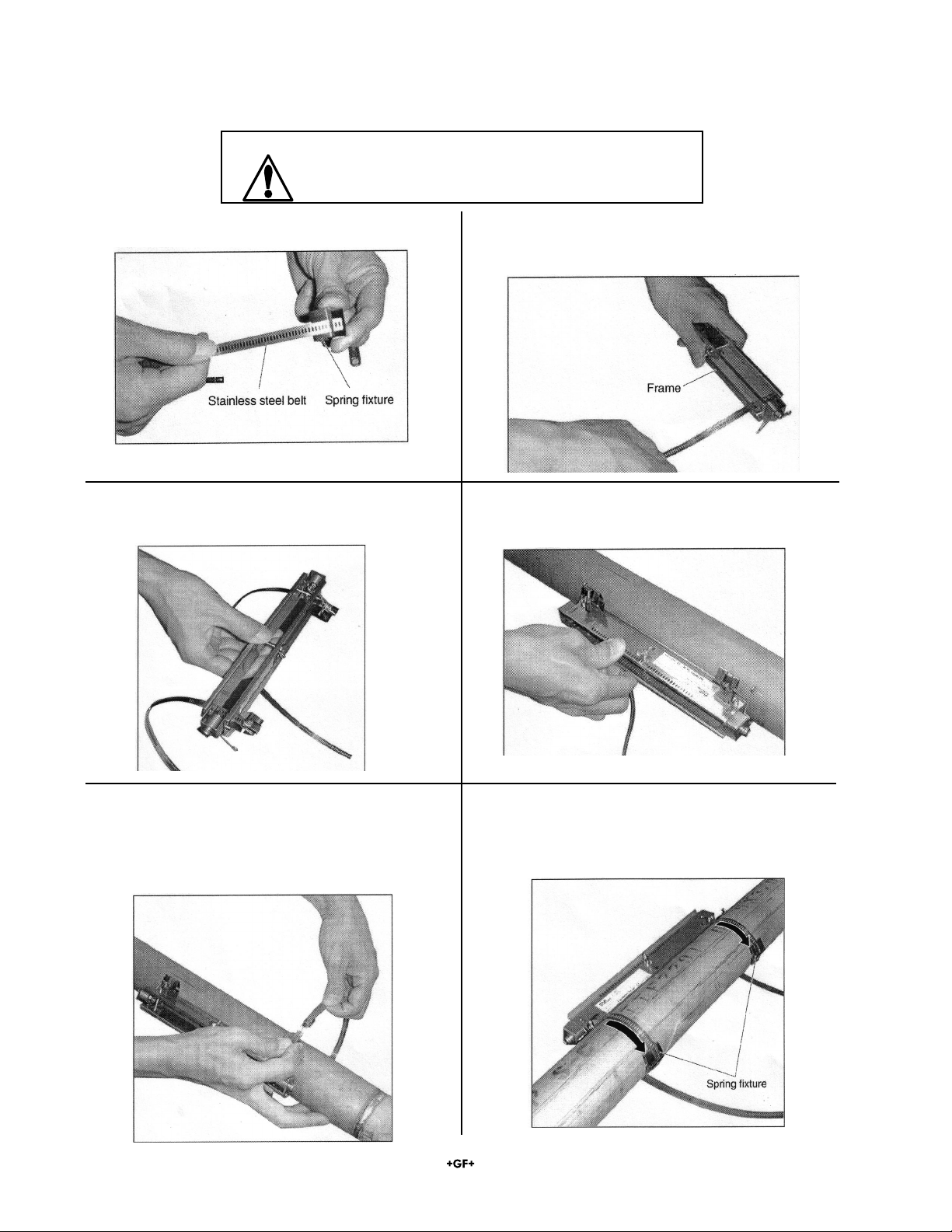
3. Place the frame on a pipe smooth, clean section sub-
jected to a surface treatment.
4. Temporarily tighten the first stainless steel belt on the
pipe.
5. Adjust the frame so it is parallel with the pipe, put the
spring fixture to the side of the frame and tighten the
stainless steel belt so that the frame will tightly be fitted.
Mounting on pipe whose diameter is DN150 (6 in.) or
larger, connect 2 stainless steel belts.
6. After tightening both stainless steel belts, slide the
spring fixture to the opposite to the frame.
Note: Frame must be relocated, use new stainless steel
belts.
1. Slide the spring fixture onto the stainless steel belt. 2. Pass the stainless steel belt through 2 belt holes on the
frame.
Handle the steel mounting belts carefully to avoid injury.
2b. Mount the 3550 strap-on sensor assembly onto the pipe
WARNING! CAUTION

7
Scaled for footer
Signet 3350/3550 Ultrasonic Flowmeter
Connect the signal line with BNC connectors to the sensor
units. Engage the red BNC connector upstream, and the
black BNC connector downstream.
Before mounting the sensor unit into the frame, Apply
silicone (or silicone-free grease) over the transmission
surface of the sensor unit. Do not leave any bubbles.
When using silicon-free grease, do not exceed the fluid
temperature range:
• Silicon rubber: 20 to 100°C
• Silicon-free grease: 0 to 60°C
Silicon-free grease should be reapplied approximately once
every 6 months. (Silicon rubber need not be reapplied.)
Insert the sensor unit into the frame. The UPSTREAM and
DOWNSTREAM sensors must be spaced according to the
PIPE PARAMETER results. Do not lock the sensors yet.
They will need to be adjusted in step 5.
Mount both sensor units so as to be roughly symmetrical
with respect to the frame.
2b. Mount the 3550 strap-on sensor assembly onto the pipe (continued)
8
Scaled for footer
Signet 3350/3550 Ultrasonic Flowmeter
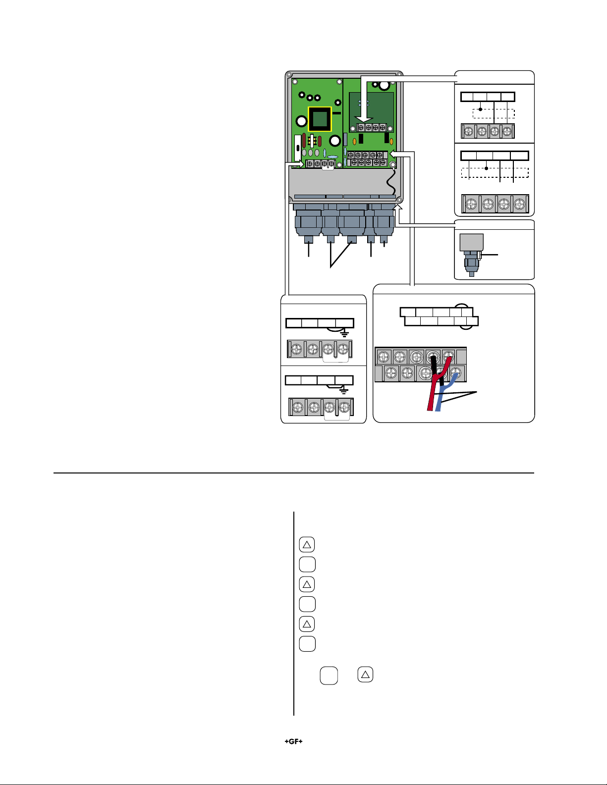
3. Wiring
Main Board Terminal Block
Power Board Terminal Block
Upstream
sensor cable
Downstream
sensor cable
Power cable
Output signal cable
(analog output, DO1, DO2,
communication synchronization)
AC power source: 100 to 120 or 200 to
240 V AC, 50/60 Hz
Notes:
1.All screws are M3 on the terminal block. Use crimp-style terminals for M3 whose outer diameter is
5.8 mm (¼ in.) or smaller.
2. Connect the power board ground terminal block or the external ground terminal to earth ground.
3. Use only cables supplied with sensors.
Red (upstream sensor)
Coaxial signal cables
DC power source: 20 to 30V DC
L N GND GND
GND GND
Communication Board
Terminal Block (Option)
External Ground Terminal
RS-232C
NC GND RXD TXD
RS-485 and synchronization
SYNC SHILD TXCR2 TXDR1
Synchronization
RS-485
Ground terminal
Iout(+) DO1(+) DO2(+) GND HF1
Iout(-) DO1(-) DO2(-) GND
Upstream sensor
Downstream sensor
HF2
+-
Blue (downstream sensor)
Connect the power source and the two sensor
cables as shown here.
4. PIPE PARAMETERS
Press: Display shows:
x 4 “MAINTENANCE MODE”.
ENT
“CURRENT CALIBRATION”.
x7 “LANGUAGE”.
ENT
2nd line begins blinking.
Scroll to the language required.
ENT
New selection is stored.
Use
ESC
and keys to resume measurement mode.
Display language
Before proceeding to the next step, the 3350 can be set to
display the menus in several languages. The procedure to
change from the ENGLISH selection is provided here.
The languages available are listed in the order in which
they appear in the menu.
• English
• Japanese
• German
• French
• Spanish

9
Scaled for footer
Signet 3350/3550 Ultrasonic Flowmeter
Press: Display shows:
3x. 1st line: “MEASURE SETUP”
ENT
1st line: “SYSTEM UNIT”
3x. 1st line: PIPE PARAMETER”
ENT
1st line: “OUTER DIAMETER”. 2nd line: “60.00 mm”
ENT
Cursor blinks on 2nd line.
and Input the outer diameter. (Pipe data is located in section 3.2.)
ENT
“COMPLETE” is indicated for about 1 second on 2nd line.
1st line: “PIPE MATERIAL”. 2nd line: “PVC” (As currently selected)
ENT
Cursor blinks on 2nd line.
Select the pipe material from menus. If the pipe material is not listed, select “PIPE SV” and
input the sound velocity of the pipe material at the end of its, See piping data in section 3.2.
ENT
“COMPLETE” is indicated for about 1 second on 2nd line.
1st line: “WALL THICKNESS”. 2nd line: “4.50mm” * (or as currently selected)
ENT
Cursor blinks on 2nd line.
and Input the wall thickness of a measurement pipe.See piping data in section 3.2.
ENT
“COMPLETE” is indicated for about 1 second on 2nd line.
The PIPE PARAMETER section of the Measure Setup menu calculates the correct spacing between the two Ultrasonic
electrodes. This must be done before the installation can be completed The following pages will guide the user through
each step.
If the parameter protection is set at “PROTECTION ON”, change it to “PROTECTION OFF”.
The ID NO. must be entered if it is active.
4. PIPE PARAMETER (continued)

10
Scaled for footer
Signet 3350/3550 Ultrasonic Flowmeter
Press: Display shows:
1st line: “LINING MATERIAL”. 2nd line: “NO LINING”
ENT
Cursor blinks on 2nd line.
Select the lining material. If the material is not listed, select “Lining S.V.” and input the sound
velocity of the lining material. Sound Velocity data is located in section 6.6.
ENT
“COMPLETE” is indicated for about 1 second on 2nd line.
1st line: “LINING THICKNESS”. 2nd line: “2.00 mm”. (Not present if “No Lining” is selected)
ENT
Cursor blinks on 2nd line.
and Input the lining thickness.
ENT
“COMPLETE” is indicated for about 1 second on 2nd line.
1st line: “KIND OF FLUID”. 2nd line: “WATER”.
ENT
Cursor blinks on 2nd line.
Select “WATER” or “SEA WATER”. If the fluid is not listed, input the sound velocity of fluid.
Sound Velocity (acoustic velocity) data is located at the back of this manual.
ENT
“COMPLETE” is indicated about 1 second on 2nd line.
1st line: “KINEMATIC VISCO”. 2nd line: “1.0038E-6m2/s”. Kinematic viscosity of water or Sea
Water is factory set. If fluid to be measured is other than water, input the kinematic viscosity
referring to piping data at the back of this manual.
ENT
Cursor blinks on 2nd line.
and Input the kinematic viscosity.
ENT
“COMPLETE” is indicated about 1 second on 2nd line.
First line: “SENSOR MOUNTING” Second line: “V”
(Do not change this setting. The “Z” option is not available for this system)
1st line: “SENSOR TYPE”. 2nd line: “3-3350-100”.
ENT
Cursor blinks on 2nd line.
Select “3-3350-100” or “3-3350-200”.
ENT
“**COMPLETE**” is indicated about 1 second on 2nd line.
ESC
1st line: “PIPE PARAMETER”. 2nd line: “S= 16 (48mm)”
Use this value to secure the two sensors at the correct spacing.
ESC
1st line: “MEASURE SETUP”
2x. Measurement mode is resumed.
4. PIPE PARAMETER (continued)

11
Scaled for footer
Signet 3350/3550 Ultrasonic Flowmeter
5. Position the two ultrasonic sensors at the spacing indicated by the PIPE PARAMETER
and secure them in the frame.
Spacing illustrated: 34
6. System Troubleshooting
If everything has been completed according to the instructions, the system is ready to begin working.
All of the remaining settings and menus enable the output functions to be tailored to suit a specific application. Review
the next two pages and identify the functions that must be modified for the application.
About 10 seconds after connecting the signal line, the red LED on the flow transmitter should turn green, indicating the
received signal is normal.
If the LED remains red, the Flowmeter is not receiving a good signal from the 3350 sensor.
The problem is most probably caused by the sensor installation.
Check these conditions:
Sensor spacing: Are the sensors the correct distance apart?
Sensor orientation: Are both sensors facing outward from each end of the frame?
Lock mechanism: Are both lock mechanisms securely latched into the frame?
Lubricant: Have the two sensors been coated liberally with silicone grease or a similar filler?
Parameter settings: Is the information in the PARAMETER SETTINGS menu correct?
Full pipe: Is the pipe filled with fluid?
Closeup of the center mark on the sensor and the spacing
scale on the frame.
12
Scaled for footer
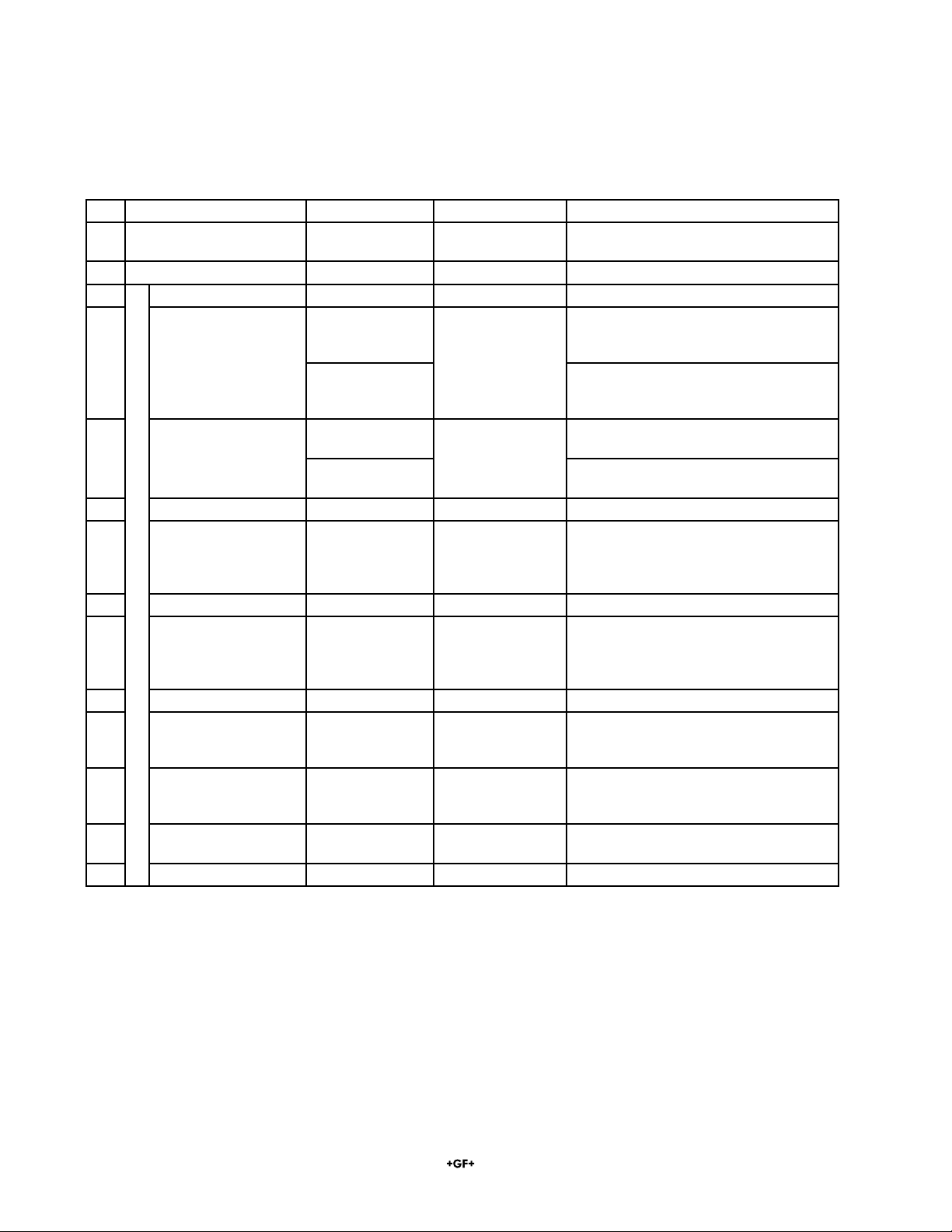
Signet 3350/3550 Ultrasonic Flowmeter
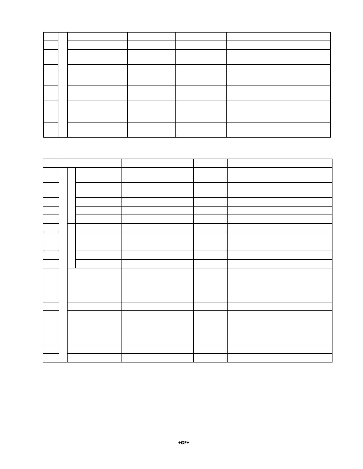
Factory settings
No. Setting Item Setting Range Initial Value Settable Value
1 Parameter protection 2 menus PROTECTION ON PROTECTION ON,
PROTECTION OFF
2 ID No. 0000 TO 9999 0000
3 Unit system 2 menus Metric Metric (metric system)
4 Flow rate unit 12 menus
(Menus system)
L/s l/s, L/min L/h ML/d m3/s m3/min
m3/h Mm3/d BBL/s BBL/min
BBL/h MBBL/d
12 menus
(Inch system)
gal/s gal/min gal/h Mgal/d ft3/s
ft3/min ft3/h Mft3/d BBL/s BBL/min
BBL/h MBBL/d
5 Total unit 8 menus
(Metric system)
mL mL L m3 km3 Mm3 mBBL BBL
kBBL
10 menus
(Inch system)
gal kgal ft3 kft3 Mft3 mBBL
BBL kBBL ACRE-in ACRE-ft
6 Pipe outer diameter 10.00 to 300mm 60.00mm [mm, in]
7 Pipe material 10 menus
Sound velocity;
1000
to 3700 m/s
PVC PVC, PVDF, PEEK, PP, CARBON
STEEL, STAINLESS STEEL, COPPER,
other (sound velocity:__[m/s, ft/s])
8 Wall thickness 0.1 to 50.00mm 4.50mm [mm,in]
9 Lining material 7 menus
Sound velocity:
1000
to 3700m/s
No lining No lining, tar epoxy, mortar, rubber,
Teflon, Pyrexglass, other (sound veloc-
ity:___[m/s, ft/s])
10 Lining thickness 0.01 to 50.00 [mm, in]
11 Fluid type 3 menus
Sound velocity:
500 to 2500m/s
Water Water, sea water, other (Sound velocity:
[m/s, ft/s])
12 Kinematic viscosity 0.0001 to
999.9999 x 10-
6m2/s
1.0038 x 10⁻⁶m2/s [x10-6m2/s, ft2/s]
13 Sensor mounting
method
2 menus V V,Z
14 Sensor type 2 menus 3-3350-100 3-3350-100, 3-3350-200
Measurement conditions
The tables below list each setting in the 3350 Magmeter menus, all of the available options, and the factory settings that
will be found in a new instrument.
13
Scaled for footer
Signet 3350/3550 Ultrasonic Flowmeter
No. Setting Item Settable Range Initial Value Settable Value
22 Flow span-1 0.3 to 10m/s in terms of flow
velocity
10.0000L/s Units are based on FLOW RATE UNIT.
23 Flow span-2 0.3 to 10m/s in terms of flow
velocity
0.0000L/s Units are based on FLOW RATE UNIT.
24 Hysteresis 0 to 10% 5.00% %
25 Burnout 4 menus Hold Hold, upper limit, lower limit, sero
26 Burnout timer 0 to 100sec 10sec sec
27 Total action 3 menus Start Start, stop, reset
28 Pulse value 0.00001 to 999999 1mL Units are based on TOTAL UNITS
29 Total pulse width 5 menus 5msec 5,10,50, 100, 200msec
30 Burnout 2 menus Hold Hold, count
31 Burnout timer 0 to 100sec 10sec sec
32 DO1 output type 5 output contents menus
3 alarm menus
Flow switch range 0 to 10
m/s. Total switch range:
0.00001 to 99999999
NOT USED NOT USED, Flow direction, Alarm [all,
hard, process], Flow switches, Upper limit,
Lower limit, Total switch.
(Units are based on FLOW RATE UNITS
and TOTAL UNITS selections.)
33 DO1 output action 2 menus ON, OFF
34 DO2 output type 5 output contents menus
3 alarm menus
Flow switch range 0 to 10
m/s. Total switch range:
0.00001 to 99999999
NOT USED NOT USED, Flow direction,Alarm [all,
hard, process],Flow switches, Upper limit,
Lower limit, Total switch
(Units are based on FLOW RATE UNITS
and TOTAL UNITS selections.)
35 DO output action 2 menus ON, OFF
36 Span calibration 0 to ±200% 100.0% %
Analog OutputTotal output
Output conditions
15 Zero adjustment 2 menus Clear (adjusted) Set zero, clear (factory set at clear)
16 Damping 0 to 100sec 5 sec sec
17 Low flow rate cut off 0 to 5 m/s in terms
of flow velocity
0.001 L/s Units are based on FLOW RATE UNIT.
18 Display 1st line con-
tents
7 menus Flow velocity (m/s) Flow velocity, flow rate (ACTUAL), flow
rate (%), forward total, reverse total, for-
ward total pulse, recerse total pulse
19 Display 1st line deci-
mal point position
00000.000 ���������
Mark the decimal position
20 Display 2nd line con-
tents
7 menus Flow rate (L/s) Flow velocity, flow rate (ACTUAL), flow
rate (%), forward total, reverse total, for-
ward total pulse, reverse total pulse
21 Display 2nd line deci-
mal point position
00000.000 ���������
Mark the decimal position
Output conditions
14
Scaled for footer
Signet 3350/3550 Ultrasonic Flowmeter
Parameter Protection
Parameter Protection serves to protect the flow meter settings from unauthorized changes.
• The 3350 uses an Identification number (ID No.) to enable authorized changes.
• The ID number is factory set at 0000 and the Parameter Protection is turned ON.
• To change the ID number, the parameter protection must first be turned OFF:
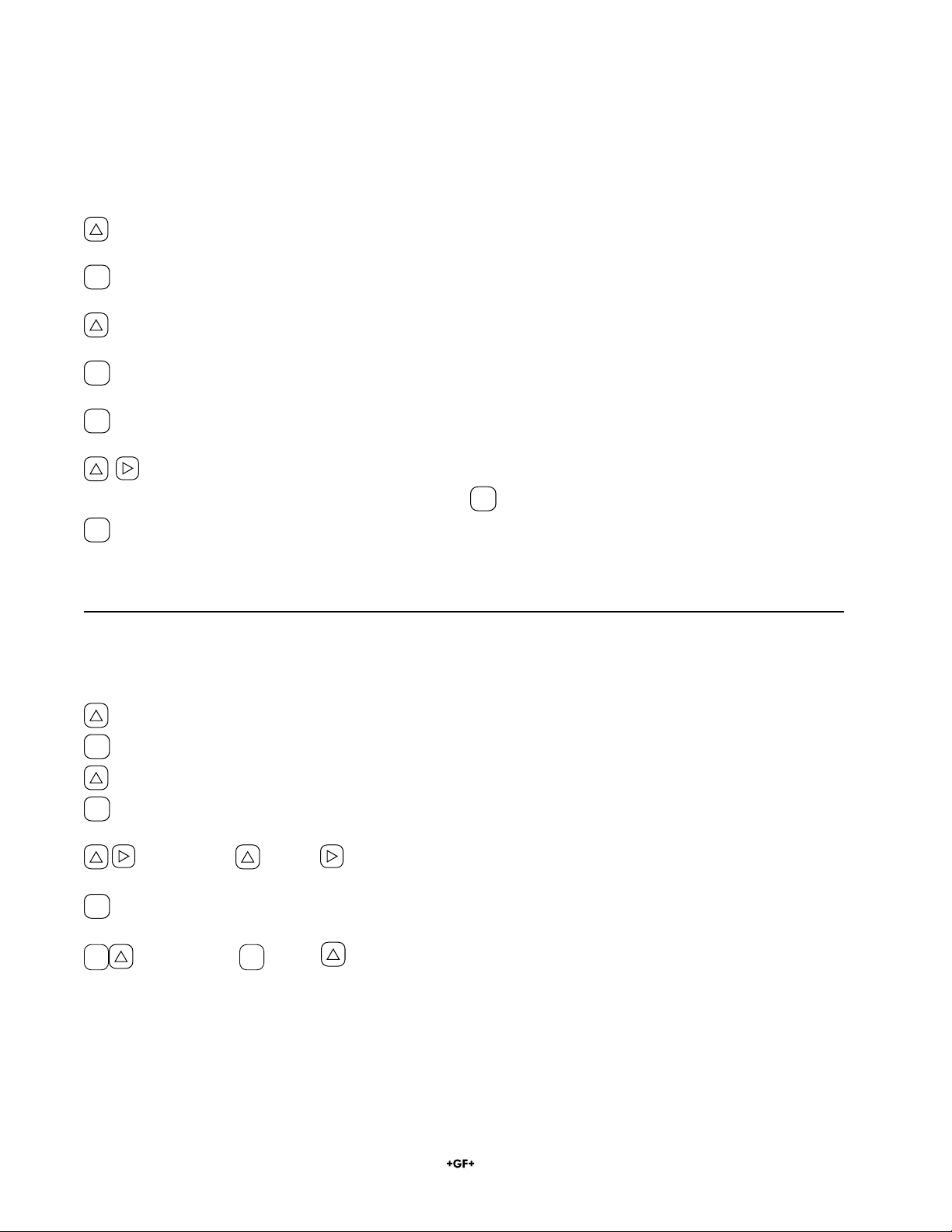
Press: Display shows:
First line: “PAR. PROTECTION” Second line: “PROTECTION ON”
ENT
2nd line of display begins blinking.
“PROTECTION OFF”.
ENT
“INPUT ID NO.”.
ENT
“0000” with first zero blinking.
Use UP and RIGHT buttons to set the ID No. into the display
Note: If ID No. is “0000” (factory set), press
ENT
key to set the parameter protection to OFF.
ENT
First line: “PAR. PROTECTION” Second line: “PROTECTION OFF”
* If “INPUT ERROR!” appears, the ID No. is incorrect. The display returns to the previous step.
Identification (ID) number
Press: Display shows:
4x “MAINTENANCE MODE”.
ENT
“CURRENT CALIBRATION”.
8x “REGISTER ID NO.”
ENT
2x 2nd line blinks
Press key and key to compose a new ID number.
ENT
“COMPLETE” is indicated about 1 second on 2nd line.
ESC
Using
ESC
key and key to resume the measurement mode.
Note: To enable the new ID number, set the parameter protection to “PROTECTION ON”.
15
Scaled for footer
Signet 3350/3550 Ultrasonic Flowmeter
Measure setup mode
Press Display shows
3x “MEASURE SETUP”.
ENT
“SYSTEM UNIT”.
ENT
Cursor begins blinking
“METRIC”.
ENT
“COMPLETE” is indicated about 1
second on 2nd line.
Use
ESC
key and key to resume measurement mode.
Set the flow rate unit
Depending on the measurement selection above, the flow
rate can be set to measure in a variety of engineering units.
Select one
• Metric system
L/s (factory set) L/min L/h ML/d
m3/s m3/min m3/h Mm3/d
BBL/s BBL/min BBL/h MBBL/d
• Inch system
gal/s gal/min gal/h Mgal/d ft3/s
ft3/min ft3/h Mft3/d BBL/s BBL/min
BBL/h MBBL/d
Press: Display shows:
3x “MEASURE SETUP”.
ENT
“SYSTEM UNIT”.
“FLOW UNIT”.
ENT
“FLOW UNIT” blinks
6x “m3/h”.
ENT
Stores the new setting into memory
Use
ESC
key and key to resume measurement mode.
Press: Display shows:
1st line: [TOTAL UNIT]
2nd line: [mL]
ENT
2nd line blinks.
Repeatedly to select total unit.
ENT
Stores the new setting into memory
Use
ESC
key and key to resume measurement mode.
METRIC or ENGLISH
• Metric system (factory set)
Select to use the 3350 in a metric measurement
system (meters and liters)
• Inch system
Select to use the 3350 in an English measurement
system (inches and gallons)
Set the total unit
Select the unit of total volume.
• Metric system
mL (factory set) L
m3 km3 Mm3
mBBL BBL kBBL
• Inch system
gal kgal
ft3 kft3 Mft3 mBBL
BBL kBBL ACRE-in ACRE-ft

16
Scaled for footer
Signet 3350/3550 Ultrasonic Flowmeter
Adjust Zero point
The ZERO ADJUST allows the instrument to be set to
ignore any electrical background noise in the application.
There are two options:
• “SET ZERO” records the actual input as equal to zero.
• “CLEAR” sets the zero point to absolute “0”.
To set the instrument to zero, completely close the valves
upstream and downstream the flow meter so the sensors
are detecting still water in a FULL PIPE.
If there is no valve or if the fluid flow cannot be stopped,
select “CLEAR” instead of “ZERO ADJUST”.
Any electrical noise in the system will not be factored out of
the measurement when “CLEAR” is used.
Press: Display shows:
2x “OUTPUT SETUP”.
ENT
“ZERO ADJUST”
2nd line shows “SET ZERO”
ENT
“SET ZERO” blinks.
If “CLEAR” is blinking
press to go to “SET ZERO”.
ENT
The static signal being sensed in the
pipe will be set to represent zero flow.
Use
ESC
key and key to resume measurement mode.
Set the Damping
The DAMPING function attenuates any instability in the
flow measurement that may be present due to piping
limitations or flow profile disturbances.
Higher damping times result in smoother output.
A time constant is set (response time of about 63%).
Damping range: 0 to 100 sec in 1 sec increments.
Note: If Damping is set to 0 sec, the response time is:
System cycle: 0.2 sec
Dead time: less than 0.2 sec
Time constant: 0.1 sec
Press: Display shows:
x2 “OUTPUT SETUP”.
ENT
“ZERO ADJUST”.
“DAMPING”.
ENT
Cursor blinks
Press to set value from 0 to 100 seconds
ENT
Stores the new setting into memory
Use
ESC
key and key to resume measurement mode.
Set the Low Flow Rate Cutoff
The flow rate display, the analog output (4-20 mA) and the
totalizer can be disabled when the flow rate falls below this
setting. Use this function to prevent output response to
invalid input such as flow signals generated by vibration,
convection or electrical noise.
Set range: equivalent to 0 to 5 m/s in the selected
flow rate units. Factory set at 0.001 L/s
Press: Display shows:
x2 “OUTPUT SETUP”.
ENT
“ZERO ADJUST”.
x2 “CUTOFF”.
ENT
Cursor blinks
Press to set flow rate cutoff
ENT
Stores the new setting into memory
Use
ESC
key and key to resume measurement mode.
17
Scaled for footer
Signet 3350/3550 Ultrasonic Flowmeter
Configuring the Display
The 3350 display has two lines with 16 characters on each
line. Each line can be set to display a different value:
• VELOCITY
Display the linear velocity of the flow. Units are m/s for
METRIC systems or ft/s for ENGLISH systems.
• The decimal point position is fixed.
• FLOW RATE
Display the flow rate in the volumetric units selected
(GPM, L/m, BBL/DAY, etc.
• FLOW RATE (%)
Display the flow rate as a percentage of the flow range
setting.
• ±TOTAL (ACTUAL)
Display the totalizer value derived from the actual flow
rate. Select the total resulting from forward flow or from
reverse flow.
• ±TOTAL (PULSE)
Display the totalizer value that is derived from the pulse
output (DO1 or DO2)
Press: Display shows:
2x “OUTPUT SETUP”.
ENT
“ZERO ADJUST”.
3x “DISPLAY” “1ST ROW”
Press again to select “2ND ROW”.
ENT
“1ST ROW” and “FLOW RATE”
FLOW RATE is blinking
Use key and key to set new value.
ENT
“1ST ROW DIGIT” and “****.**”
Scroll to select decimal position.
ENT
“1ST ROW DIGIT” and “COMPLETE”
breifly, then
“1ST ROW DIGIT” and new display value
New display value is blinking.
Use
ESC
key and key to resume measurement mode.
Press: Display shows:
2x “OUTPUT SETUP”.
ENT
“ZERO ADJUST”.
“RANGE”.
ENT
Cursor blinks
ENT
Press again to select “FLOW SPAN-1”.
ENT
Cursor blinks
Use key and key to set maximum flow rate.
ENT
Stores the new setting into memory
Press to set FLOW-SPAN-2
or
Use
ESC
key and key to resume measurement mode.
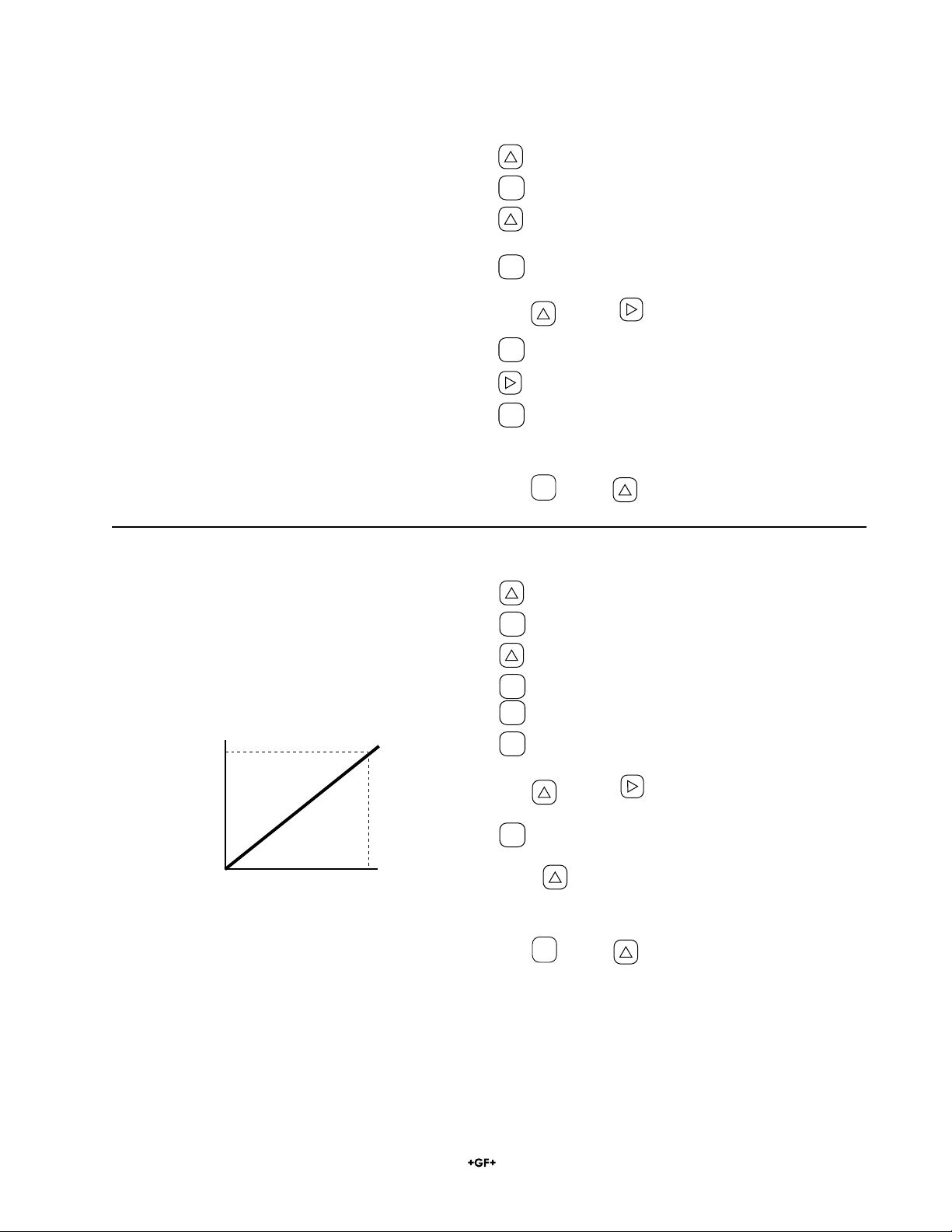
Set the 4-20 mA Range (FLOW SPAN-1)
• The analog output (4-20 mA) corresponds to the range
setting.
• If “INPUT ERROR” appears, the setting is beyond the
operating range of the instrument.
• After changing the RANGE, adjust zero point.
• If “PIPING PARAMETERS” or “FLOW UNIT” are
changed, FLOW SPAN must be reset.
Flow rate
SPAN-1
4mA
20mA
100%0

18
Scaled for footer
Signet 3350/3550 Ultrasonic Flowmeter
Set Dual 4-20 mA Ranges (FLOW SPAN-2)
• Use FLOW SPAN-2 to set the 4-20 mA output to
automatically switch scales as the flow rate varies.
• If it is not used, set the range of FLOW SPAN-2 to 0.
• The HYSTERESIS can be set from 0 and 10% of the
smaller range.
• When the source of DO1 or DO2 is set to “FLOW
SPAN-2”, a contact outputs “SPAN-2” action. Select
[ACTIVE ON] or ACTIVE OFF separately.
• Always reset the ZERO ADJUST after changing the
range value.
• The dual ranges can be set to measure reverse flow.
Use the “-” sign in the first position when setting the
reverse flow range.
Hysteresis
SPAN-1
SPAN-2
4mA
20mA
0
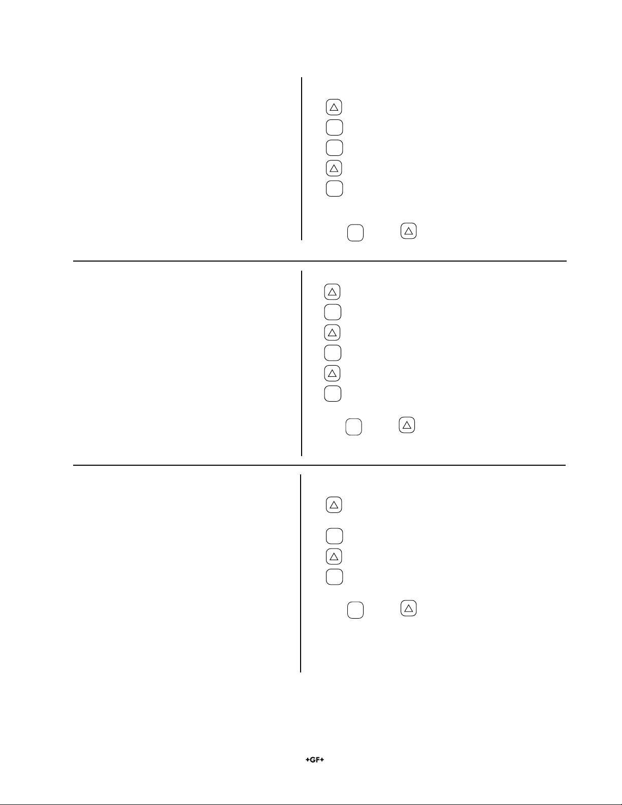
Press: Display shows:
“FLOW SPAN-2”.
ENT
Cursor blinks
Use key and key to set maximum flow rate.
ENT
Stores the new setting into memory
“HYSTERESIS”.
ENT
Cursor blinks
Use key and key to set hysteresis.
ENT
Stores the new setting into memory
“BURNOUT”
ENT
Current selection blinks
Scroll to new setting.
ENT
Stores the new setting into memory
“BURNOUT TIMER” and “10 s”
ENT
Cursor blinks
Use key and key to set new time delay.
ENT
Stores the new setting into memory.
Use
ESC
key and key to resume measurement mode.
Set BURNOUT mode for the 4-20 mA output
BURNOUT is the error mode for the 4-20 mA output.
Specify how the 4-20 mA output will react during loss of signal, etc. due to hardware error, empty pipe or ingress of
bubbles.
The options are:
HOLD (factory set): Retain the last good value
OVER SCALE: Outputs 23.2 mA.
UNDER SCALE: Outputs 0.8 mA.
ZERO: Outputs 4 mA.
BURNOUT TIMER 0 to 100 seconds
(factory set at 10 sec).
(time delay from error detection to response)
19
Scaled for footer
Signet 3350/3550 Ultrasonic Flowmeter
Press: Display shows:
2x OUTPUT SETUP
ENT
ZERO ADJUST
4x “RANGE” and “FLOW RATE”
ENT
“FLOW RATE” blinks
“TOTAL” blinks
ENT
“TOTAL MODE” and “START”
“PULSE VALUE” and 1mL”
(or current selection)
ENT
Cursor blinks
Use key and key to set the volume represented
by each pulse.
ENT
Stores the PULSE VALUE into memory
PULSE WIDTH and 5.0 ms (or current
selection)
ENT
Cursor blinks on 2nd line.
Press to scroll to select pulse width value
ENT
Stores the new value into memory
Set Pulse Output and Totalizer functions
Set the pulse value, pulse width and preset value.
Then, reset the total value to a preset value (factory set at 0), and start a total.
BURNOUT(TOTAL)
Determines the behaviour of the totalizer when an error occurs due to an empty pipe interior or bubbles mixed in fluid
(common to total indication and total pulse output).
HOLD: Stops the total (as factory set).
COUNT: Continues the total according to a flow rate marked immediately before the error occurrence.BURNOUT TIMER
Sets the time from error occurrence to error processing.l Settable range: 0 to 100 sec (factory set at 10 sec).The
total continues until the burnout timer is actuated.
Press: Display shows:
TOTAL PRESET and 0 mL
ENT
Cursor blinks.
Use key and key to set the value where the
totalizer will start after a reset
ENT
Stores the new value into memory
BURNOUT (TOTAL) and HOLD
ENT
HOLD blinks.
Scroll to select BURNOUT action.
ENT
Stores the new setting into memory
“BURNOUT TIMER” and “10 s”
ENT
Cursor blinks
Use key and key to set new time delay.
ENT
Stores the new setting into memory.
Use
ESC
key and key to resume measurement mode.

20
Scaled for footer
Signet 3350/3550 Ultrasonic Flowmeter
Start, Stop and Reset the Totalizer
• The total is started, stopped or reset manually, from this menu.
START: Total output starts
STOP: Total output stops
RESET: Reset the total memory to the preset value.
This setting simultaneously resets both forward total memory and reverse total memory.
After performing a RESET the total function will remain STOPPED until “START” is executed.
Press: Display shows:
2x OUTPUT SETUP
ENT
ZERO ADJUST
4x “RANGE” and “FLOW RATE”
ENT
“FLOW RATE” blinks
“TOTAL” blinks
ENT
“TOTAL MODE” and “START”
ENT
“START” blinks
Scroll to select RESET or STOP.
ENT
START, STOP or RESET is implemented.
The TOTAL memory will be reset to the PRESET value
After resetting, the total operation automatically stops.
To resume a total, execute “START”:
ENT
“STOP” blinks
Scroll to select START.
ENT
START is implemented.
Use
ESC
key and key to resume measurement mode.
Total Count Reset Reset Reset Reset
Time
Preset Value
This manual suits for next models
1
Table of contents
Other Signet Measuring Instrument manuals


Popular Measuring Instrument manuals by other brands


ABB
ABB Aztec 600 manual

Ripley
Ripley MILLER VIS300 user guide

engelmann
engelmann microCLIMA DE-16-MI004-PTB025 Installation and operating instructions

METREL
METREL MI 3321 MultiservicerXA instruction manual

Precision Medical
Precision Medical 1MFA3001 user manual

Trend Micro
Trend Micro EdgelIPS Pro-2096 Quick setup guide

Endress+Hauser
Endress+Hauser Levelflex FMP50 operating instructions

Elenco Electronics
Elenco Electronics XK-700K Assembly and instruction manual

Vernier
Vernier Go Wireless GW-EHR manual

Grandway
Grandway FHP3P01 user guide

Master Meter
Master Meter Register Install & Remove

Flux
Flux FLUXTRONIC FMJ 100 Original attachment