Signet 2551 User manual

1
2
3
4
JP2
FREQUENCY OUT
SERIAL (S L) OUT
3
Connect output signals and power
to this 4-terminal block.
1.
Sensor Type Pipe Size Jumper Position
2551-P0/T0/V0 ½ in. to 2½ in.
DN15 to DN65
2551-P0/T0/V0 3 in. to 4 in.
DN80 to DN100
2551-P1/T1/V1 5 in. to 6 in.
DN125 to DN150
2551-P1/T1/V1 8 in.
DN200
2551-P2/T2/V2 10 in. to 12 in.
DN250 to DN300
2.
3.
4.
5.
4.
Signet 2551 Blind Magmeter
*3-2551.090*
3-2551.090 Rev L 10/12 English
1. Quick Start Guide
This manual contains the general installation, wiring and calibration data for the Signet 2551-XX-11 Magmeter with Frequency or
Digital (S3L) data output, and for the Signet 2551-XX-12 Magmeter with 4 to 20 mA output. The basic steps are outlined on this page.
See each referenced section for detailed information.
1. Congure the Hardware
2551-XX-11 ONLY: Position this Jumper to select
Digital (S3L) output or Frequency output. Sec. 5 Pg. 4.
2. Position the PIPE SIZE jumper according to your
pipe size. Sec. 5 Pg. 4.
3. Install the Magmeter into the pipe.
Use Signet installation ttings ONLY.
The installation tting is critical to Magmeter
performance. Sec. 3 Pg. 3.
4. Connect POWER and OUTPUT wiring.
Frequency out: Sec. 8.1 Pg. 6.
Digital (S3L) out: Sec. 8.2 Pg. 6.
4 to 20 mA out: Sec. 7 Pg. 5.
GROUNDING
Without a good earth ground, the Magmeter may not
operate efciently. Sec. 6 Pg. 5.
5. Route the wiring out through the two cable ports.
Use appropriate hardware to secure the 2551 from
moisture intrusion. One Liquid Tight Connector is
included. Sec. 5 Pg. 4.
Topic: Page
1. Quick Start Guide 1
2. Specications 2
3. Installation: Pipe Fittings 3
4. Selecting a Location 3
5. Hardware Conguration 4
6. General Installation and Grounding Tips 5
7. Wiring the Magmeter with 4 to 20 mA Loop 5
Topic: Page
8. Wiring the Magmeter
with Frequency or Digital (S3L) Output 6
9. Calibration and Software Conguration 6
10. Calibration Data 7
11. Maintenance and Troubleshooting 11
12. Ordering Information 12
English
Description
The Signet 2551 Magmeter is an insertion-style magnetic ow sensor. The patented sensor design is available in a variety of corrosion-
resistant materials to provide long-term reliability and minimal maintenance costs. Wetted material combinations include PP/316 SS,
PVDF/Hastelloy-C and PVDF/Titanium. The 2551 installs quickly and securely into a wide selection of ow ttings to deliver accurate
ow measurement in pipe sizes ranging from DN15 to DN900 (½ in. to 36 in.).
Signet 2551 Magmeters are available with a frequency output or Digital (S3L) output for use with the Signet 5600 Batch Controller, 8900
Multi-Parameter Controller or 9900 Transmitter, or with a 4 to 20 mA output for a direct input to a PLC, SCADA or telemetry system.
All 2551 Magmeters feature empty pipe detection and LED-assisted diagnostics. The Signet 3-0250 USB to Digital (S3L) set-up tool is
available to customize every performance feature in the 2551 to adapt it to the specic application requirements.
2 2551 Magmeter
2. Specications
10
20
30
40
50
60
70
80
90
100
110
120
130
140
150
160
170
180
.7
1.4
2.1
2.8
3.4
4.1
4.8
5.5
6.2
6.9
7.6
8.3
9.0
9.7
10.3
11.0
11.7
12.4
(bar)(psi)
0
-20 020
40 60 80 100 120
°F
°C
-4 32 68 104 140 176 212 248
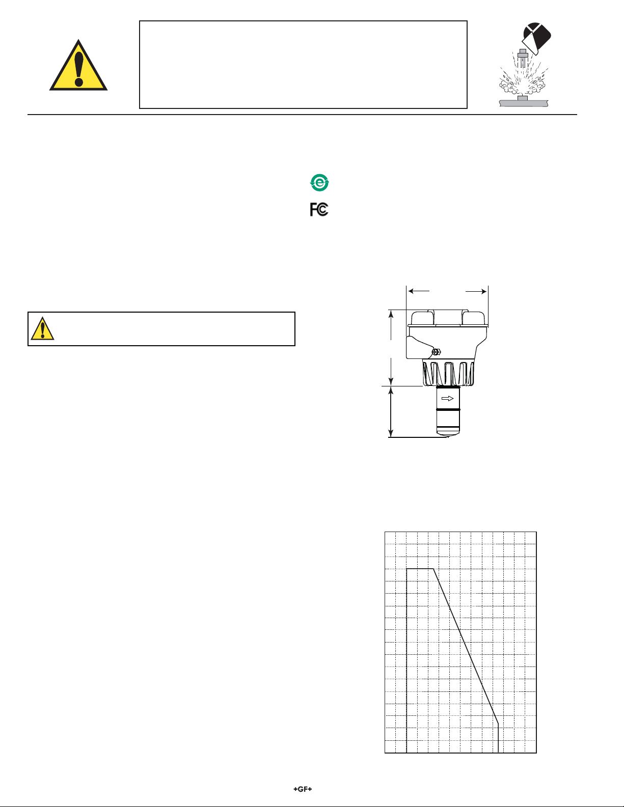
Dimensions
Operating Temperature/Pressure
General
Pipe size range: DN15 to DN 900 (0.5 in. to 36 in.)
Flow Range
• Minimum: 0.05 m/s (0.15 ft/s)
• Maximum: 10 m/s (33 ft/s)
Linearity: ± 1% reading plus 0.01m/s (0.033 ft/s)
Repeatability: ± 0.5% of reading @ 25 °C (77 °F)
Min. Conductivity: 20 S/cm
Wetted Materials:
• Sensor body and Electrodes and Grounding ring:
• -P0, -P1, -P2: Polypropylene and 316L SS
• -T0, -T1, -T2: PVDF and Titanium
• -V0, -V1,-V2: PVDF and Hastelloy-C
• O-rings: FPM (standard); EPDM, FFPM (optional)
The user is responsible for determining the chemical
suitability of these materials for a specic application.
Electrical
Power Requirements
• 4 to 20 mA: 21.6 to 26.4 VDC, 22.1 mA max.
• Frequency: 5 to 26.4 VDC, 15 mA max.
• Digital (S3L): 5 to 6.5 VDC, 15 mA max.
Reverse polarity and short circuit protected
Current output (4 to 20 mA):
• Loop Accuracy: 32 A max. error (25 °C @ 24 VDC)
• Isolation: Low voltage < 48 VAC/DC from electrodes
and auxilary power
• Max cable: 300 m (1000 ft.)
• Error condition: 22.1 mA
• Max. Loop
Resistance: 300
• Compatible with PLC, PC or similar equipment
Frequency output:
• Max. Pull-up
Voltage: 30 VDC
• Compatible with Signet 5600, 8900, 9900
Digital (S3L) Output:
• Serial ASCII, TTL level 9600 bps
• Compatible with Signet 8900, 9900
Environmental Requirements
• Case: PBT
• Display: Polyamide
Storage Temperature: -20 to 70 °C (-4 to 158 °F)
Relative Humidity: 0 to 95% (non-condensing)
Operating Temperature:
• Ambient: -10 to 70 °C (14 to 158 °F)
• Media: 0 to 85 °C (32 to 185 °F)
Max. operating pressure:
• 10.3 bar @ 25 °C (150 psi @ 77 °F)
• 1.4 bar @ 85 °C (20 psi @ 185 °F)
Standards and Approvals
CE, UL
NEMA 4X / IP65 Enclosure (with cap installed)
94 mm
(3.7 in.)
79.25 mm
(3.12 in.)
-X0
-X1
-X2
Pipe Range:
1/2 to 4 in. -X0 = 58 mm (2.3 in.)
5 to 8 in. -X1 = 91 mm (3.6 in.)
10 to 36 in. -X2 = 167 mm (6.6 in.)
X = Sensor Bod
y
P
,
T
,
or V
China RoHS
For more information go to www.gfsignet.com
SAFETY INSTRUCTIONS
1. Depressurize and vent system prior to installation or removal.
2. Conrm chemical compatibility before use.
3. Do not exceed maximum temperature/pressure specications.
4. Wear safety goggles or face shield during installation/service.
5. Do not alter product construction.
6. Disconnect power before attempting any service or wiring.
Declaration of Conformity according to FCC Part 15
This device complies with Part 15 of the FCC rules.
Operation is subject to the following two conditions:
(1) This device may not cause harmful interference, and,
(2) This device must accept any interference received,
including interference that may cause undesired operation.
32551 Magmeter
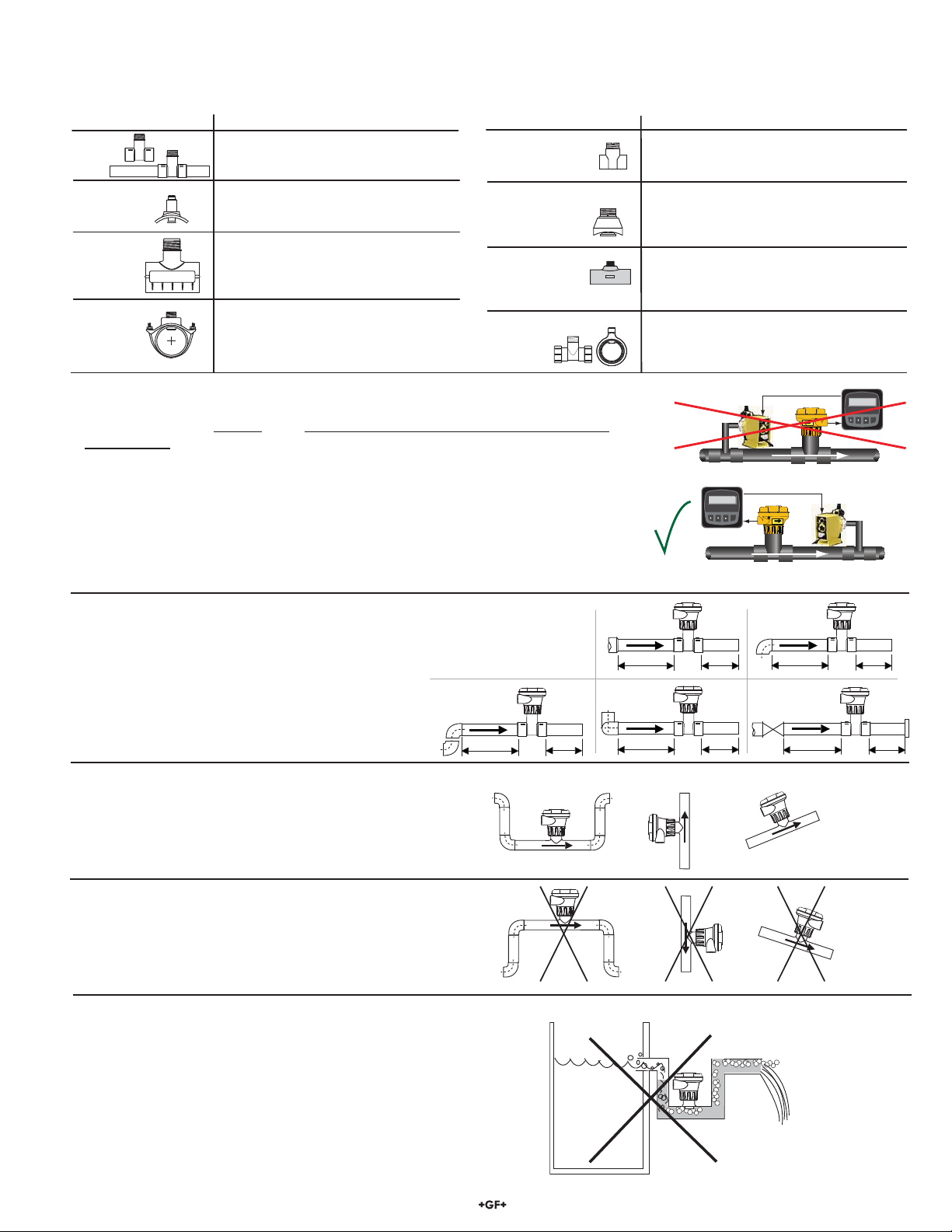
4. Selecting a Location
• The 2551 requires a full pipe and a fully developed turbulent ow prole for accurate
measurement.
• If the piping system harbors air pockets or bubbles, take steps to locate the sensor so the
air pockets will not contact the electrodes.
• In vertical installations, assemble the 2551 so the conduit ports are facing downward.
This prevents condensation inside the conduit from being directed into the 2551
electronics housing.
• Chemical injection systems can temporarily alter the uid conductivity and cause
anomalies in the magmeter measurement.
To avoid this problem, install the magmeter UPSTREAM of the injection point.
Reducer
15 x I.D. 5 x I.D. 20 x I.D. 5 x I.D.
90° Elbow
40 x I.D. 5 x I.D.
2 x 90° Elbow
3 dimensions
25 x I.D. 5 x I.D.
2 x 90° Elbow
50 x I.D. 5 x I.D.
Pump/Valve
+GF+
+GF+
+GF+
+GF+
+GF+
OKOK OK
Vertical flow is OK if the pipe remains full at all times.
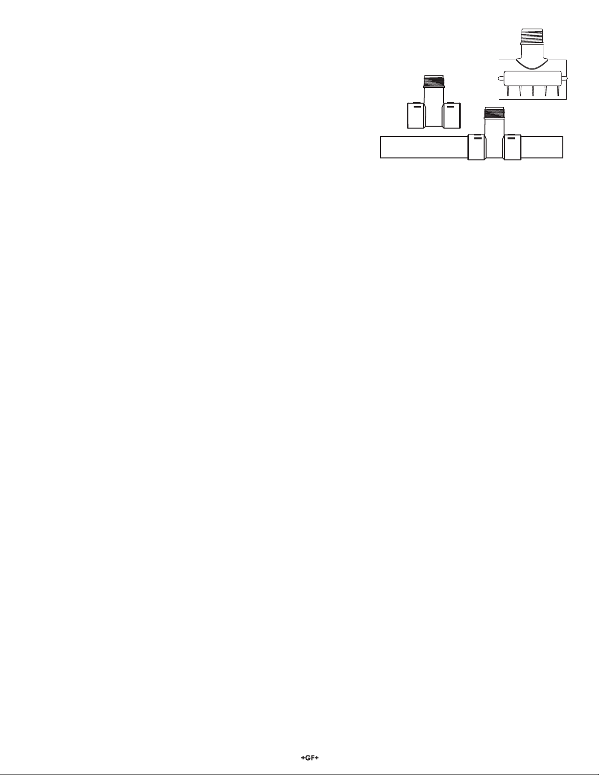
3. Installation: Pipe ttings
Georg Fischer offers a wide selection of installation ttings that control the position of the Magmeter electrodes in relation to the
dimensions of the pipe. You will nd a complete list of order numbers for installation ttings in the Calibration Tables on pages 7-10.
Select a location with sufcient distance of
straight pipe immediately upstream of the sensor.
Locating the sensor in a trap or where the ow is
upward helps to protect the sensor from exposure
to air bubbles when the system is in operation.
These congurations are not recommended
because it is difcult to keep the pipe full.
Type Description
• 2 to 4 inch, cut 1-7/16 inch hole in pipe
• Over 4 inch, cut 2-1/8 inch hole in pipe
• Special order 14 in. to 36 in.
• 0.5 to 2 inch versions
• MPVC or CPVC
• 2 to 4 inch, cut 1-7/16 inch hole in pipe
• 6 to 8 inch, cut 2-1/8 inch hole in pipe
• Available in 10 and 12 inch sizes only
• Cut 2-1/2 inch hole in pipe
• Weld in place using solvent cement
Iron, Carbon Steel,
316 SS
Threaded tees
Carbon steel &
stainless steel
Weld-on
Weldolets
• 2 to 4 inch, cut 1-7/16 inch hole in pipe
• Over 4 inch, cut 2-1/8 inch hole in pipe
• For pipes from DN 15 to 50 mm
• PP or PVDF
Type Description
Plastic
tees
Union Fittings and
Wafers
PVC
Clamp-on
Saddles
Iron
Strap-on
saddles
PVC
Glue-on
Saddles
• 1.5 in. to 2 in. PVDF insert
Fiberglass
tees
FPT
• 0.5 to 2 in. versions
• Mounts on threaded pipe ends
In a gravity-ow system, the tank must be designed
so the level does not drop below the outlet.
This causes the pipe to draw air in from the tank.
If air bubbles pass across the Magmeter
electrodes, the output will become erratic.
Flow
Flow
Flow6.25 GPM
Total1234567.8>
ENTER
Signet Flow
Transmitter
Flow6.25 GPM
Total1234567.8>
ENTER
Signet Flow
Transmitter
4 2551 Magmeter
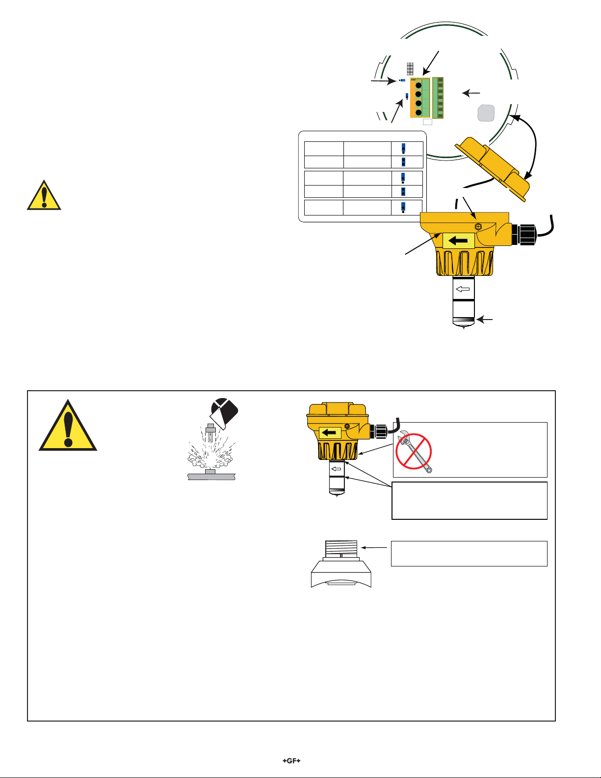
Important:
• The directional arrow on the sensor body MUST be pointed DOWNSTREAM for correct operation.
(Digital (S3L) and 4 to 20 mA will not work if ow is against direction of arrow).
• The FLOW arrow decal can be placed directly on the pipe to identify the direction of ow.
• Use a cable gland or a liquid tight connector to seal the cable ports from water intrusion.
• The yellow housing may be reversed to align the conduit ports as required.
• If the Magmeter is installed on a vertical pipe, the conduit ports should be turned to point downward.
This will prevent condensation from being channeled into the enclosure.
• Use plumber's tape or a suitable sealant on cable ports.
5. Hardware Conguration
Whether using the 2551-XX-11 (with frequency or Digital (S3L)
output) or the 2551-XX-12 (with 4 to 20 mA output), the wiring
terminals located on the inside of the yellow cover are identical.
All of the connections from the Magmeter to external equipment
(PLC, Datalogger, Chart Recorder, Flow meter, etc.) are made at
the large 4-position terminal connector.
When the cover is removed the wiring from the sensor can be
seen connected to the smaller terminal block. These connections
should always remain connected to prevent inadvertent damage
or miswiring.
The terminals on the 2551 Magmeter are designed for conductors
from 16 AWG to 22 AWG.
WARNING!
If the second conduit port is used, carefully drill the
opening. (The plastic is too strong to be punched out.)
• Secure the Magmeter in a vise to prevent damage or injury.
• The plastic inside the port is very thin. Do not allow the drill to
penetrate too deeply and damage the Magmeter wiring.
1
2
3
4
JP2
White
Yellow
Red
Black
Brown
Blue
Not used
The factory connects
the sensor cable to the termi
n
inside the yellow cover.
This blue jumper selects
frequency output or
S3L serial data output
in the 3-2551-XX-11
(Not used on 2551-XX-12 models)
The user must connect output cables to
this 4-terminal block.
JP2 is for factory use only.
MAKE NO CONNECTIONS.
Use the yellow decal to mark
the direction of flow on the pipe
Set this blue jumper according to the pipe size.
External Earth Ground Terminal
Sensor Type Pipe Size Jumper Position
2551-P0/T0/V0 ½ in. to 2½ in.
DN15 to DN65
2551-P0/T0/V0 3 in. to 4 in.
DN80 to DN100
2551-P1/T1/V1 5 in. to 6 in.
DN125 to DN150
2551-P1/T1/V1 8 in.
DN200
2551-P2/T2/V2 10 in. to 12 in.
DN250 to DN300
Sensor grounding ring
3-9000.392-1
Liquid tight connec
(one supplied)
Flow
FAILURE TO FOLLOW THESE INSTRUCTIONS MAY RESULT IN
THE SENSOR BEING EJECTED FROM THE PIPE!
• DO NOT USE ANY TOOLS ON THE RETAINING CAP.
HAND TIGHTEN ONLY.
• LUBRICATE O-RINGS WITH A NON-PETROLEUM BASED,
VISCOUS LUBR ICANT (GREASE) COMPATIBLE WITH
THE SYSTEM.
• DO NOT USE THREAD SEALANT OR LUBRICANTS ON THE
RETAINING CAP OR ON THE PLASTIC FITTING THREADS.
• IF LEAKING IS OBSERVED FROM THE RETAINING CAP, IT INDICATES DEFECTIVE OR WORN O-RINGS ON THE SENSOR.
DO NOT ATTEMPT TO CORRECT BY FURTHER TIGHTENING.
WARNING!
DO NOT USE thread sealant or
lubricants on the fitting threads.
Do not use any tools to
tighten the yellow retaining
cap. DO NOT USE thread
sealant or lubricants on
retaining cap!
Lubricate O-rings with a viscous
non-petroleum based lubricant
(grease) compatible with the system.
Flow
CHEMICAL COMPATIBILITY WARNING
The retaining nuts of Magmeters are not designed for prolonged contact with aggressive substances. Strong acids, caustic substances
and solvents or their vapor may lead to failure of the retaining nut, ejection of the sensor and loss of the process uid with possibly
serious consequences, such as damage to equipment and serious personal injury. Retaining nuts that may have been in contact with
such substances, e.g. due to leakage or spilling, must be replaced.

52551 Magmeter
6. General Installation and Grounding Tips
Sensor conditioning
The Magmeter output signal may be unstable immediately after installation. Allowing the sensor to soak in a full pipe (or in any
container of water) for 24 hours will stabilize the performance.
• Very low conductivity uids may require a longer conditioning period. (The Magmeter will not operate properly in uids where the
conductivity is less than 20 S/cm.)
Grounding
The 2551 Magmeter is unaffected by moderate levels of electrical noise. However, in some applications it may be necessary to ground
portions of the system to eliminate electrical interference. The grounding requirements will vary with each installation.
7. Wiring the 2551-XX-12 Magmeter with 4 to 20 mA Loop Output
The 2551-XX-12 Magmeter is a traditional 2-wire passive 4 to 20 mA loop transmitter.
• External loop power (24 VDC ± 10%) is required. See Ordering Information for power supplies.
• The maximum loop resistance the Magmeter can accomodate is 300 .
• All 2551-XX-12 Magmeters are shipped from the factory with the 4 to 20 mA
output scaled for 0 to 5 m/s (0 to 16.4 ft/s). If this operating range is suitable,
no adjustments are necessary.
• The Calibration Tables on pages 7-10 list the 20 mA setpoint for each
installation tting. Use this information to program the 4 to 20 mA range of
the loop device (PLC, Datalogger, recorder, etc.)
• The 3-0250 USB to Digital (S3L) Conguration/Diagnostic Tool is required to
change the operating range. Loop + (24 VDC)
Loop - (Ground)
4-20 mA Loop
monitor
(Maximum 300 Ω)
+
+
-
-
24 VDC ± 10%
1
2
3
4
2551 Magmeter
Grounding rings on plastic pipe
(Install between flanges)
or
metal stra
p
s on metal
p
i
p
e
Earth ground
Sensor
Grounding ring
(10 cm to 1.3 m) (10 cm to 1.3 m)
4 in. to 50 in. 4 in. to 50 in.
Instrument
4.
1.
2.2.
Do not terminate
shield at Magmeter
3.
dInstall uid grounding devices immediately upstream and
downstream of the Magmeter.
Connect the uid grounds to the Earth ground terminal on the 2551.
Use anged grounding rings or metal electrodes on plastic pipes, or
metal clamps on metal pipes.
Fluid grounds must be in direct contact with the uid, and as near to
the Magmeter as possible.
eThe shield from the output cable must be terminated at the remote
instrument ONLY.
This shield must be connected at only one end!
fConnect an additional wire (minimum AWG 14/2.08 mm2) from the
remote instrument ground to the Magmeter ground terminal.
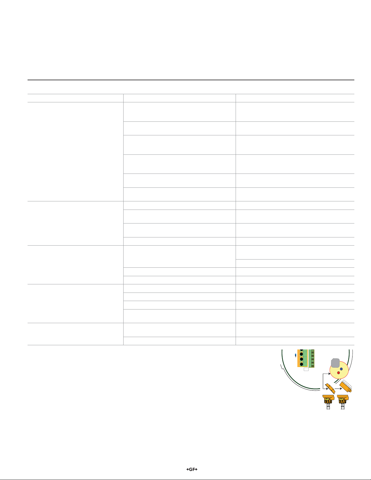
One or more of the following steps may be
applied if the 2551 Magmeter is affected by
electrical noise:
cThe ground terminal on the outside of the
yellow housing is connected internally
to the grounding ring at the tip of the
sensor. Connect a wire (14 AWG/2.08 mm2
recommended) from this terminal directly to a
local Earth ground.
6 2551 Magmeter
• When the blue jumper illustrated here is placed over both pins, the
2551-XX-11 outputs an open collector frequency signal that can be
connected to any powered Signet ow meter (models 5600, 8900,
9900).
• 5 VDC power is provided to the 2551 Magmeter by all Signet ow
instruments. No additional power is required.
• The frequency output will be displayed as positive ow
regardless of the ow direction.
• When the blue jumper illustrated here is removed (or placed over
one pin for storage) the 2551-XX-11 outputs a Digital (S3L) signal
compatible with the Signet 8900 and 9900.
• The 2551 receives 5 VDC power from the 8900 or 9900. No
additional power is required.
• The 8900 will display 0 (Zero) ow rate during periods of
reverse ow. The 9900 will display negative numbers to
indicate reverse ow.
• The maximum cable length from the 2551 to the 8900 or 9900
depends on the 8900 or 9900 conguration. Refer to the 8900 or
9900 manual for complete information.
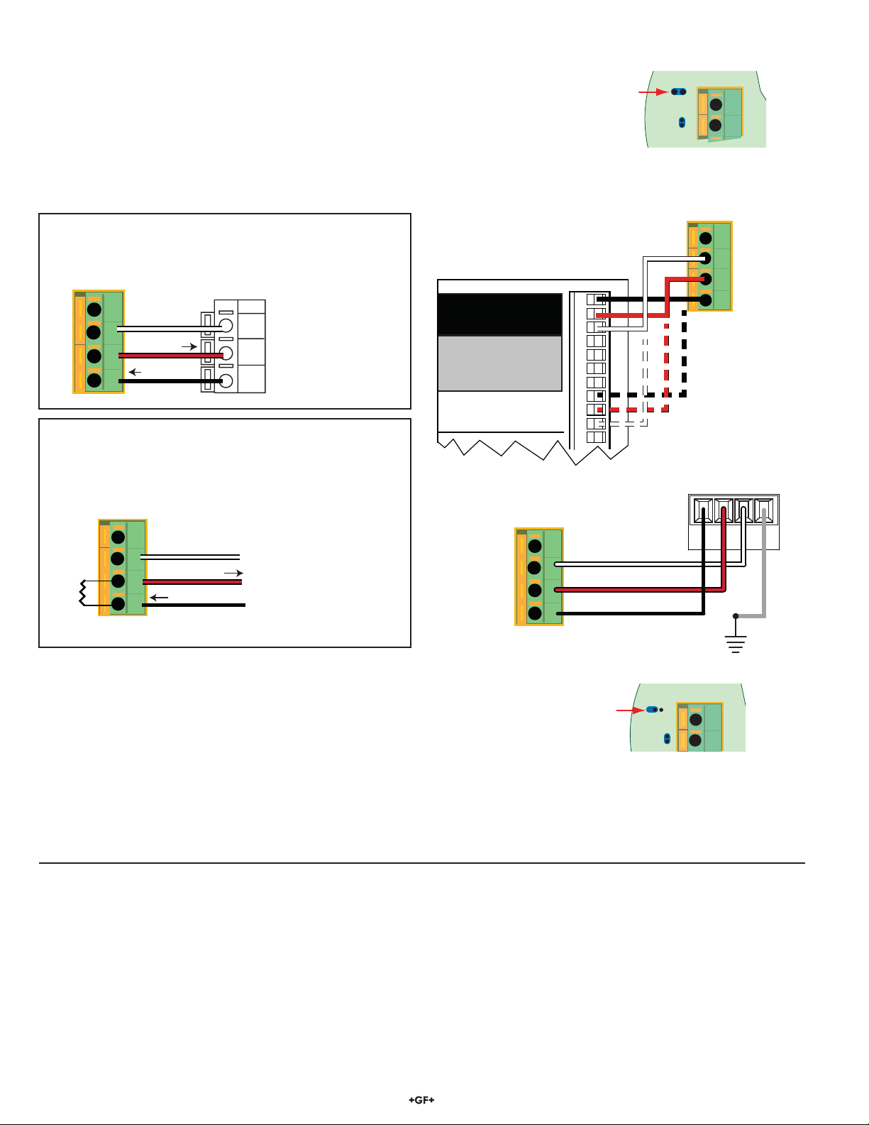
Blue Jumper OFF = S3L OUT
S L
3
3
4
8. Wiring the 3-2551-11 with Frequency or Digital (S3L) output
1
2
3
4
10K
5-24 VDC
Ground
Not used
Frequency Out
2551 Magmeter
Install a pull-up resistor when connecting the
2551 Magmeter to other manufacturer's flowmeters.
2551 Frequency Out to other manufacturer's equipment
Blue Jumper ON = FREQ OUT
3
4
Frequency
1
2
3
4
5-24 VDC
Ground
Not used
Sensr Gnd
(SHIELD)
Sensr IN
(RED)
Sensr V+
(BLACK)
2551 Magmeter
Flow Transmitter
Frequency
AUX power MUST be connected on the 5600 Flow Transmitter
to provide power to the 2551.
3-8900.621C
I/O Module 3-8900.401-X
1
2
3
4
5
6
7
8
9
10
11
+5VDC (Black)
Freq. Input (Red)
GND (Shield)
+5VDC (Black)
Freq. Input 2 (Red)
S L (Red)
GND (White/Shield)
+5VDC (Black)
S L (Red)
GND (White/Shield)
3
3
Frequency
Input
1
Frequency
Input 2
OR
S3L
Input
2
S3L
Input
1
1
2
3
4
Freq.
S3L
Ground
+5 VDC
Not used
Data
2551 Magmeter
2551 Wiring to Signet 8900 and 9900
2551 Frequency Out to Signet 5600
9. Calibration and Software Conguration
No calibration is necessary to begin using the 2551. The application and performance settings are pre-set to meet the requirements of
most applications.
The 2551 application and performance settings can be customized using the Signet 3-0250 USB to Digital (S3L) Conguration/
Diagnostic Tool and software. Refer to the Signet 3-0250 USB-to-S3L Conguration/Diagnostic Tool manual for details to adjust the
following parameters:
• 4 to 20 mA span: Factory setting is 0 to 5 m/s. Can be customized to any range.
• Noise Rejection Filter: Factory set for 60 Hz. Can be changed to 50 Hz.
• Low Flow Cutoff: Factory setting is 0.05 m/s. Can be customized to any velocity.
• Averaging Time: Factory setting is 14 seconds. Can be customized from 0.1 seconds to 100 seconds.
• Sensitivity: Factory setting is 25% of full scale. Can be customized to any % of full scale.
If connecting the 2551 Magmeter to a ow instrument from
another manufacturer, 5 to 24 VDC power must be provided to
the 2551. A 10 K pull-up resistor (not supplied) must also be
connected between terminals 1 and 2.
8.1 Wiring: Frequency output (Compatible with all POWERED Signet Flow instruments.)
8.2 Wiring: S3L output (Compatible with 8900 Multi-Parameter Controller and 9900 Transmitter only)
DATA
GND
SHLD
V+
1
2
3
4
2551 Magmeter
9900 Transmitter
+5 VDC
Ground
Not used
Frequency or S3L
72551 Magmeter
10. Calibration Data: K-factors and Full Scale Current Values
Plastic Installation Fittings: PVC Tees and Saddles
Pipe Size
(In.)
Fitting
Type
K-Factor
Gallons
K-Factor
Liters
20 mA=
in GPM
20 mA=
in LPM
SCH 80 PVC-U TEES FOR SCH 80 PVC PIPE
½ MPV8T005 2277.0 601.58 13.1 49.6
¾ MPV8T007 1407.6 371.90 20.97 79.38
1 MPV8T010 861.17 227.52 34.21 129.5
1¼ MPV8T012 464.91 122.83 67.1 253.99
1½ MPV8T015 331.43 87.56 92.54 350.25
2 MPV8T020 192.89 50.96 145.15 549.38
SCH 80 PVC TEES FOR SCH 80 PVC PIPE
2½ PV8T025 131.46 34.73 228.2 863.74
3 PV8T030 82.52 21.80 363.55 1376.04
4 PV8T040 44.78 11.83 669.88 2535.49
SCH 80 PVC TEES FOR SCH 80 CPVC PIPE
½ MCPV8T005 2277.0 601.58 13.18 49.87
¾ MCPV8T007 1407.6 371.90 21.31 80.67
1 MCPV8T010 861.17 227.52 34.84 131.86
1¼ MCPV8T012 464.91 122.83 64.53 244.24
1½ MCPV8T015 331.43 87.56 90.52 342.62
2 MCPV8T020 192.89 50.96 155.53 588.70
SCH 80 PVC SADDLES FOR SCH 80 PVC PIPE
2 PV8S020 193.83 51.21 154.77 585.81
2½ PV8S025 138.01 36.46 217.38 822.78
3 PV8S030 83.89 22.16 357.62 1353.60
4 PV8S040 40.88 10.80 733.88 2777.74
6 PV8S060 22.53 5.95 1331.85 5041.06
8 PV8S080 12.52 3.31 2395.41 9066.64
10 PV8S100 7.94 2.10 3778.75 14302.57
12 PV8S120 5.71 1.51 5256.69 19896.57
SCH 80 PVC SADDLES FOR SCH 40 PVC PIPE
2 PV8S020 180.01 47.56 166.66 630.81
2½ PV8S025 123.72 32.69 242.49 917.82
3 PV8S030 75.81 20.03 395.71 1497.76
4 PV8S040 41.87 11.06 716.56 2712.19
6 PV8S060 19.71 5.21 1521.92 5760.46
8 PV8S080 11.73 3.10 2558.12 9682.50
10 PV8S100 7.43 1.96 4037.60 15282.3
12 PV8S120 5.23 1.38 5734.87 21706.48

8 2551 Magmeter
Pipe Size
(Metric)
Fitting
Type
K-Factor
Gallons
K-Factor
Liters
20 mA=
in GPM
20 mA=
in LPM
POLYPROPYLENE FITTINGS (DIN/ISO, BS, ANSI)
DN15 PPMT005 2192.73 579.32 13.68 51.78
DN20 PPMT007 1327.81 350.81 22.59 85.52
DN25 PPMT010 737.16 194.76 40.70 154.04
DN32 PPMT012 453.46 119.81 66.16 250.41
DN40 PPMT015 275.03 72.66 109.08 412.86
DN50 PPMT020 164.17 43.35 182.74 691.66
PVDF FITTINGS (DIN/ISO, BS, ANSI)
DN15 SFMT005 1946.49 514.26 15.41 58.34
DN20 SFMT007 1158.05 305.96 25.91 98.05
DN25 SFMT010 749.09 197.91 40.05 151.58
DN32 SFMT012 439.51 116.12 68.26 258.36
DN40 SFMT015 248.93 65.77 120.52 456.16
DN50 SFMT020 146.85 38.80 204.30 773.26
PVC FITTINGS (DIN/ISO, BS, ANSI)
DN15 PVMT005 2067.76 546.30 14.51 54.91
DN20 PVMT007 1136.61 300.29 26.39 99.90
DN25 PVMT010 716.52 189.31 41.87 158.47
DN32 PVMT012 446.07 117.85 67.25 254.56
DN40 PVMT015 278.83 73.67 107.59 407.23
DN50 PVMT020 159.36 42.10 188.26 712.55
Plastic Installation Fittings for Metric Pipes:
Polypropylene True Union Tees and Wafers
PVDF True Union Tees
PVC True Union Tees
10. Calibration Data: K-factors and Full Scale Current Values

92551 Magmeter
Pipe Size
(In.)
Fitting
Type
K-Factor
Gallons
K-Factor
Liters
20 mA=
in GPM
20 mA=
in LPM
CARBON STEEL TEES ON SCH 40 PIPE
½ CS4T005 1572.66 415.50 19.08 72.20
¾ CS4T007 1086.73 287.11 27.61 104.49
1 CS4T010 582.34 153.86 51.52 194.99
1¼ CS4T012 377.48 99.73 79.48 300.81
1½ CS4T015 267.79 70.75 112.03 424.02
2 CS4T020 167.85 44.35 178.73 676.48
STAINLESS STEEL TEES ON SCH 40 PIPE
½ CR4T005 1601.26 423.05 18.74 70.91
¾ CR4T007 937.78 247.76 31.99 121.08
1 CR4T010 606.18 160.15 49.49 187.32
1¼ CR4T012 279.68 73.89 107.26 405.99
1½ CR4T015 147.65 39.01 203.19 769.06
2 CR4T020 111.90 29.56 268.09 1014.73
STAINLESS STEEL WELDOLETS ON SCH 40 PIPE
2½ CR4W025 106.31 28.09 282.19 1068.10
3 CR4W030 72.27 19.09 415.12 1571.25
4 CR4W040 36.84 9.73 814.34 3082.28
5 CR4W050 29.28 7.73 1024.70 3878.50
6 CR4W060 20.29 5.36 1478.26 5595.21
8 CR4W080 11.73 3.10 2557.72 9680.96
10 CR4W100 7.45 1.97 4028.83 15249.13
12 CR4W120 5.24 1.39 5722.73 21660.53
CARBON STEEL WELDOLETS ON SCH 40 PIPE
2½ CS4W025 105.70 27.93 283.82 1074.27
3 CS4W030 70.68 18.67 424.45 1606.56
4 CS4W040 36.38 9.61 824.65 3121.30
5 CS4W050 29.28 7.73 1024.70 3878.50
6 CS4W060 20.29 5.36 1478.26 5595.21
8 CS4W080 11.73 3.10 2557.72 9680.96
10 CS4W100 7.45 1.97 4028.83 15249.13
12 CS4W120 5.24 1.39 5722.73 21660.53
GALVANIZED IRON TEES ON SCH 40 PIPE
1 IR4T010 558.50 147.56 53.71 203.31
1¼ IR4T012 334.45 88.36 89.70 339.51
1½ IR4T015 248.97 65.78 120.49 456.07
2 IR4T020 146.00 38.57 205.48 777.76
Metal Installation Fittings:
Carbon Steel Tees and Weld-o-Lets
Stainless Steel Tees and Weld-o-Lets
Galvanized Iron Tees
10. Calibration Data: K-factors and Full Scale Current Values

10 2551 Magmeter
Pipe Size
(In.)
Fitting
Type
K-Factor
Gallons
K-Factor
Liters
20 mA=
in GPM
20 mA=
in LPM
SCH 80 IRON SADDLE ON SCH 80 PIPE
2 IR8S020 194.85 51.48 153.96 582.75
2½ IR8S025 142.28 37.59 210.86 798.10
3 IR8S030 87.53 23.13 342.72 1297.20
4 IR8S040 40.62 10.73 738.58 2795.54
5 IR8S050 29.28 7.74 1024.43 3877.48
6 IR8S060 22.30 5.89 1345.58 5093.03
8 IR8S080 12.52 3.31 2395.41 9066.64
10 IR8S100 7.94 2.10 3778.75 14302.57
12 IR8S120 5.65 1.49 5311.45 20103.83
SCH 80 IRON SADDLE ON SCH 40 PIPE
2 IR8S020 185.35 48.97 161.85 612.61
2½ IR8S025 127.47 33.68 235.36 890.83
3 IR8S030 76.62 20.24 391.54 1481.99
4 IR8S040 40.23 10.63 745.72 2822.57
5 IR8S050 27.32 7.22 1098.24 4156.83
6 IR8S060 19.71 5.21 1521.92 5760.46
8 IR8S080 11.61 3.07 2584.23 9781.30
10 IR8S100 7.36 1.94 4078.8 15438.2
12 IR8S120 5.18 1.37 5793.39 21927.98
Metal Installation Fittings
Iron Saddles
10. Calibration Data: K-Factors and Full Scale Current Values
Pipe Size
(In.)
Fitting
Type
K-Factor
Gallons
K-Factor
Liters
20 mA=
in GPM
20 mA=
in LPM
BRONZE TEES ON SCH 40 PIPE
1 BR4T010 582.34 153.86 51.52 194.99
1¼ BR4T012 330.54 87.33 90.76 343.53
1½ BR4T015 254.76 67.31 117.76 445.71
2 BR4T020 157.36 41.58 190.64 721.58
COPPER TEES FITTING ON COPPER PIPE SCH K
½ CUKT005 2459.19 649.72 12.20 46.17
¾ CUKT007 1108.02 292.74 27.08 102.48
1 CUKT010 649.87 171.70 46.16 174.73
1¼ CUKT012 422.03 111.50 71.09 269.06
1½ CUKT015 281.43 74.35 106.60 403.47
2 CUKT020 136.02 35.94 220.55 834.78
COPPER TEES FITTING ON COPPER PIPE SCH L
½ CUKT005 2406.30 635.75 12.47 47.19
¾ CUKT007 1174.77 310.37 25.54 96.66
1 CUKT010 672.28 177.62 44.62 168.90
1¼ CUKT012 402.84 106.43 74.47 281.87
1½ CUKT015 294.99 77.94 101.70 384.92
2 CUKT020 149.63 39.53 200.50 758.89
COPPER/BRONZE BRAZOLET ON SCH 40 PIPE
2½ BR4B025 117.31 30.99 255.74 967.96
3 BR4B030 78.62 20.77 381.58 1444.28
4 BR4B040 45.13 11.92 664.77 2516.15
5 BR4B050 32.79 8.66 914.91 3462.95
6 BR4B060 22.73 6.01 1319.87 4995.72
8 BR4B080 13.14 3.47 2283.68 8643.71
10 BR4B100 8.34 2.20 3597.17 13615.29
12 BR4B120 5.87 1.55 5109.58 19339.76
Metal Installation Fittings:
Bronze and Copper Tees and Brazolets
112551 Magmeter
11.2 Troubleshooting
11. Maintenance
The 2551 Magmeter requires very little maintenance. There are no user-serviceable components in the Magmeter.
• If the uid contains deposits and solids that may coat the electrodes, a regular cleaning schedule is recommended.
• Do not use abrasive materials on the metal electrodes. Clean with soft cloth and mild detergent only.
• Use a cotton swab and mild detergent to remove deposits on the metal electrodes at the tip of the sensor.
11.1 Environmental Recommendations:
• When used properly, this product presents no inherent danger to the environment.
• Please follow local ordinances when disposing of this or any product with electronic components.
11.3 Troubleshooting with the RED and BLUE LEDs
Both Off: The power is off or the sensor is not connected.
Solid Blue: The power is on, the pipe is full, but there is no ow in the pipe.
Blinking Blue: Normal operation, blink rate is proportional to the ow rate.
Alternating Red-Blue: Empty pipe indication (electrodes are not wet).
Blinking Red: System errors (electrical noise interference).
Solid Red: Instrument error (defective electronics component).
1
2
3
4
D7
D6
Flow Flow
If the 2551 detects an empty pipe:
• Frequency output will be locked to 0 Hz if electrodes are not wet.
• Digital (S3L) output will be locked to 0 if electrodes are not wet.
• 4 to 20 mA will be locked to 4 mA if electrodes are not wet.
• Blue and red LEDs will blink alternately if electrodes are not wet.
If the 2551 detects REVERSE FLOW:
• Frequency out cannot distinguish reverse ow from forward ow. The output will be the absolute value.
• With Digital (S3L) output, reverse ow results in 0 ow rate displayed on 8900 or with negative numbers on the 9900.
• 4-20 mA output can be spanned into negative ow range using the 3-0250 USB Setup Tool and software. (See section 9)
(example: 4-20 mA = –100 to +100 GPM).
Symptom Possible Cause Solution
Output is erratic and unstable.
Magmeter installed too close to upstream
obstruction.
Relocate the magmeter to have straight
uninterrupted pipe upstream of the sensor for
at least 10 x the pipe diameter.
Magmeter located in area exposed to air
bubbles/pockets. Eliminate air bubbles in the pipe.
Magmeter is installed in pipe backwards.
Remove the magmeter and reinstall with the
ow direction arrow on the sensor body pointed
DOWNSTREAM.
Electrical noise is interfering with the
measurement.
Review the grounding of the magmeter and the
pipe. Install adequate Earth ground to allow the
Magmeter to operate properly.
Electrodes are coated with solids. Carefully clean the electrodes. Refer to sensor
manual for details.
New sensor; metal surface not properly
conditioned. Soak sensor overnight in uid.
Output is not 0 when ow is stopped.
Electrodes not adequately conditioned. Soak sensor overnight in uid.
Vibration or other movement in pipe causes
magmeter to detect ow. Increase the Low Flow Cutoff.
Electrical noise interference. Modify grounding to protect the Magmeter from
interference.
Defective Magmeter. Return to factory for service.
4-20 mA current output is incorrect.
Loop device not scaled same as Magmeter.
Use 3-0250 Setup tool to respan the Magmeter
to match Loop device.
Respan Loop device to match Magmeter.
Range Jumper not placed correctly. Set Range Jumper correctly.
Defective Magmeter. Return to factory for service
Frequency output is inoperative
Digital (S3L) output is inoperative.
Loop output is inoperative.
2551 is wrong model. Frequency/S3L model: 3-2551-11
Blue jumper not in correct position. Place blue jumper correctly. (Sec. 5 pg. 4)
Wiring is not correct. Check wiring, make corrections.
Frequency input to other manufacturer's ow
instrument does not have pull-up resistor. Install 10 k resistor. (section 8.1, pg. 6)
Output is 22.1 mA
Conductivity is less than 20 S/cm (the uid
is too clean for Magmeter). Unsuitable application for Magmeter.
Electronic component failure. Return 2551 to factory.

Georg Fischer Signet LLC, 3401 Aero Jet Avenue, El Monte, CA 91731-2882 U.S.A. • Tel. (626) 571-2770 • Fax (626) 573-2057
For Worldwide Sales and Service, visit our website: www.gfsignet.com • Or call (in the U.S.): (800) 854-4090
For the most up-to-date information, please refer to our website at www.gfsignet.com
3-2551.090 Rev. L 10/12 English © Georg Fischer Signet LLC 2012
12. Ordering Information
3-2551-T2-11 159 001 448
3-2551-T2-12 159 001 449
3-2551-V0-11 159 001 257
3-2551-V0-12 159 001 259
3-2551-V1-11 159 001 258
3-2551-V1-12 159 001 260
3-2551-V2-11 159 001 450
3-2551-V2-12 159 001 451
3-2551-P0-11 159 001 105
3-2551-P0-12 159 001 110
3-2551-P1-11 159 001 106
3-2551-P1-12 159 001 111
3-2551-P2-11 159 001 107
3-2551-P2-12 159 001 112
3-2551-T0-11 159 001 108
3-2551-T0-12 159 001 113
3-2551-T1-11 159 001 109
3-2551-T1-12 159 001 114
Sensor Part No.
3-2551
Sensor Body (Transducer) and electrodes/grounding ring materials - Choose one
-P Polypropylene and 316L SS
-T PVDF and Titanium
-V PVDF and Hastelloy C
Pipe size - Choose one
0 DN15 to DN100 (½ to 4 in.)
1 DN125 to DN200 (5 to 8 in.)
2 DN250 to DN900 (10 to 36 in.)
Display Options - Choose One
-1 No Display
Output options - Choose One
1 Frequency, Digital (S3L)
2 4 to 20 mA output
3-2551 -P 0 -1 2 Example Part Number
Replacement Parts and Accessories
Mfr. Part No. Code Description
1220-0021 198 801 186 O-ring, FPM
1224-0021 198 820 006 O-ring, EPDM
1228-0021 198 820 007 O-ring, FFPM
3-2551-11 159 001 215 Magmeter electronics, no display, frequency or Digital (S3L) output
3-2551-12 159 001 216 Magmeter electronics, no display, 4 to 20 mA output
3-2551-P0 159 001 211 PP/316L SS, DN15 to DN100 (½ to 4 in.) pipe
3-2551-P1 159 001 212 PP/316L SS, DN125 to DN200 (5 to 8 in.) pipe
3-2551-P2 159 001 444 PP/316L SS, DN250 to DN900 (10 to 36 in.) pipe
3-2551-T0 159 001 213 PVDF/Titanium, DN15 to DN100 (½ to 4 in.) pipe
3-2551-T1 159 001 214 PVDF/Titanium, DN125 to DN200 (5 to 8 in.) pipe
3-2551-T2 159 000 445 PVDF/Titanium, DN250 to DN900 (10 to 36 in.) pipe
3-2551-V0 159 001 376 PVDF/Hastelloy-C, DN15 to DN100 (½ to 4 in.) pipe
3-2551-V1 159 001 377 PVDF/Hastelloy-C, DN125 to DN200 (5 to 8 in.) pipe
3-2551-V2 159 000 446 PVDF/Hastelloy-C, DN250 to DN900 (10 to 36 in.) pipe
7300-7524 159 000 687 24 VDC Power Supply 7.5 W, 300 mA
7300-1524 159 000 688 24 VDC Power Supply 15 W, 600 mA
7300-3024 159 000 689 24 VDC Power Supply 30 W, 1.3 A
7300-5024 159 000 690 24 VDC Power Supply 50 W, 2.1 A
7300-1024 159 000 691 24 VDC Power Supply 100 W, 4.2 A
3-0250 159 001 538 USB to Digital (S3L) Conguration/Diagnostic Tool
3-8050.390-1 159 001 702 Retaining Nut Replacement Kit, NPT, Valox®
3-8050.390-3 159 310 116 Retaining Nut Replacement Kit, NPT, PP
3-8050.390-4 159 310 117 Retaining Nut Replacement Kit, NPT, PVDF
3-8050.391 159 001 703 Retaining Nut Replacement Kit, NPT, Stainless Steel
3-9000.392-1 159 000 839 Liquid-tight connector kit, 1 set, ½ in. NPT
Part Number Code Part Number Code
Other manuals for 2551
1
This manual suits for next models
18
Table of contents
Other Signet Measuring Instrument manuals


