Flonidan G4SZV User manual

G4SZV-1/G4SZV-2 & G4SDZV-2 V1.10 Page 1
USER MANUAL
Copyright © 2019 Flonidan a/s. All rights reserved. This document
contains proprietary information to the Flonidan A/s Company.
Furnishing this document does not convey any reproduction or
manufacturing rights. It may not be used, published, or disclosed to
others without the express authorization of Flonidan A/s.
G4SZV, G4SZV-1 (MKI) & [G4SZV-2 & G4SDZV-2
(MKII)]
User Manual
Originator: Dave Kerr
Project Code Name: G4SZV-1 & G4SZV-2
Current Revision: Version 1.10
Last Requirement: Various changes
Department: Product Management
Revision History
Revision
Changed by
Description
Date
Version 1.1
Dave Kerr
Created
1 Aug 2016
Version 1.2
DK & MBP
Editorial changes only
28 Oct 2016
Version 1.3
MEPH
Regulatory changes
09 Oct 2017
Version 1.4
Dave Kerr
Remove SMETS1 remnants & update for SMETS2
12 Dec 2017
Version 1.5
DK & MEPH
Editorial only
2 Aug 2018
Version 1.6
DK
Changed to reflect version 10 FW and errors found
21 Sep 2018
Version 1.7
DK
Editorial changes only
1 oct 2018
Version 1.8
MEPH
MKII added into the User manual
30 April 2019
Version 1.9
DK
Regulation changes etc
28 May 2019

G4SZV-1/G4SZV-2 & G4SDZV-2 V1.10 Page 2
SMETS 1&2 MKI
SMETS2 MKII

G4SZV-1/G4SZV-2 & G4SDZV-2 V1.10 Page 3
TABLE OF CONTENTS
TABLE OF CONTENTS .......................................................................................3
1. Before You Start..............................................................................................5
2. Product Description........................................................................................5
2.1 Dimensions........................................................................................................................8
G4SZV-2 & G4SDZV-2 (MKII) .................................................................................................8
2.2 Gas Flow Rates .................................................................................................................9
2.3 Pipe Connection ................................................................................................................9
2.4 Optical Port........................................................................................................................9
2.5 Battery ...............................................................................................................................9
2.6 Operating Range..............................................................................................................10
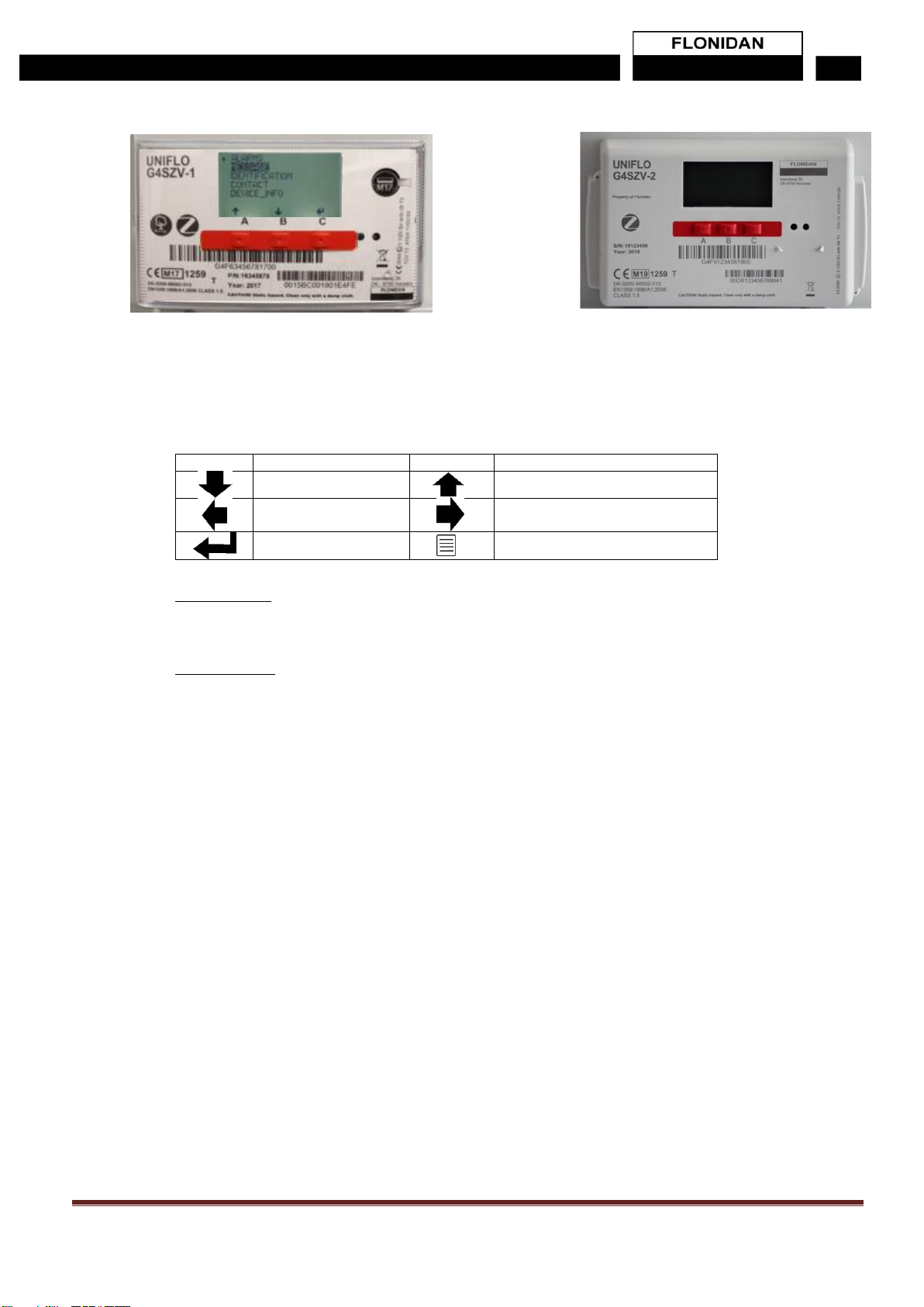
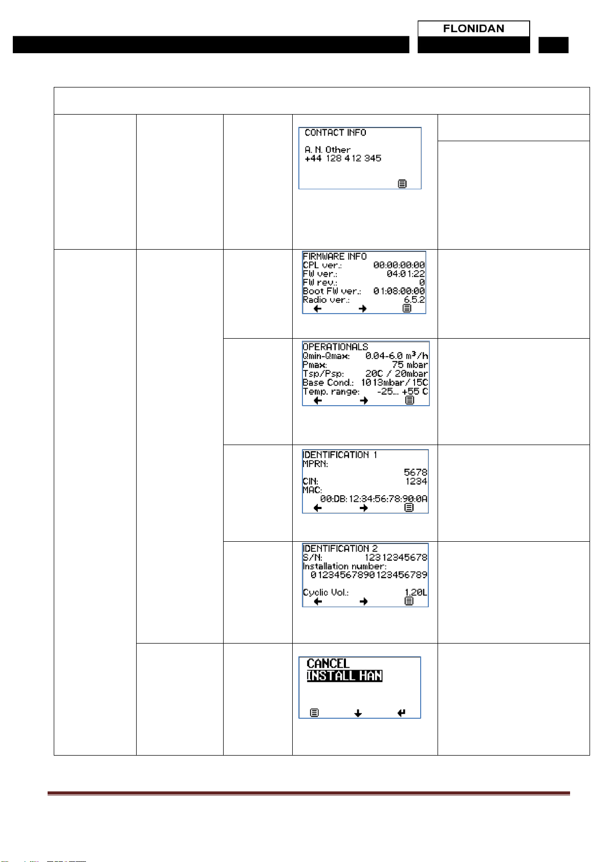
2.7 Model Variants & Identification ........................................................................................10
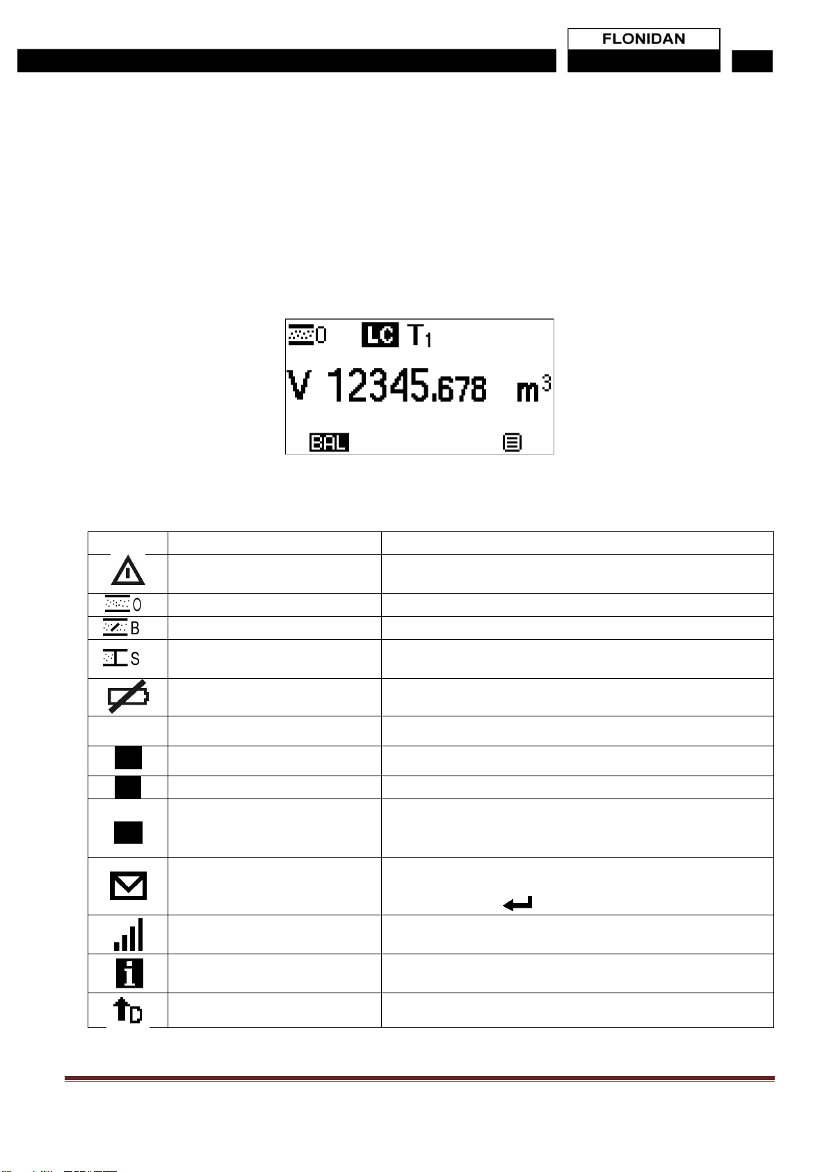
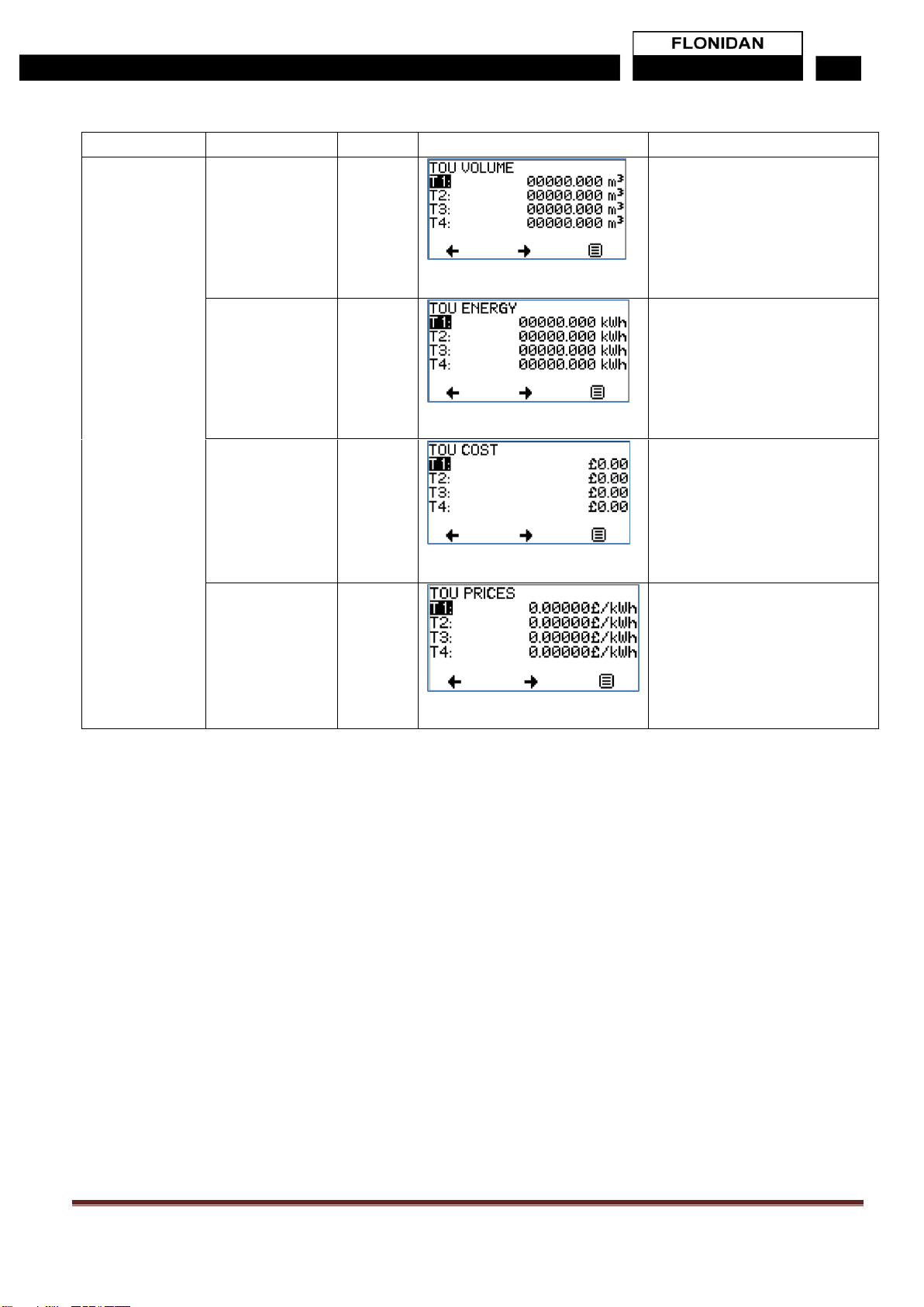
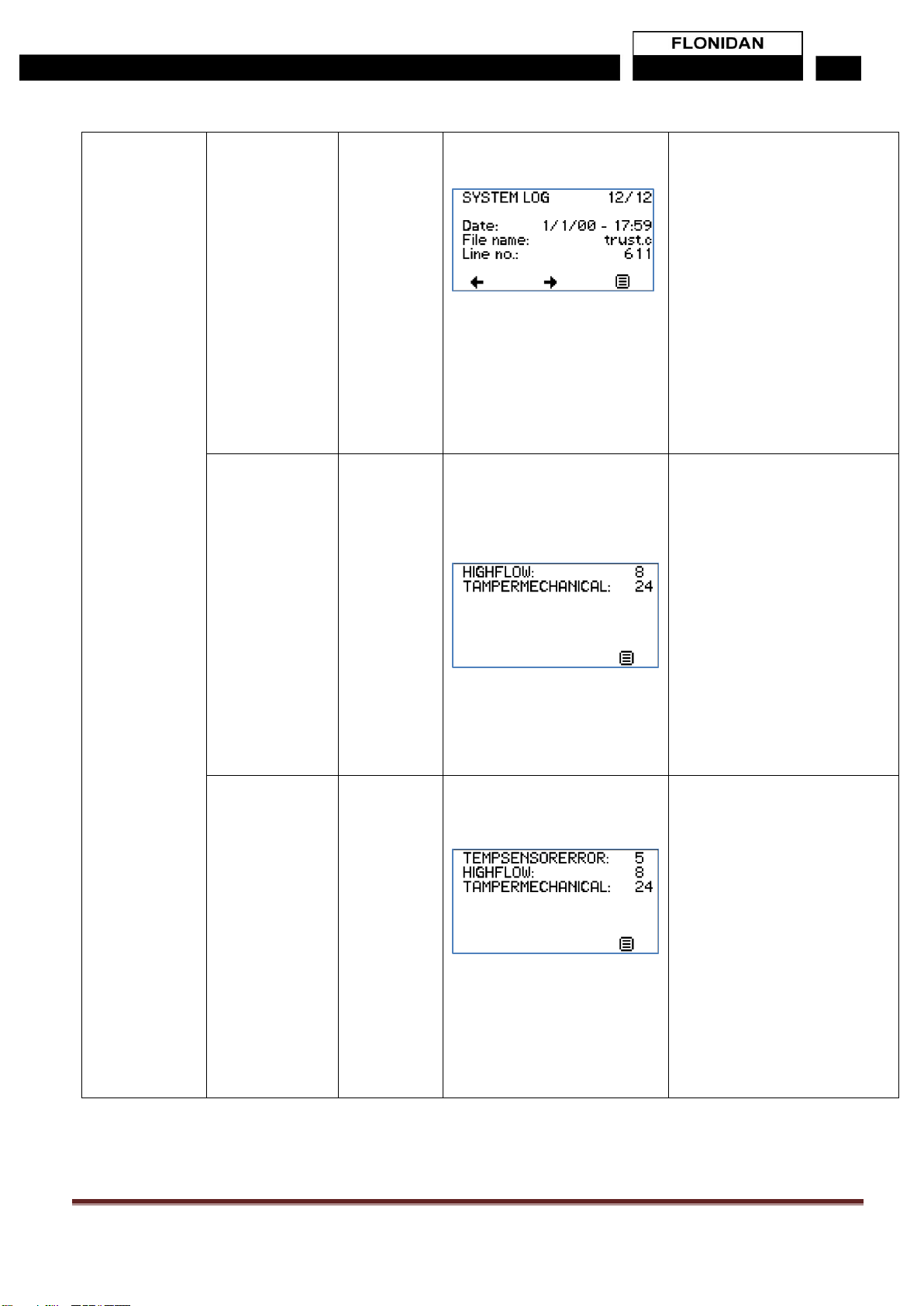
2.8 Liquid Crystal Display ......................................................................................................11
2.8.1 CUSTOMER PIN CODE. ..........................................................................................13
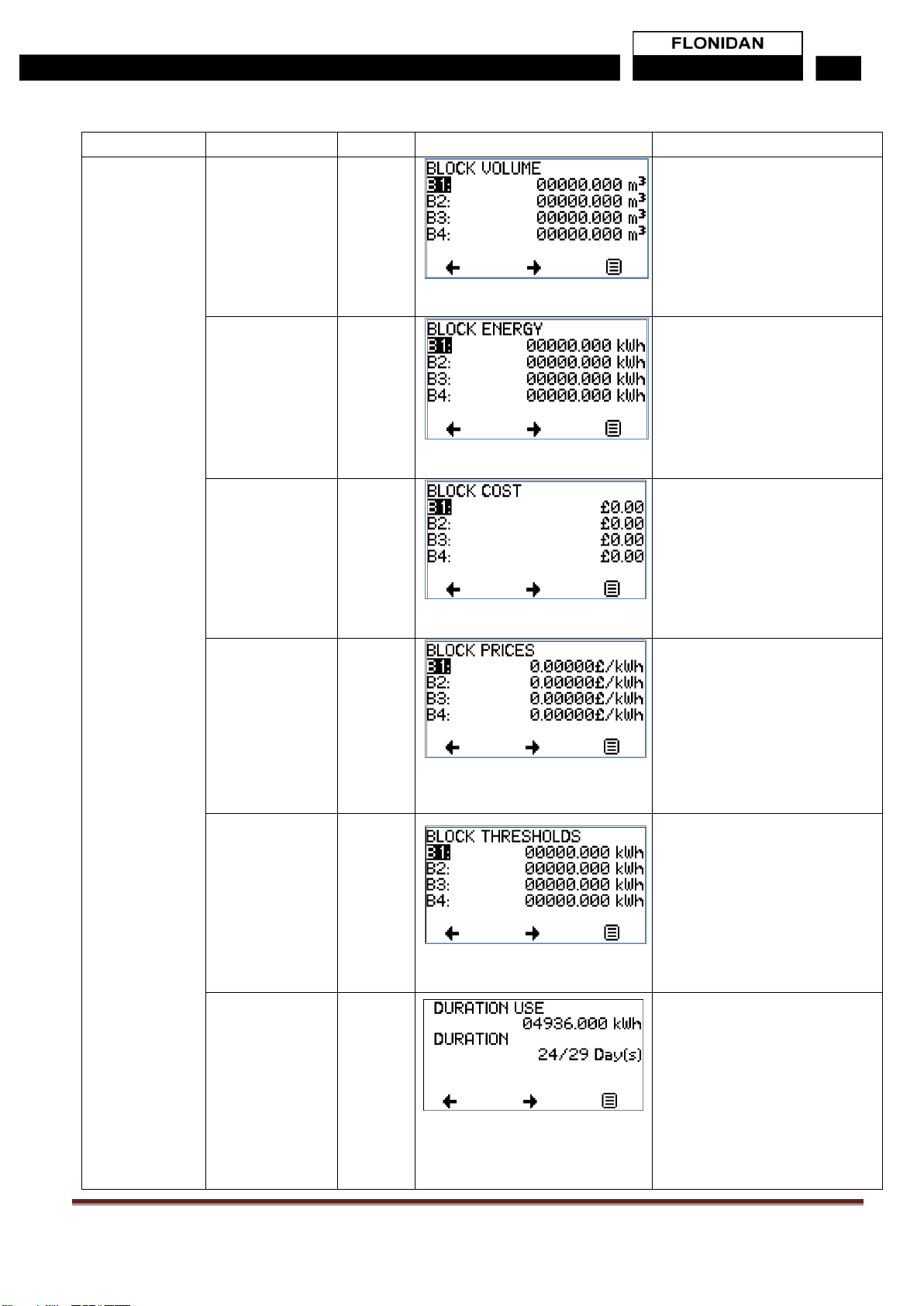
2.8.2 Menu Structure..........................................................................................................14
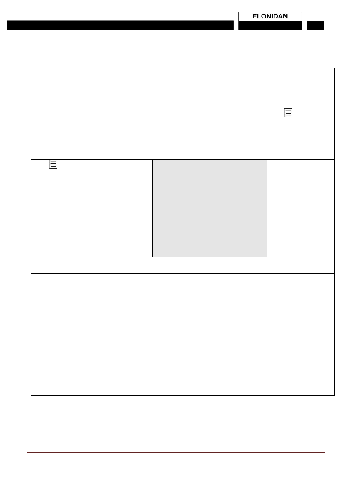
2.8.3 Input methods using Push Buttons............................................................................24
3. Billing and Tariffs..........................................................................................25
3.1 Tariffs...............................................................................................................................25
3.2 Block Tariffs.....................................................................................................................25
4. Mechanical Operation...................................................................................26
4.1 Diaphragm Valve Mechanism..........................................................................................26
4.2 Encoder Index..................................................................................................................26
4.3 Gas Flow Measurement...................................................................................................27
4.4 Error Curve Correction.....................................................................................................27
4.5 Temperature Correction...................................................................................................28
5. Meter Security...............................................................................................29
5.1 Index Cover .....................................................................................................................29
5.2 Metrology Compartment Tamper Detection.....................................................................30
5.3 Magnetic Tamper Detection.............................................................................................30
5.4 Encryption........................................................................................................................30
6. Memory..........................................................................................................30
7. Supply Valve (Electro Valve)........................................................................30
7.1 Supply Disconnect (close valve)......................................................................................31
7.1.1 Supply Disconnection from HES ...............................................................................31
7.1.2 Supply Disconnection during Prepay operation mode...............................................31
7.1.3 Supply disconnection due to an Alarm......................................................................31
7.1.4 Supply Re-connect (open valve) ...............................................................................31
7.1.5 Supply re-connection (Arming) from HES .................................................................31
7.1.6 Supply re-connection (Arming) during Prepay operation mode.................................31
7.1.7 Supply re-connection due to an Alarm being cleared................................................32
7.2 Supply (valve) status........................................................................................................32
7.3 Safe Opening Process.....................................................................................................32
8. Firmware........................................................................................................33
8.1 Firmware Variants............................................................................................................33

G4SZV-1/G4SZV-2 & G4SDZV-2 V1.10 Page 4
8.2 Firmware Upgrade...........................................................................................................34
9. Change of Supplier (CoS).............................................................................34
10. Change of Tenancy (CoT)...........................................................................34
11. Communication Features and Functionality.............................................34
12. Clock............................................................................................................35
13. SMETS2 ALERTS ........................................................................................35
14. FLONIDAN Alarms data logging ................................................................36
14.1 Data logging...................................................................................................................36
14.2 ALERTS and event log ..................................................................................................37
14.3 Battery Low Alarm..........................................................................................................37
14.4 Out of range Alarm.........................................................................................................37
15. Maintenance................................................................................................37
15.1 Battery life Calculation...................................................................................................37
15.2 Battery exchange...........................................................................................................37
15.3 Service...........................................................................................................................38
15.4 Repair............................................................................................................................38
15.5 Returning a Meter..........................................................................................................38
15.6 Meter Disposal...............................................................................................................38
15.7 Cleaning.........................................................................................................................38
15.8 Storage..........................................................................................................................38
16. Technical Specifications at a glance.........................................................39
17. Abbreviations..............................................................................................39

G4SZV-1/G4SZV-2 & G4SDZV-2 V1.10 Page 5
1. Before You Start
The G4S series meter is a high accuracy measuring instrument that must be handled with
care. The meter should always be kept in vertical position, in service and during
transportation.
The device should be fitted only by competent engineers, qualified to the relevant national
legal requirements and following all national and local regulations such as BS 6400
2. Product Description
G4S series meter is a smart diaphragm gas meter, SMETS compliant, with an electronic
index. The meter includes ZigBee radio and an integrated electrically operated valve. The
meter displays the accumulated consumption in m3 or currency, selectable by the menu
system, on an integral LCD.
This G4 (U6) capacity diaphragm gas meter i.e. Qmax = max flow rate = 6 m3/h, is
intended for domestic and small industrial use.
The measuring chamber is a “sliding D” diaphragm type. An optical interface provides the
coupling between the measurement chamber inside the casing and the electronic index.
The optical interface uses a Gray code methodology providing reliability, very precise
accuracy. The meter is also fitted with a device to prevent reverse flow.
The dot matrix display allows for the two lines of data required by SMETS1. In addition,
there’s space for other icons used to assist the end user or installations engineer.
The meter has a HAN interface solution designed for the ZigBee RF interface 2.4MHz or
868 MHz (MKII only) and the SEP 1.X requirements as specified in SMETS
A user-friendly configuration software allows all functions to be accessed by the optical
communications connection located on the front face of the index.
Reading and writing possibilities can be controlled by a customised setup file.
NOTE!, this interface is disabled during normal operation and can only be used for triage
purposes, once the meter is off the wall and disconnected.
The meter can be configured (by the HES) to run in two modes
1 Credit mode: the user will accumulate charges that will be shown on the display.
This will be transferred to the HES and an automatic bill can be generated, on a
monthly or Quarterly period.
2 Prepay mode: the user will purchase “upfront” an amount of prepaid credit that
they will then be able to use. This prepay credit is purchased “online” or in local
shops and is known as a UTRN code (Universal Transaction Reference Number)
after the total prepaid amount is depleted the gas meter will close the gas supply.
Certain measures are implemented to prevent closure at certain times (i.e. when
the shops are closed and it is not possible to purchase a UTRN, these are known
as Friendly credit periods and are decided by the utility alone), in addition special
emergency credit facilities may be offered in certain circumstances.

G4SZV-1/G4SZV-2 & G4SDZV-2 V1.10 Page 6
The meter has an internal valve, electronically controlled, to allow the gas supply to
be disconnected and reconnected as required. The gas supply cannot be
reconnected without the presence of someone at the meter. When the command to
open the valve is received by the meter, a button press is then required at the
meter. If the meter detects passing gas above a predefined rate, indicating a
potential gas leak, it will close the valve. Checks should then be made to ensure
gas appliances are turned off before a second attempt to open the valve is made.

G4SZV-1/G4SZV-2 & G4SDZV-2 V1.10 Page 7
Physical Component Overview
Electronic index
A: G4SZV & G4SZV-1 (MKI)
B: G4SZV-2 & G4SDZV-2 (MKII)
Installation
seals
(side locks)
Optical port
Display
Verification
seal
Press buttons
Battery behind
cover and label
Meter Serial Number
(MSN)
GUID (MAC NUMBER)
Display
Installation
seals
Battery behind
cover

G4SZV-1/G4SZV-2 & G4SDZV-2 V1.10 Page 8
2.1 Dimensions
G4SZV & G4SZV-1 (MKI):
G4SZV-2 & G4SDZV-2 (MKII)
H
W
D
d
c/c
T
M
Mm
mm
mm
mm
mm
mm
kg
G4
262
235
167
73
152
BS 1”
2.5
H
W
D
d
c/c
T
M
Mm
mm
mm
mm
mm
mm
kg
G4
262
235
170
73
152
BS 1”
2.5

G4SZV-1/G4SZV-2 & G4SDZV-2 V1.10 Page 9
2.2 Gas Flow Rates
1) Air, at Qmax.
2) Temperature compensation optional
2.3 Pipe Connection
Pipe connection size : 1” BSP, sealing gasket required
Inlet pipe connection : Left side
Outlet pipe connection : Right side
Direction of flow : Left to right
2.4 Optical Port
NOTE, due to CPA security concerns, this port is turned off at manufacture
and cannot be used in the field.
Optical interface (IEC 62056-21) for specialist maintenance.
2.5 Battery
Type : C cell, Lithium, 3.6V
Lifetime : > 15 years, with normal use
The index and valve are powered by the battery. However, to enable high peak
current supply, a super-capacitor is charged over a long time and discharged
over a short time to operate the motor of the valve.
Note: Only approved battery cells may be used in this product to maintain
ATEX intrinsic safety certification. Please contact the Flonidan for the correct
replacement battery.
Vcyc.
Qmax
Qmin
Pmax
ΔP1)
TC2)
dm3
m3/h
m3/h
bar
mbar
G4
1.2
6
0.04
0.5
1.6
X

G4SZV-1/G4SZV-2 & G4SDZV-2 V1.10 Page 10
2.6 Operating Range
Environmental class
Climate : Outdoor, sheltered, condensing.
Mechanical and Electromagnetic class : M1, E2
ATEX : II 2/2 G Ex ia/ib IIB T3
The meter is designed for use in a hazardous area according to EU Directive
1994/9/2007.
Refer to marking on meter.
Temperature range:
Tamb.: -25...+55°C
Tgas.: -25...+55°C
Gas types:
The gas meter is suitable for gas families 1, 2 and 3 according to EN 437:2003
Max. pressure:
200 mbar gauge
Metering Accuracy
MID Class 1.5
2.7 Model Variants & Identification
The Model name as shown on the index label takes the form –below and example:
G4SZV -2
X is version (eg 1 = SMETS2 MK1 & 2 = SMETS2 MK2)
V: Integrated valve
Z: ZigBee (2.4GHz) or DZ (2.4GHz / 868 MHz)
S: Smart Meter
G4: Meter G-size or G4-6 (covers G4 & G6)
Future variants could include different flow range and different communication
interface type.
The type and version of the PCB located inside the index may be read by an
optical interface, through the front cover. Along with the hardware and firmware
type and versions, you can read the entire configuration of the index. (see section
9.1)
You will also find the unique Meter Serial Number (MSN) of the meter, in the form
“G4F………..” below the display.
There is also the Flonidan internal Part number in the form “P/N 115xxxxxxxx”,
there is full traceability of the internal components of the meter from the either of
these numbers.

G4SZV-1/G4SZV-2 & G4SDZV-2 V1.10 Page 11
2.8 Liquid Crystal Display
Display is readable at angles ± 45° horizontally as well as vertically at temperatures
within the operating range.
Volume read out for the UK is set to the form “xxxxx.yyy” it is not configurable and will
always display leading zeros, as per SECAS rules.
Example: (note leading Zeros may be hidden)
Symbols shown at the top of the display when either the volume or the balance screen is
displayed:
Meaning
Required action
Alarm
Go to the menu, select Alarms + Actual alarms, and you will
see the alarm
Valve open
No action
Valve busy (opening or closing)
Observe if the gas is disabled
Valve shut
When valve is closed, gas is disabled. Contact gas utility, and
press the button when the meter requires it.
Low Battery
Battery must be exchanged within 30 days.
EC
Emergency Credit Available
Use Menu to accept Emergency Credit to avoid disconnection
EC
Emergency Credit in USE
Emergency Credit is being used
LC
Low Credit
Top up, to avoid incurring Debt or being cut off
ND
Non Disconnect
The meter is OUT OF CREDIT, and would have disconnected
but will remain on supply, because of the Non Disconnect
period
Message waiting (from Utility)
Go to menu + Message, and scroll through the incoming
messages.
Acknowledge with
Paired to Communication Hub
All ok. If the symbol is not present, there is no connection to
the HAN
Information waiting (from gas
meter)
Go to menu + Information, and scroll through the incoming
Information. Acknowledge with by pressing button below [i]
Firmware download in progress

G4SZV-1/G4SZV-2 & G4SDZV-2 V1.10 Page 12
Menu driven display, to access all functions on the meter
Navigation symbols are shown at the bottom of the display to indicate the function
of each of the three pushbuttons located directly below:
Symbol
Meaning
Symbol
Meaning
Scroll down
Scroll up
Scroll left
Scroll right
Select, Acknowledge
Main menu
Display test
A display test can be activated through the menu on the User Interface. Chequered
patterns are displayed that covers the entire display to check for failing pixels.
Sleep mode
The display and backlight are turned off after a period of time of inactivity to
conserve battery power. The periods are configurable, with a default setting of both
at 15 seconds. If this display has used its maximum amount of display time
available (configuration setting) the display will not switch on for a period of time
allowing the display time credit to build up again. This function is implemented to
prevent customers draining the battery.

G4SZV-1/G4SZV-2 & G4SDZV-2 V1.10 Page 13
2.8.1 CUSTOMER PIN CODE.
NOTE, If the Customer activates the Customer PIN code, then the main display will change
from A to B, below
A B
If a wrong PIN code has been entered, the following display will occur.
The PIN lock symbol will obscure the Prepay symbols, and any attempt to show the BALANCE
or enter the Menu will require the customer to enter the correct PIN code, in other words the
ONLY information that is readily visible, is the Volume dispensed and the VALVE status, for
safety reasons, all other information is protected by the PIN Code! See section 8.2.8 on how to
enter the code.
The length of time for temporary access after PIN entry is 30 seconds after last interaction.

G4SZV-1/G4SZV-2 & G4SDZV-2 V1.10 Page 14
2.8.2 Menu Structure
The “normal” and default display is the Vc i.e. Total Volume in m3
The display can be switched between Vc (m3) & Meter balance £ using the left hand
button which is marked “A” shown on the display as “BAL” or “VOL”
While in the “normal” display the meter can be switched into the Menu structure below using the Key
Note if no buttons are pressed for approx. 10 seconds, the meter will exit the menu and return to the Normal
display.
Level 1
Level 2
Level 3
Display read out
Comments
Use
Key to enter
Menu
structure
below
In the order
shown from
top to bottom
Typical display for
credit meter
METER
BALANCE
This returns the
display to the normal
volume display
INSTALL
SELECT this to start install process
See installation manual for screens and
process
NOTE This option is
ONLY shown if the
meter has not been
paired and is for the
use of installers only!
WAKE UP
This wakes up the meter and it will check
for any pending messages.
This allows the end
user or engineer to
force an extra wake up
(only once per 30
mins) This option will
disappear for 30 mins
once pressed.
METER BALANCE
INSTALL
WAKE UP
BLOCK USAGE or TIME OF USE
PREPAYMENT (if prepayment is in use)
STATUS
ALERTS
MESSAGES
DEVICE INFO
USER SETTINGS
CONTACT

G4SZV-1/G4SZV-2 & G4SDZV-2 V1.10 Page 15
Level 1
Level 2
Level 3
Display read out
Comments
TIME OF USE
Only displayed
if Time of use
is being used.
TOU VOLUME
Total volume m3
metered
Switch between the 4 screens
using ← →
Volume per Time period in m3
in the form xxxxx.yyy
TOU ENERGY
Total Energy
kWh metered
Switch between the 4 screens
using ← →
kWh per Time period in the
form “xxxxx.yyy
TOU COST
Total money
£metered for
each Tariff
Switch between the 4 screens
using ← →
Cost per Time period in the
form £ “x.yy”
TOU PRICES
in £/kWh for
each tariff
Switch between the 4 screens
using ← →
Price per Time period £/kWh in
the form “x.yyyyy”

G4SZV-1/G4SZV-2 & G4SDZV-2 V1.10 Page 16
Level 1
Level 2
Level 3
Display read out
Comments
BLOCK
Only displayed
if Block Pricing
is being used.
Block VOLUME
Total volume m3
metered
Switch between the 6 screens
using ← →
Volume for each Block period
m3in the form xxxxx.yyy
Block ENERGY
Total ENERGY
kWh metered
Switch between the 6 screens
using ← →
kWh for each Block period in
the form “xxxxxxx.yyy
Block COST
Total money £
metered for
each tariff
Switch between the 6 screens
using ← →
Value £ for each Block period
in the form “x.yy”
Block PRICES
In £/kWh for
each Tariff
Switch between the 6 screens
using ← →
Price for each Block period
£/kWh in the form “x.yyyyy
Block
Thresholds
Switch between the 6 screens
using ← →
Block Threshold for each
Block period in the form
“xxxxx.yyy kWh
NOTE B1 will always be zero a
the starting point.
Block USED
Switch between the 6 screens
using ← →
This refers to the current total
block duration USE:
kWh, this is the total that has
been used in this block tariff
(billing) period ie
(B1+B2+B3+B4)
Duration: is days that this has
taken / Total block days (billing
period)
(blank if no volume used yet)

G4SZV-1/G4SZV-2 & G4SDZV-2 V1.10 Page 17
Level 1
Level 2
Level 3
Display read out
Comments
PREPAYMENT
Only displayed
if Prepayment
mode is active.
TOPUP LOGS
For each of the last 5 top ups
the display will show The Date,
amount, Ref and Code
NEW
PAYMENT
This will allow a UTRN to be
inputted (see section 2.8.2)
DEBT
Switch between the 4 screens
using ← →
Time based Debt 1
Switch between the 4 screens
using ← →
Time based Debt 2
Switch between the 4 screens
using ← →
Payment Based Debt
In %
Switch between the 4 screens
using ← →
Accumulated Debt £
Debt to clear £
EMERG.
CREDIT
NOTE!
only
shown
in
prepay
mode
Status: Not Available/
Available /in use/Exhausted
Limit: This is the limit set by
the Head End system
Remaining: This is the
emergency credit remaining

G4SZV-1/G4SZV-2 & G4SDZV-2 V1.10 Page 18
Level 1
Level 2
Level 3
Display read out
Comments
STATUS
PAYMENT
MODE
Active Credit Mode /
Prepayment Mode
Shows either Credit or
Prepayment mode as active
CURRENT
STATUS
CURRENT
STATUS
Switch between the 3 screens
using ← →
Shows:
Current Tariff being applied
Current Standing Charge
Current price
Current valve status
ACTUAL
VALUES
Switch between the 3 screens
using ← →
Shows:
Current date and time
Uptime since the last reset
Current temperature
Bat use in uA/day
Bat left, in days
FLOW
VALUES
Switch between the 3 screens
using ← →
Shows:
Current flow rate litres/hour
Max flowrate TODAY!
ALERTS
EVENT LOG
Shows: Event X/Y
Where X is the position in the
event log and y shows how
many entries there are. (max
100
The Alert code is from the
GBCS alert list. GBCS table
16.2
Other info, if the event has a
2nd byte
SECURITY
LOG
NOTE
access to
this log is
ONLY
available if
the Secure
perimeter is
broken, ie
the side
locks are
removed,
and the front
cover is
removed (as
per
SMETS2
4.4.5
requirement)
Shows: Event X/Y
Where X is the position in the
security log and y shows how
many entries there are. (max
100
The Alert code is from the
GBCS alert list. GBCS table
16.2
Other info, if the event has a
2nd byte

G4SZV-1/G4SZV-2 & G4SDZV-2 V1.10 Page 19
SYSTEM LOG
NOTE
access to
this log is
ONLY
available if
the Secure
perimeter is
broken, ie
the side
locks are
removed
and the front
cover is
removed
This is an
internal
Flonidan
log
Shows: Event X/Y
Where X is the position in the
security log and y shows how
many entries there are. (max
100
Date: the date and time that
this occurred
File Name, internal reference
Line no: The line in the code
NOTE! This information is only
used by Flonidan for triage
work.
Actual Alarms
NOTE
access to
this log is
ONLY
available if
the Secure
perimeter is
broken, ie
the side
locks are
removed
and the front
cover is
removed
This is an
internal
Flonidan
log
Shows the list of currently
active alarms ie that have not
yet ceased or have not yet
been cleared (and the number
of activations, since it was last
cleared)
Note all alarms are “cleared” at
midnight to ensure if they still
exist they will re-occur
His Alarms
NOTE
access to
this log is
ONLY
available if
the Secure
perimeter is
broken, ie
the side
locks are
removed
and the front
cover is
removed
This is an
internal
Flonidan
log
Shows the list of alarms that
have occurred in the past but
have ceased (or been cleared)
Note all alarms are “cleared” at
midnight to ensure if they still
exist they will re-occur, but not
the historical alarms list.

G4SZV-1/G4SZV-2 & G4SDZV-2 V1.10 Page 20
Level 1
Level 2
Level 3
Display read out
Comments
MESSAGES
Up to 116 char, auto
scrolling.
Up to 5 Messages that have
been sent from the Utility
Switch between each
message using ← →
DEVICE INFO.
METER INFO
FIRMWARE
INFO
Switch between the 4
screens using ← →
CPL FW version
Index FW version
Index FW Revision
Boot FW version
Radio FW version
Operational
witch between the 3 screens
using ← →
Min and Max flow rates
Max Pressure
Temperature & Pressure at
normal operational conditions
Base conditions
Allowable Temp range
Identification
1
Switch between the 3
screens using ← →
MPRN number
Customer Identification
Number (CIN)
Mac code / GUID
Identification
2
witch between the 3 screens
using ← →
Flonidan Serial Number
Installation Number (MSN)
Cyclic Vol.: 1.2L
HAN STATUS
(1)
These options are only shown
if the Meter has not yet been
installed and paired.
Cancel allows you to return to
the main DEVICE INFO menu
Install HAN will start the install
process. (see installation
manual)
This manual suits for next models
3
Table of contents
Other Flonidan Measuring Instrument manuals
Popular Measuring Instrument manuals by other brands

Extech Instruments
Extech Instruments 407412 user manual

NeurOptics
NeurOptics NPi-200 Instructions for use

Agilent Technologies
Agilent Technologies B1500A Training manual

Sensory Analytics
Sensory Analytics Specmetrix SA Installation & operation manual

Hydreka
Hydreka 801 Operation manual

Hioki
Hioki 9605 instruction manual