Trend Micro EdgelIPS Pro-2096 User manual

Opening and Inspecting the Package1
1
Examining the EdgeIPS Pro-20961
2
Console Cable
(USB-Type-C)
DocumentsPower Cord x 2
EdgeIPS Pro-2096 Front Panel
EdgeIPS Pro-2096 Appliance
SECUREDBY
EdgeIPS Pro-1048
Power Cord Strain Relief Kit
EdgeIPS Pro-2096 is a Transparent Security
Appliance. Support up to 24 pair IPS segments,
Users can efficiently adapt the rack mount-sized
EdgeIPS Pro-2096 into a flexible solution for the
challenges of Ethernet communications.
EdgeIPS
Quick Setup Guide
TM
Pro-2096
-1 -
x10 x2
M4
M5
x5
Rail Mount Kit
(EdgeIPS Pro-2096)
SECURED BY
SLOT1 SLOT3 SLOT2 SLOT4
1-2 3-4 5-6 7-8 9-10 11-12BP
1
23
4
PORT 5
67
89
10 11
12
13-14 15-16 17-18 19-20 21-22 23-24
13
14 15
16 17
18 19
20 21
22 23
24
1-2 3-4 5-6 7-8 9-10 11-12BP
1
23
4
PORT 5
67
89
10 11
12
13-14 15-16 17-18 19-20 21-22 23-24
13
14 15
16 17
18 19
20 21
22 23
24
1-2 3-4 5-6 7-8 9-10 11-12BP
1
23
4
PORT 5
67
89
10 11
12
13-14 15-16 17-18 19-20 21-22 23-24
13
14 15
16 17
18 19
20 21
22 23
24
1-2 3-4 5-6 7-8 9-10 11-12BP
1
23
4
PORT 5
67
89
10 11
12
13-14 15-16 17-18 19-20 21-22 23-24
13
14 15
16 17
18 19
20 21
22 23
24
PWR1
PWR2
STAT E
MGMT
HA
USB
FAIL
RESET
MGMTHA
MROIOI
SECURED BY
SLOT1 SLOT3 SLOT2 SLOT4
1-2 3-4 5-6 7-8 9-10 11-12BP
1
23
4
PORT 5
67
89
10 11
12
13-14 15-16 17-18 19-20 21-22 23-24
13
14 15
16 17
18 19
20 21
22 23
24
1-2 3-4 5-6 7-8 9-10 11-12BP
1
23
4
PORT 5
67
89
10 11
12
13-14 15-16 17-18 19-20 21-22 23-24
13
14 15
16 17
18 19
20 21
22 23
24
1-2 3-4 5-6 7-8 9-10 11-12BP
1
23
4
PORT 5
67
89
10 11
12
13-14 15-16 17-18 19-20 21-22 23-24
13
14 15
16 17
18 19
20 21
22 23
24
1-2 3-4 5-6 7-8 9-10 11-12BP
1
23
4
PORT 5
67
89
10 11
12
13-14 15-16 17-18 19-20 21-22 23-24
13
14 15
16 17
18 19
20 21
22 23
24
PWR1
PWR2
STATE
MGMT
HA
USB
FAIL
RESET
MGMTHA
MROIOI
SECUREDBY

-2 -
Requirement Details
Connect to the Management Port for accessing web console
management.
Default web console access information:
https://192.168.127.254
Ethernet Cables
Default IP Address of
Web Console
The computer must have one of the following browsers installed:
- Microsoft Edge (version 15 or above)
- Firefox (version 53 or above)
- Safari (version 10.1 or above)
- Google Chrome (version 63 or above)
Laptop with Ethernet
Port (RJ-45 Type)
User Name: admin
Password: txone
Deployment Scenario and System Operation Mode
4
Deployment Checklist1
3
1
Control Center Network
Backbone Network
MES Database HistorianOPC Client
MESHMI PLC
Control System Network
MESHMI PLCMESHMI PLC
Production Line - 1 Production Line - 12 Production Line - 48
Field-bus
EdgeIPS Pro-2096
Control System Network
Field-bus
Control System Network
Field-bus
SECUREDBY
-1 -

-3 -
LED Indicators1
5
The function of each LED is described in the table below
Green
Power 1 is off
Off
Power 1 is on, and device is functioning normally
PWR1
Green
Power 2 is off
Off
Power 2 is on, and device is functioning normally
PWR2
Green
System fail, fail LED will also be turned on
Off
System is running normal
STATE
Green
OT Defense console sync is disabled
Off
OT Defense Console Sync (ODC) is enabled and ODC is connected
MGMT
Green
High-Availability feature is tunred off
Off
High-Availability feature is tunred on
HA
Green
Hardware or system fault
Off
LED will be turned on when USB is plugged in
USB
Red
System is running normal
Off
System fail which includes hardware and software
Fail
Reset type Description
Press and hold the reset button for 2 to 10 seconds. The STATE LED
will begin to blink on a 1-second pattern, which means the system is
rebooting.
Press and hold the reset button for more than 10 seconds. The STATE
LED will begin to blink every half-second, which means the system is
resetting itself to factory defaults.
Reboot System
Restore Factory
Default Settings
Reset to factory default setting1
6
The reset button for the EdgeIPS Pro-2096 is located on the front panel.
SECURED BY SLOT1 SLOT3 SLOT2 SLOT4
1-2 3-4 5-6 7-8 9-10 11-12BP
1
23
4
PORT 5
67
89
10 11
12
13-14 15-16 17-18 19-20 21-22 23-24
13
14 15
16 17
18 19
20 21
22 23
24
1-2 3-4 5-6 7-8 9-10 11-12BP
1
23
4
PORT 5
67
89
10 11
12
13-14 15-16 17-18 19-20 21-22 23-24
13
14 15
16 17
18 19
20 21
22 23
24
1-2 3-4 5-6 7-8 9-10 11-12BP
1
23
4
PORT 5
67
89
10 11
12
13-14 15-16 17-18 19-20 21-22 23-24
13
14 15
16 17
18 19
20 21
22 23
24
1-2 3-4 5-6 7-8 9-10 11-12BP
1
23
4
PORT 5
67
89
10 11
12
13-14 15-16 17-18 19-20 21-22 23-24
13
14 15
16 17
18 19
20 21
22 23
24
PWR1
PWR2
STATE
MGMT
HA
USB
FAIL
RESET
MGMTHA
MROIOI
SECURED BY SLOT1 SLOT3
1-2 3-4 5-6 7-8 9-10 11-12BP
1
23
4
PORT 5
67
89
10 11
12
13-14 15-16 17-18 19-20 21-22 23-24
13
14 15
16 17
18 19
20 21
22 23
24
BP
PORT
1-2 3-4 5-6 7-8 9-10 11-12BP
1
23
4
PORT 5
67
89
10 11
12
13-14 15-16 17-18 19-20 21-22 23-24
13
14 15
16 17
18 19
20 21
22 23
24
BP
PORT
PWR1
PWR2
STAT E
MGMT
HA
USB
FAIL
RESET
MGMTHA
MROIOI
-2 -

-4 -
Installing the EdgeIPS Pro1
7
The aluminum Rail attachment plate should already be fixed to the back panel of the EdgeIPS
Pro-2096 when you take it out of the box. If you need to reattach the Rail attachment plate to
the EdgeIPS Pro-2096, make sure the stiff metal spring is oriented towards the top, as shown
in the following pictures.
Pull chassis (inner)
member out
Press the trigger
down to release
Step1.
Step2.
Step3.
T
T
A
A
A
Standoff
T
1.5
1.5
M4
2.0
A
A
A
-3 -

-5 -
Step4.
Step5.
Step6.
Release safety lock
before mounting
Push the safety lock
forward to secure
Retainer is in fully open position
Press trigger down to release the slides from locking
-4 -

-6 -
Wiring the Redundant Power Inputs1
7
The Trend Micro EdgeIPS Pro has two sets of power inputs – power input1 and power input2.
The top and side views of the terminal block connector are shown below.
Step1.
Prepaing the power code and wire locks.
Step2.
Insert a positive / negative AC wire power code respectively.
Step3.
When the wire is properly seated, the wire lock will be forced shut around it. Check whether
the wire is properly fixed.
Wiring the Redundant Power Inputs1
8
Connecting the Power1
9
Connect the 100 to 240 AC power cord to the power socker, which is connected to the EdgeIPS
Pro device. If the power is supplied properly, the “Power” LED will glow steadily. The power
input location and pin definition are shown in the following diagram.
Grounding the Unit1
10
Grounding and wire routing help limit the effects of noise due to electromagnetic interference
(EMI). Run the ground connection from the terminal block connector to the grounding surface
prior to connecting the power. Please note that this product is intended to be mounted on a
well-grounded mounting surface, such as a metal panel. The minimum cross-sectional area of
the conductor must be equal to the input wiring cable’s width/circumference.
Step1. Step2.
-5 -

-7 -
Wiring the Redundant Power Inputs1
7Software Configuration1
11
Before connecting the PC/Laptop to EdgeIPS Pro-2096, the PC's IP address should be set to
192.168.127.100. After that, connect the PC and EdgeIPS Pro-2096 using an Ethernet cable.
Open a web browser on your PC and type “https://192.168.127.254” into the address bar. A
pop-up window will open to ask for user name and password. Please type the default
username, “admin”, and password, “txone”.
Now, the main screen will pop up so you can configure EdgeIPS Pro.
-6 -

-8 -
Setting the Management IP Address1
12
1. Go to [Network] > [Device Settings]
Connecting to the Network1
13
Task Action
Configure Management IP Address of the EdgeIPS ProDevice IP Address
Configure Netmask of the EdgeIPS ProNetmask
2. In the [Network Setting] plane, configure management IP address for EdgeIPS Pro
Confiture GatewayAddress of the EdgeIPS ProGateway
Configure DNS setting of the EdgeIPS ProDNS
Configure Network VLAN-ID of the deviceNetwork VLAN-ID
Use the management port to access the EdgeIPS Pro Web console from another
computer on your network.
1. Connect one end of a Category 5e Ethernet cable to the MGMT port located on
the front panel.
2. Connect the other end of the cable to an Ethernet port connected to your
network.
-7 -

-9 -
Checking the LED to Confirm Status1
14
The LED on each Ethernet port shows the deployment status.
No Light The EdgeIPS Pro appliance cannot communicate with a network.
MGMT/MR
Left LED GE LINK/ACT (off = no link, on = activity)
Right LED 10 Gbps LINK/ACT (on = 10 Gbps link)
Hardware Bypass LED Indicator1
15
1
15
The Bypass LED on each IPS Pair status.
1-2 3-4 5-6 7-8 9-10 11-12BP
1
23
4
PORT 5
67
89
10 11
12
Bypass LED indication Status
No Light
Port Pair hardware bypass enabledTurn on RED
Port Pair hardware bypass disabled
Right LED 1 Gbps LINK/ACT (on = 1 Gbps link)
Port Pair hardware bypass normalTurn on Green
No Light The EdgeIPS Pro appliance cannot communicate with a network.
HA
Left LED GE LINK/ACT (off = no link, on = activity)
Right LED 100 Mbps LINK/ACT (on = 100 Mbps link)
10 Mbps LINK/ACT (off = 10 Mbps link)
No Light The EdgeIPS Pro appliance cannot communicate with a network.
RJ45
Left LED GE LINK/ACT (off = no link, on = activity)
Right LED 10/100 Mbps LINK/ACT (off = 10 Mbps link, on = 100 Mbps link)
Right LED 1 Gbps LINK/ACT (on = 1 Gbps link)
Right No Light 10/100 Mbps LINK/ACT (off = 10/100 Mbps link)
Right No Light
-8 -

-10 -
© 2021 Trend Micro Incorporated. All Rights Reserved. Trend Micro and the t-ball logo are trademarks or registered trademarks
of Trend Micro Incorporated. All other company and/or product names may be trademarks or registered trademarks of their
owners. Information contained in this document is subject to change without notice.
Contact Information1
Website
https://www.trendmicro.com
List of worldwide offices and phone numbers
https://www.trendmicro.com/us/about-us/contact/index.html
Technical support page
https://success.trendmicro.com/
EULA
https://www.trendmicro.com/en_us/about/legal.html
EdgeIPS Pro Datasheet/Application Note Landing Page
RESET
SLOT1 SLOT2
PWR1
PWR2
STATE
MGMT
HA
USB
FAIL 1-2 3-4 5-6 7-8 9-10 11-12BP
1
23
4
PORT 5
67
89
10 11
12
13-14 15-16 17-18 19-20 21-22 23-24
13
14 15
16 17
18 19
20 21
22 23
24
1-2 3-4 5-6 7-8 9-10 11-12BP
1
23
4
PORT 5
67
89
10 11
12
13-14 15-16 17-18 19-20 21-22 23-24
13
14 15
16 17
18 19
20 21
22 23
24
SECUREDBY
MGMTHA
MROIOI
EdgeIPS Pro-1048
USB Type-C
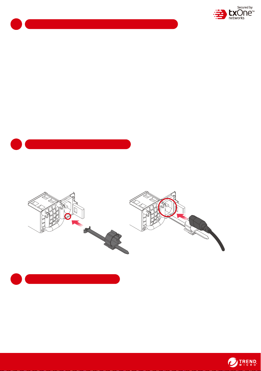
Appendix: Connecting to the Console Port
The EdgeIPS Pro-2096 console port is a USB Type-C Port located on the front panel of the
case. It is designed for connection to serial console terminals for viewing messages during
the boot sequence or for debugging system boot issues. To connect the console cable,
remove the protective cover on the port.
Serial Console Port, Cable & Pinouts
The initial configuration for the EdgeIPS Pro-2096 using the command line interface (CLI) on a
serial terminal client will use the following default settings:
• Baud Rate: 115200 bps
• Character Size: 8 bits
• Parity: None
• Stop Bits: 1
• Flow Control: None
SECURED BY SLOT1 SLOT3 SLOT2 SLOT4
1-2 3-4 5-6 7-8 9-10 11-12BP
1
23
4
PORT 5
67
89
10 11
12
13-14 15-16 17-18 19-20 21-22 23-24
13
14 15
16 17
18 19
20 21
22 23
24
1-2 3-4 5-6 7-8 9-10 11-12BP
1
23
4
PORT 5
67
89
10 11
12
13-14 15-16 17-18 19-20 21-22 23-24
13
14 15
16 17
18 19
20 21
22 23
24
1-2 3-4 5-6 7-8 9-10 11-12BP
1
23
4
PORT 5
67
89
10 11
12
13-14 15-16 17-18 19-20 21-22 23-24
13
14 15
16 17
18 19
20 21
22 23
24
1-2 3-4 5-6 7-8 9-10 11-12BP
1
23
4
PORT 5
67
89
10 11
12
13-14 15-16 17-18 19-20 21-22 23-24
13
14 15
16 17
18 19
20 21
22 23
24
PWR1
PWR2
STATE
MGMT
HA
USB
FAIL
RESET
MGMTHA
MROIOI
SECURED BY SLOT1 SLOT3
1-2 3-4 5-6 7-8 9-10 11-12BP
1
23
4
PORT 5
67
89
10 11
12
13-14 15-16 17-18 19-20 21-22 23-24
13
14 15
16 17
18 19
20 21
22 23
24
BP
PORT
1-2 3-4 5-6 7-8 9-10 11-12BP
1
23
4
PORT 5
67
89
10 11
12
13-14 15-16 17-18 19-20 21-22 23-24
13
14 15
16 17
18 19
20 21
22 23
24
BP
PORT
PWR1
PWR2
STAT E
MGMT
HA
USB
FAIL
RESET
MGMTHA
MROIOI
-9 -
This manual suits for next models
1
Table of contents
Other Trend Micro Measuring Instrument manuals